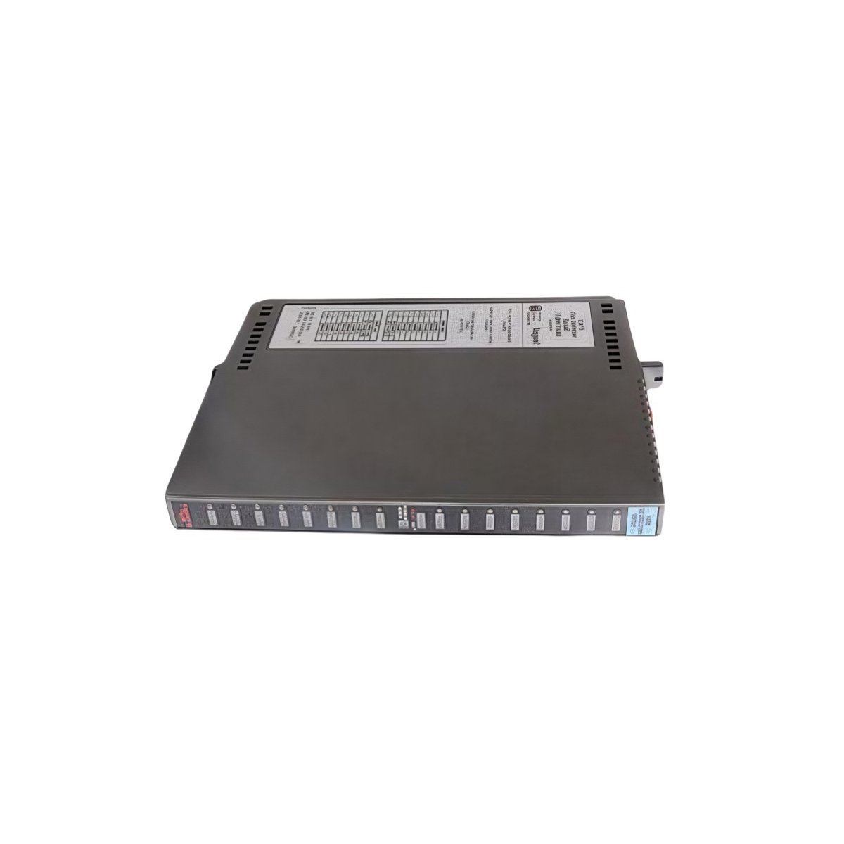
Centralized Intelligence for Universal Relay Systems
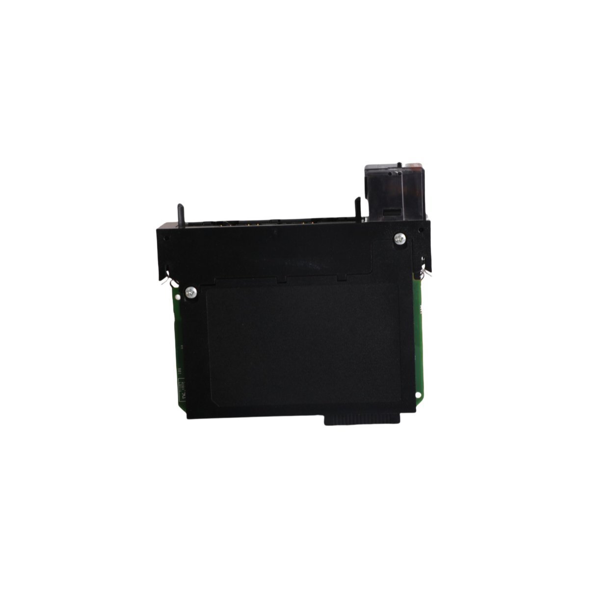
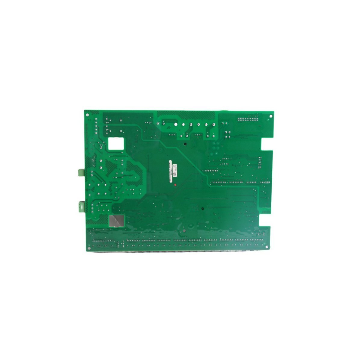
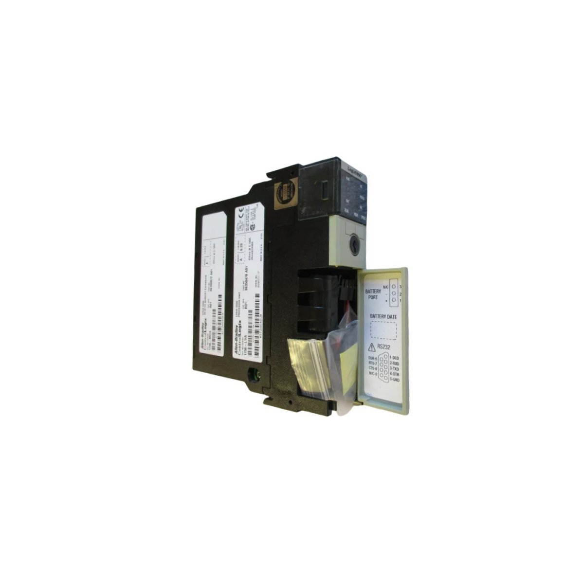
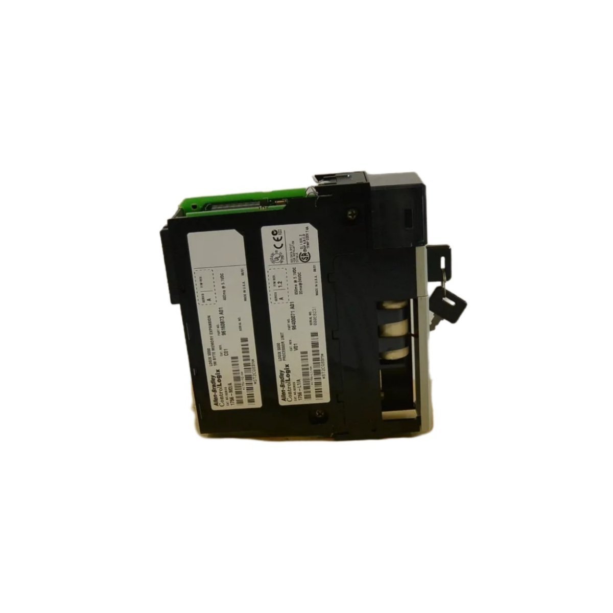
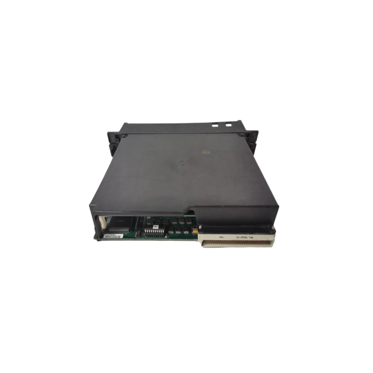
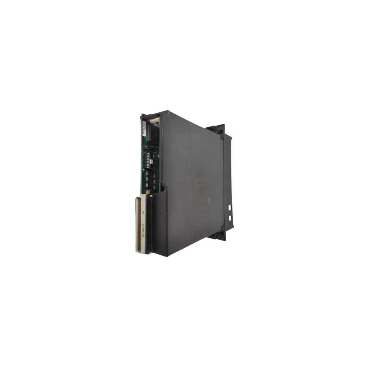
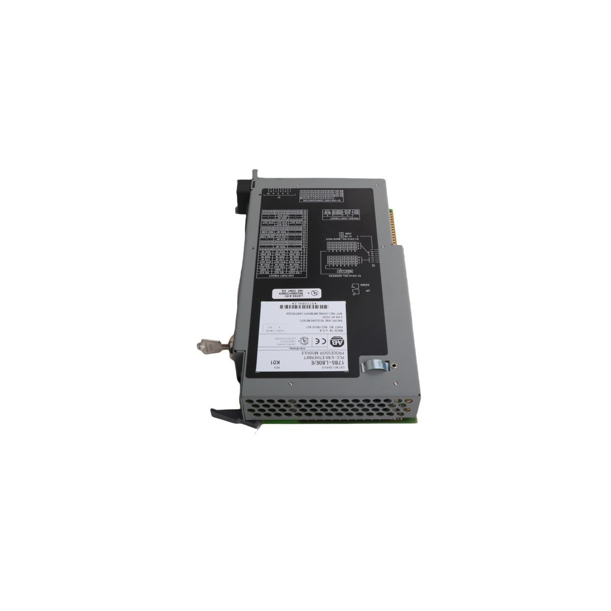
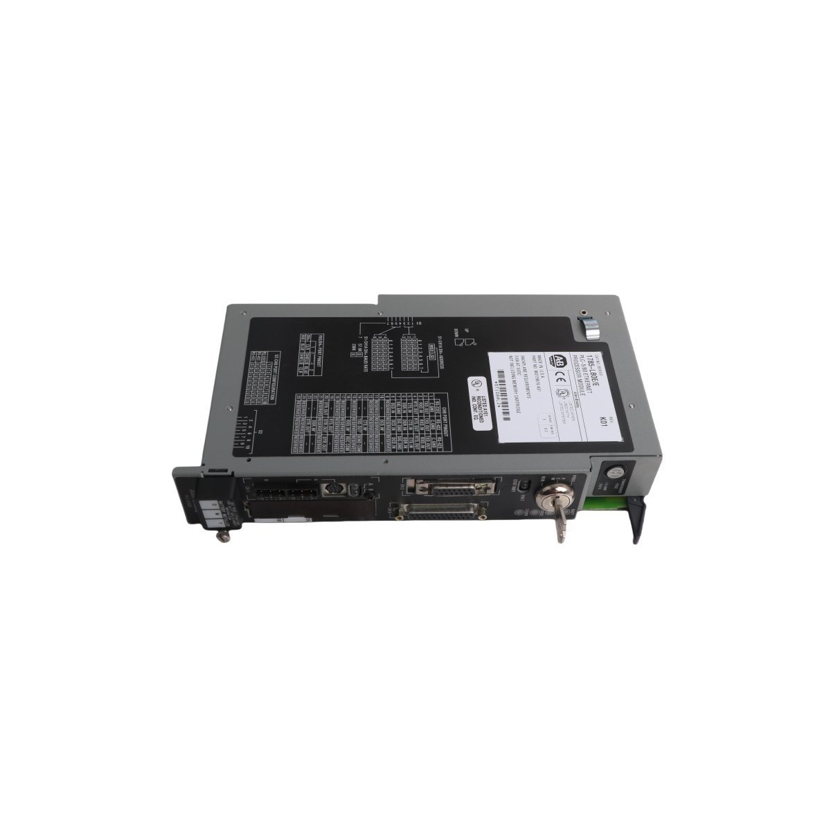
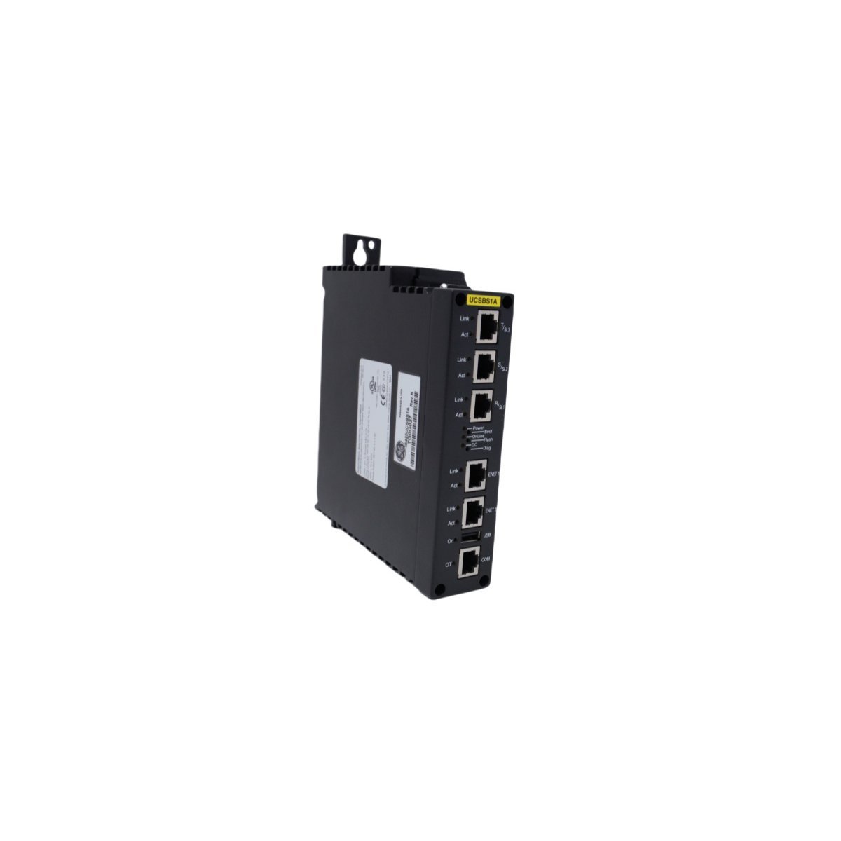
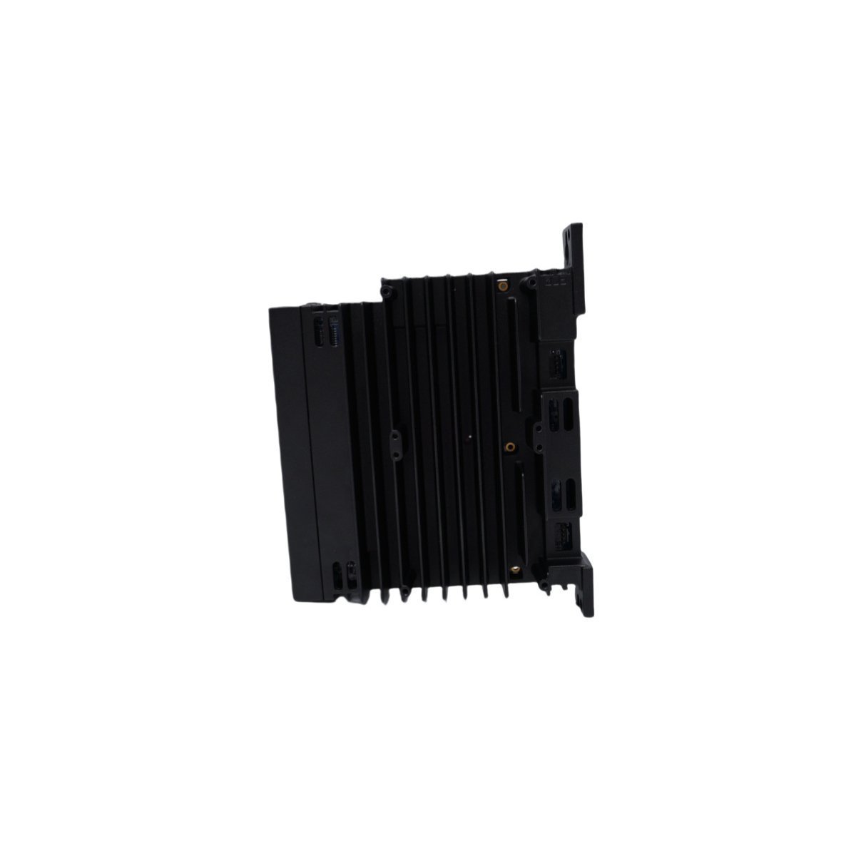
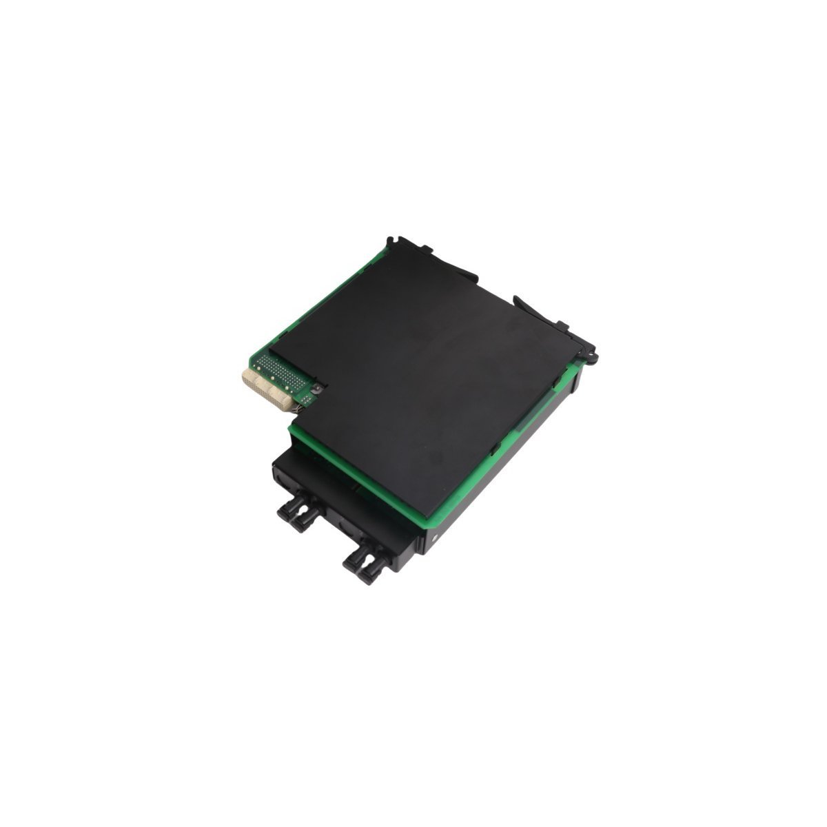
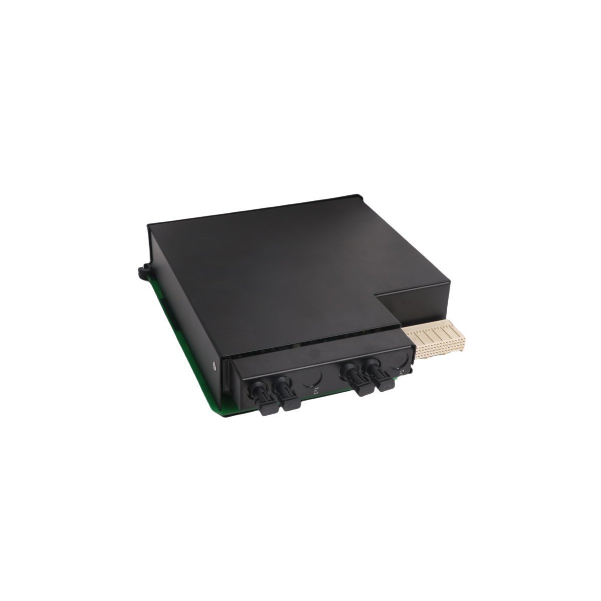
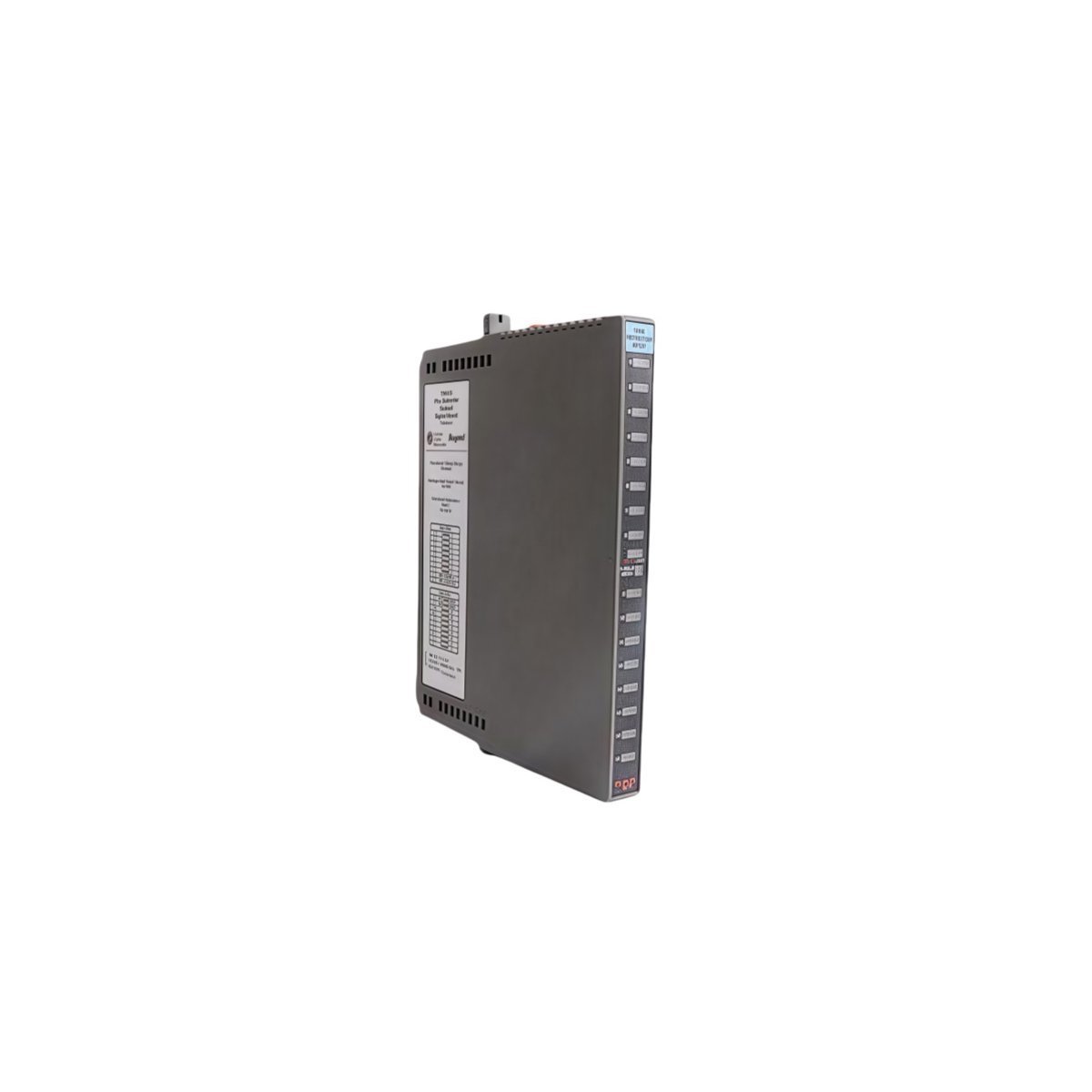
The GE UR7IH operates as the primary processing heart within the Multilin Universal Relay (UR) ecosystem. This module functions as the central intelligence unit, executing the sophisticated logic required for the protection, control, and monitoring of high-voltage power assets. By integrating high-speed CPU technology, the UR7IH processes complex analog and digital signals from across the electrical grid to make critical, sub-cycle protection decisions. Consequently, this control module acts as the indispensable hub for maintaining grid stability and safeguarding expensive infrastructure, such as large-scale transformers and generators.
Innovative Protection Logic and Data Capture
Regarding its technical capabilities, the UR7IH incorporates advanced computational power that supports a wide array of protection elements, including distance, differential, and directional power functions. The module utilizes a high-performance hardware platform to facilitate real-time waveform capture and comprehensive event recording. Furthermore, this data logging capability allows engineers to perform exhaustive post-fault analysis to identify the root causes of system disturbances. Because the unit provides significant processing overhead, it easily handles modern networking protocols like IEC 61850 and IEEE 1588 time synchronization, ensuring that the relay remains fully compatible with digitized substation environments.
Modular Architecture and Lifecycle Efficiency
In addition to its raw processing speed, the UR7IH offers a modular, plug-and-play interface that drastically simplifies system maintenance and hardware transitions. The module features an integrated Ethernet router communication service, which enables seamless data exchange with wider SCADA and DCS networks. Although GE officially moved the UR7IH to a discontinued status on December 31, 2018, it continues to be a vital component for sustaining legacy power systems. Moreover, the standardized footprint of the UR series allows technicians to replace the control module specifically without discarding the entire relay chassis. This design philosophy ensures cost-efficient lifecycle management and reduces electronic waste during system repairs.
Technical Specifications
- Brand: General Electric (GE)
- Model Number: UR7IH
- Product Range: Multilin UR (Universal Relay) Series
- Module Type: UR Control / Processor Module
- Processing Power: High-speed CPU for sub-cycle protection
- System Category: PLC / Protection and Control
- Communication: Ethernet Router / SCADA / IEC 61850
- Weight: 0.84 kg
- Dimensions: 6.0 cm x 19.5 cm x 17.2 cm
- Origin: USA
Strategic Maintenance and Industrial Reliability
Utilities and industrial plants frequently deploy the UR7IH to centralize their protection logic and enhance overall system security. Since the module supports predictive maintenance through detailed trend analysis and diagnostic logging, it empowers operators to mitigate technical risks before they escalate into catastrophic equipment failures. Furthermore, the active monitoring capabilities of the CPU ensure that all protection interlocks remain ready for immediate deployment. By utilizing this authentic GE Multilin component, facilities can extend the operational life of their existing power infrastructure while maintaining the high levels of accuracy required for modern energy distribution.