Sale!
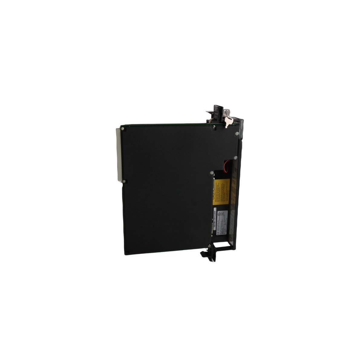
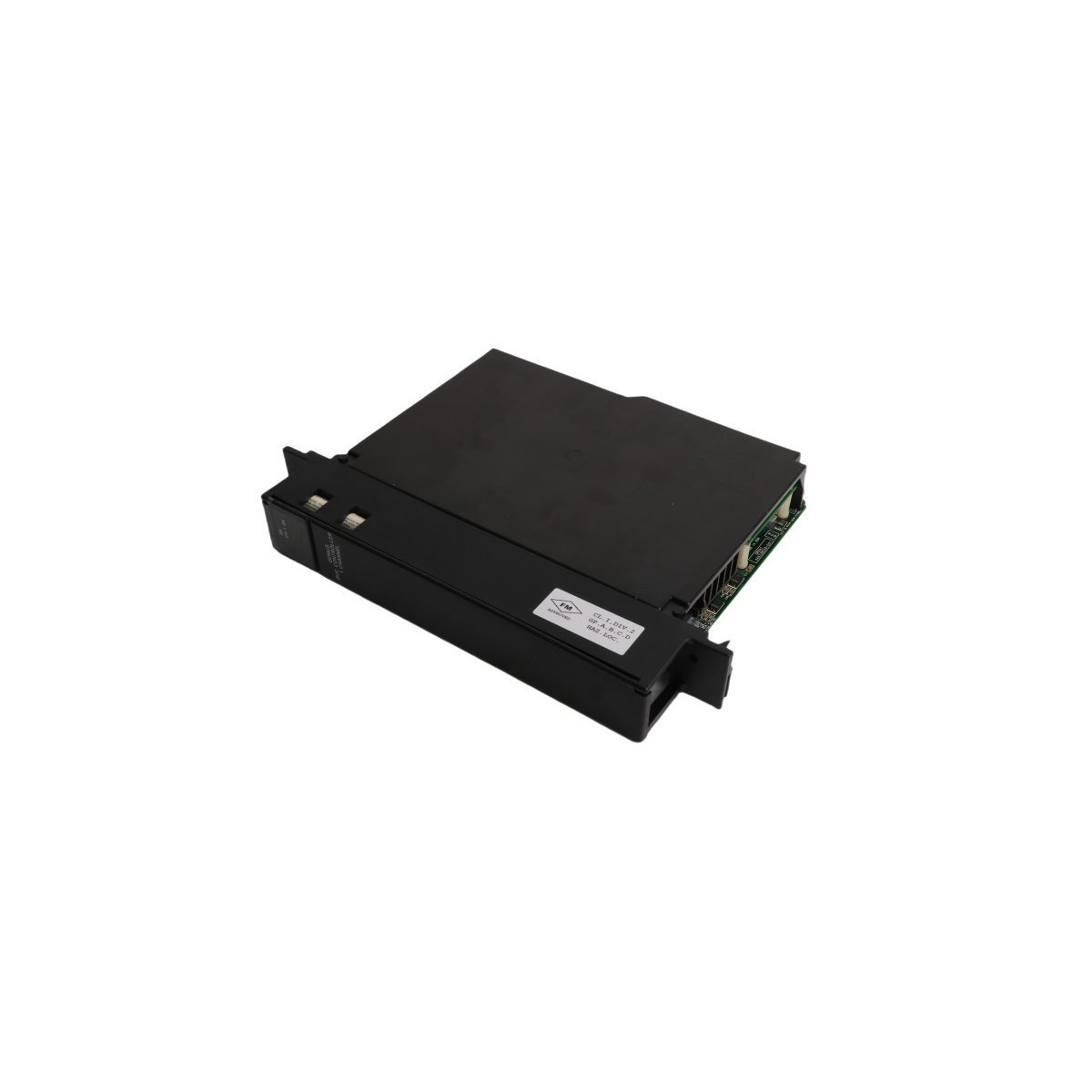
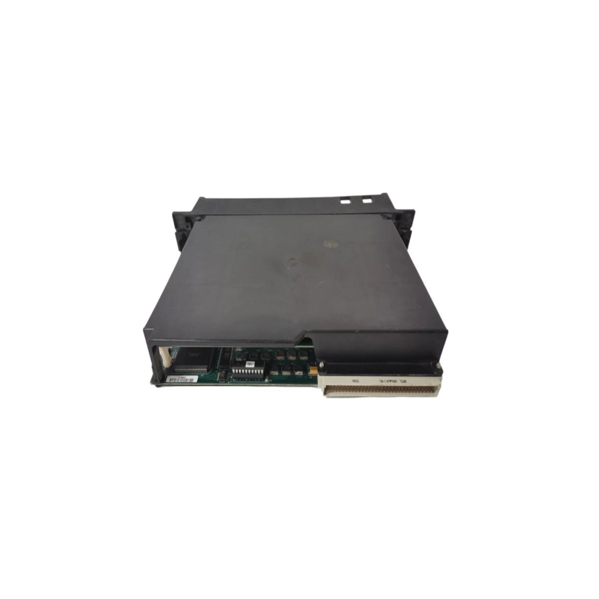
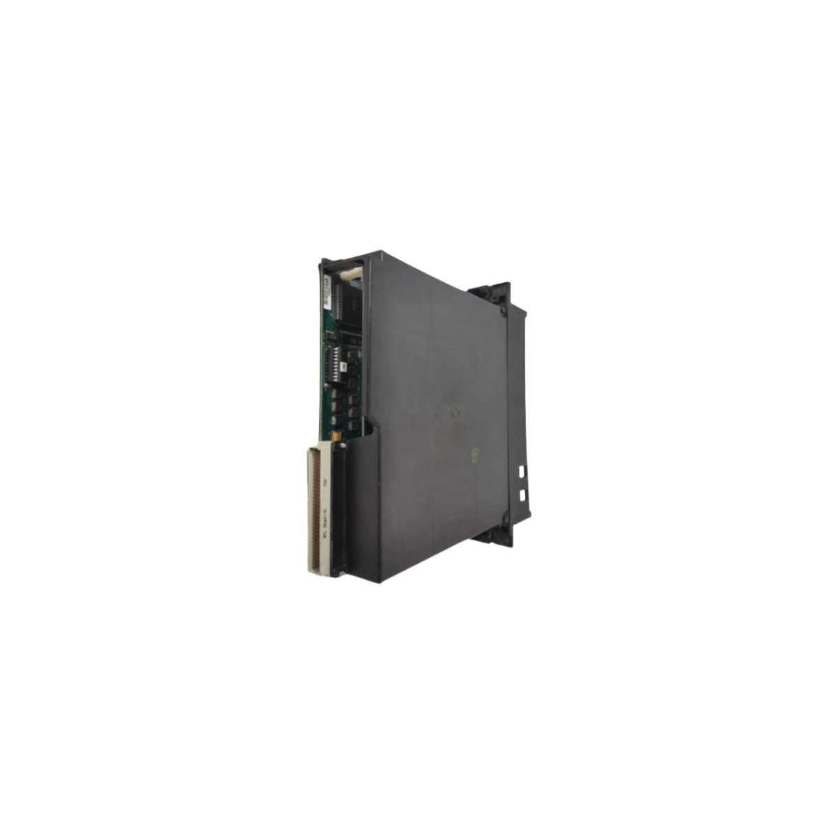
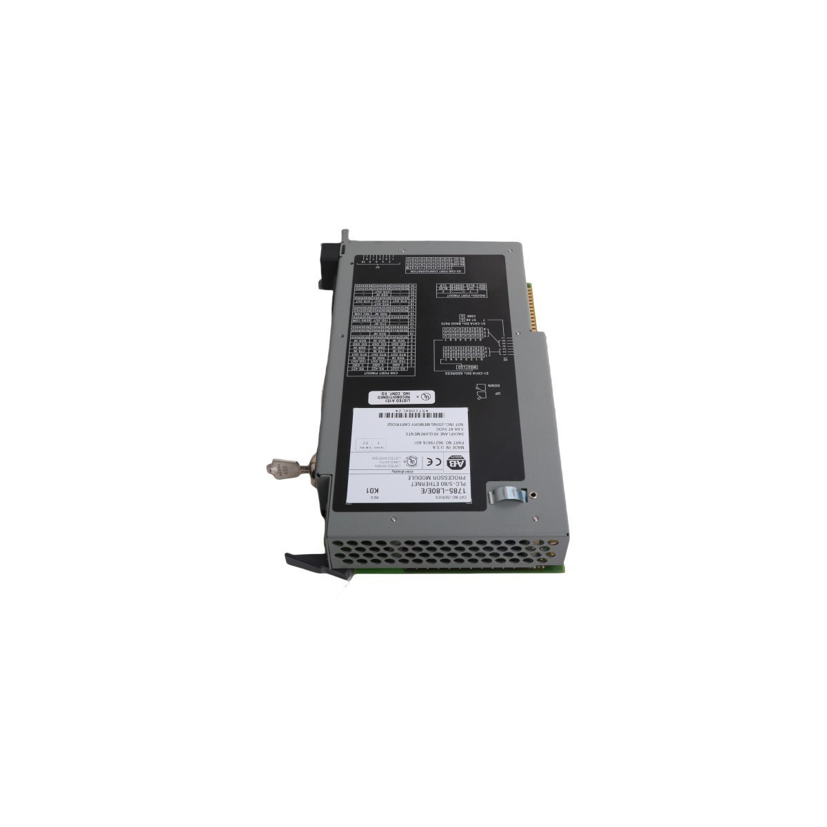
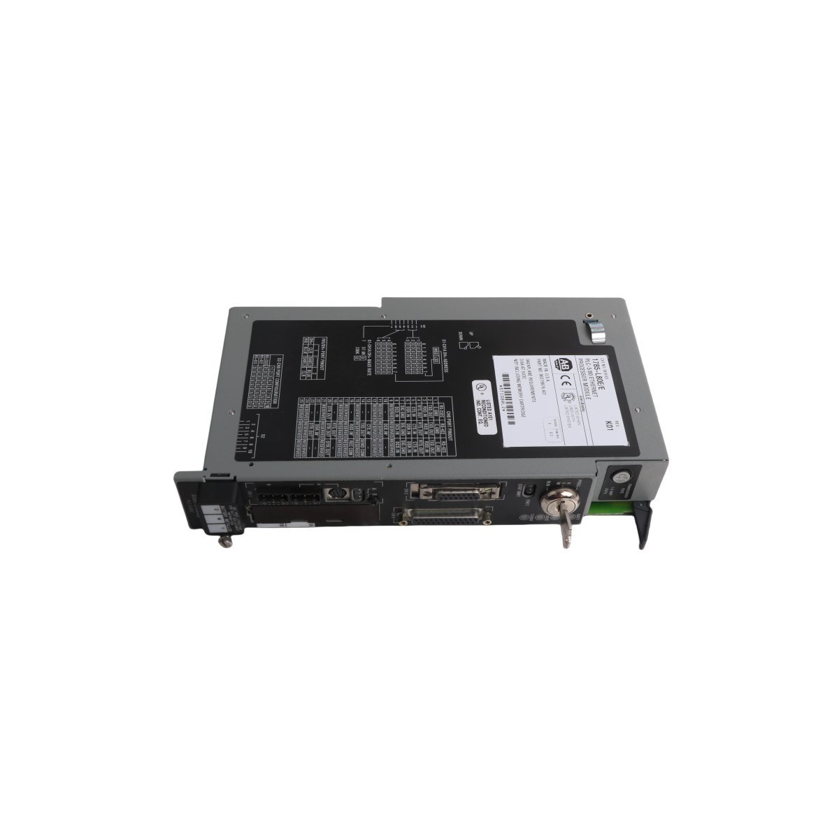
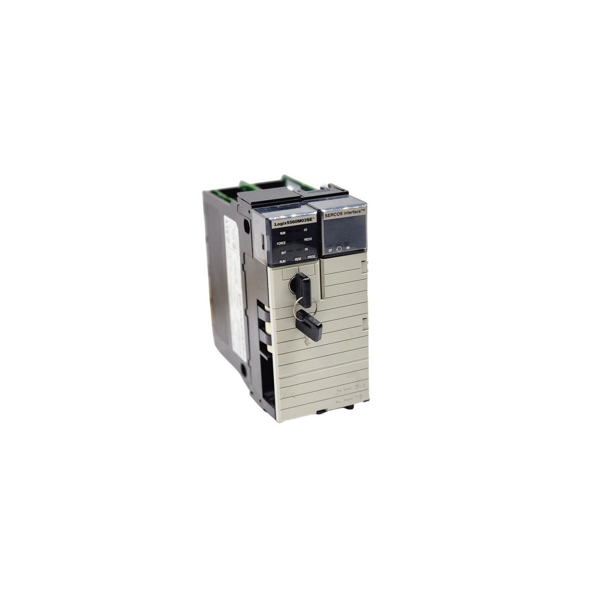
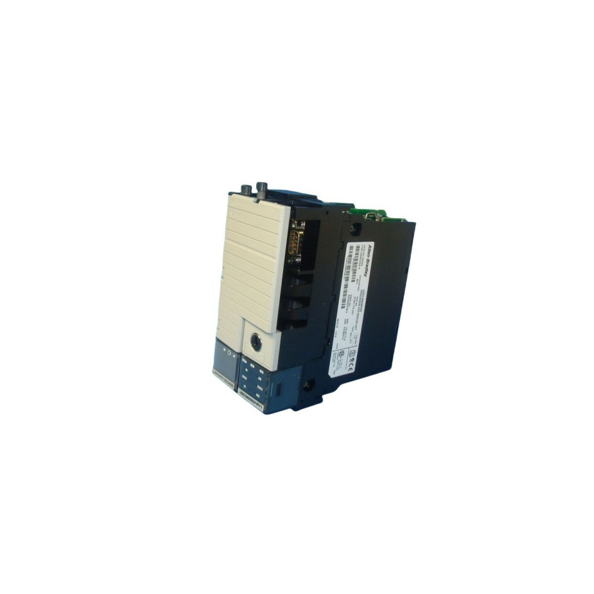
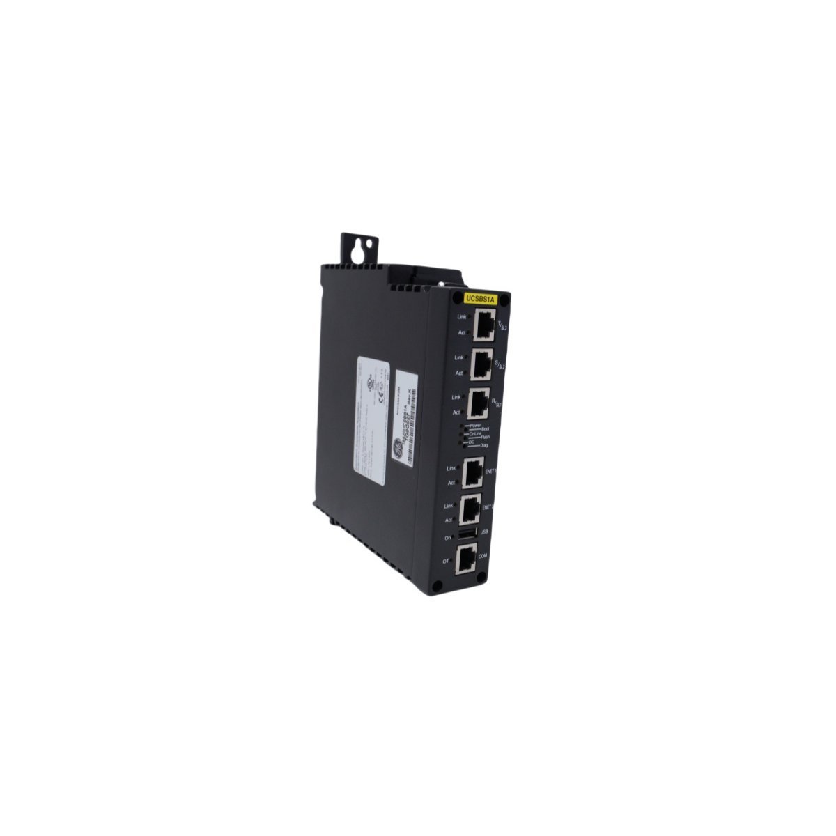
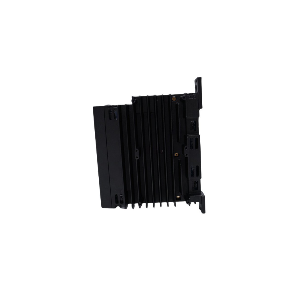
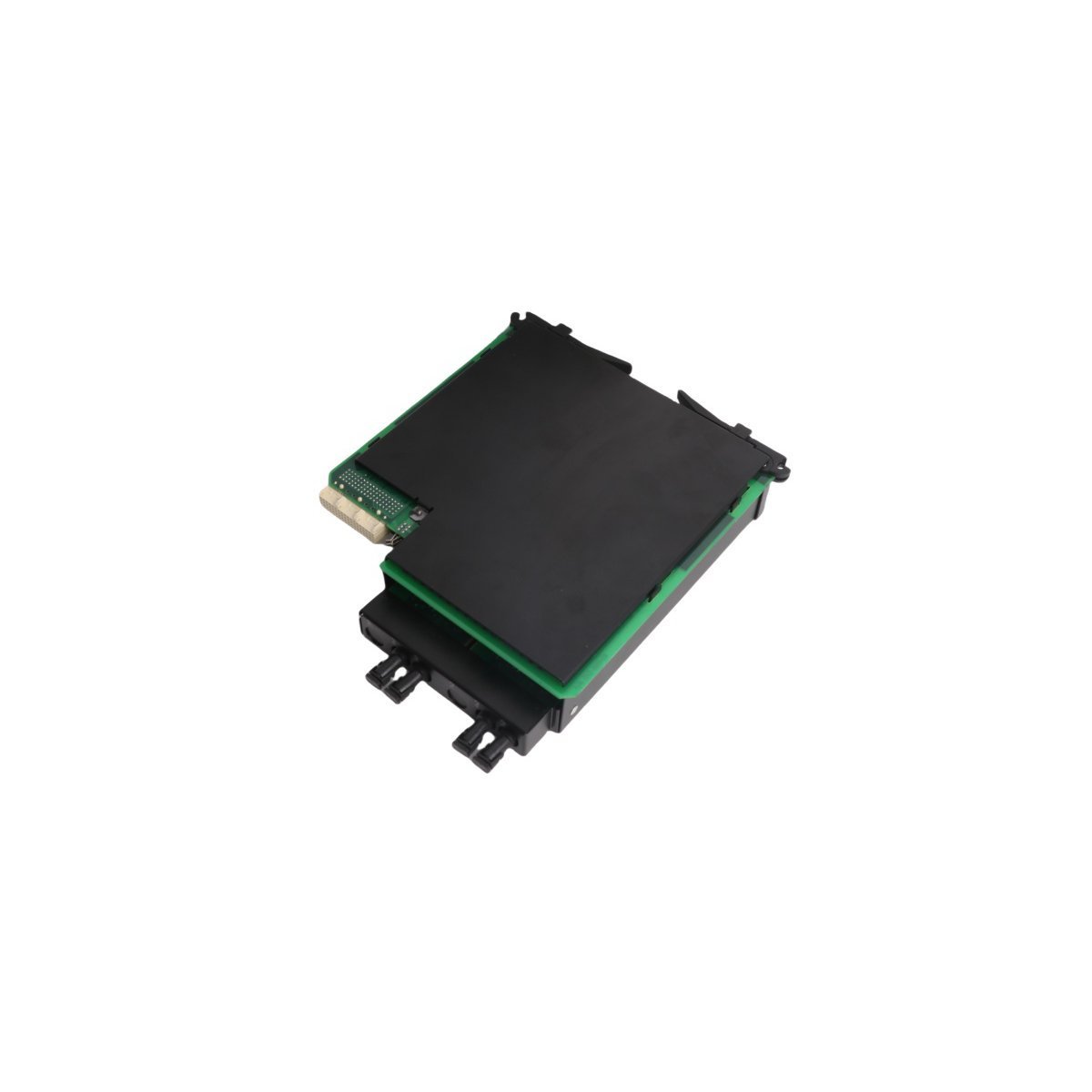
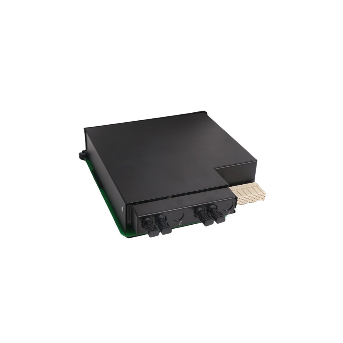
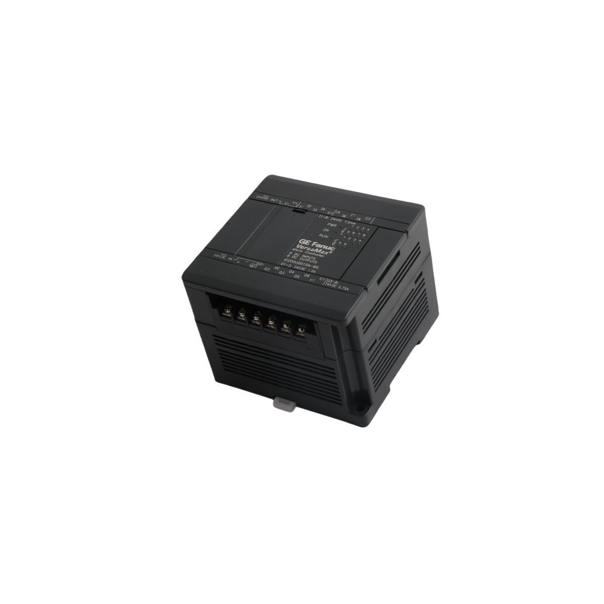
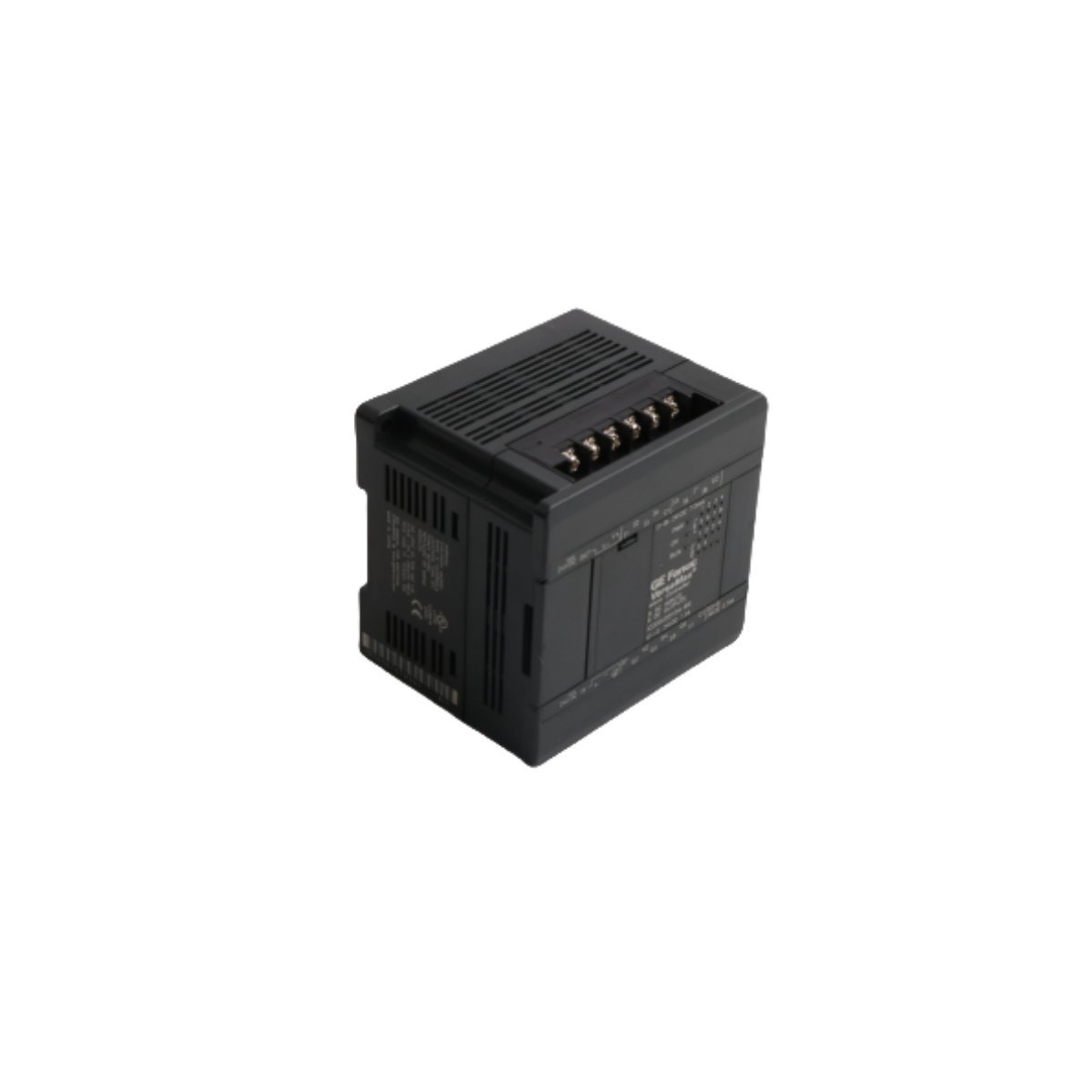
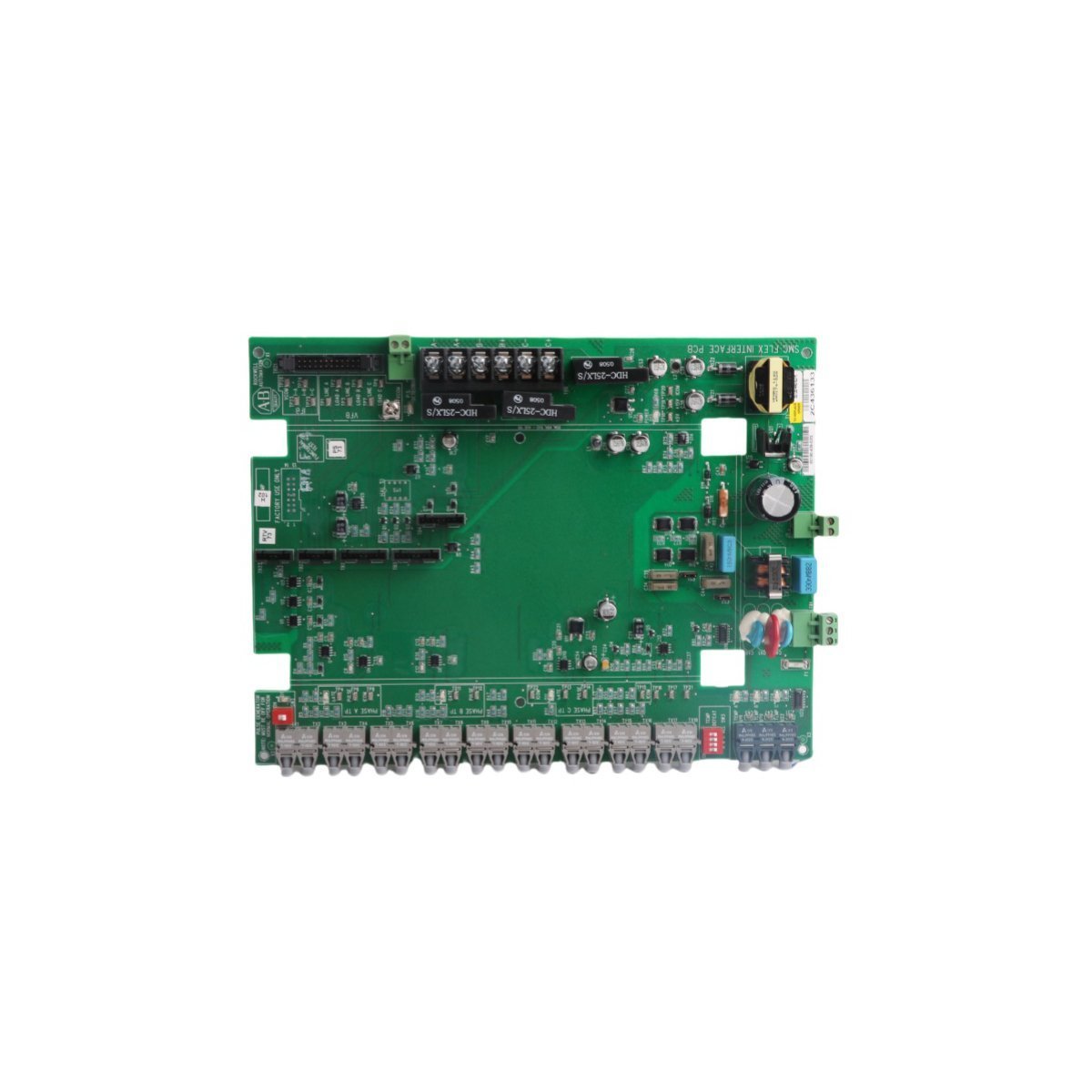
GE IC697CGR935 One Slot Controller Module
Configured for redundant processing tasks in Series 90-70 networks, the GE IC697CGR935 (IC697CGR935 One Slot Controller Module) provides direct physical and electrical execution of logic in hot-standby architectures. This controller operates with a 96 MHz 80486DX4 microprocessor to manage up to 12K discrete I/O points and 8K analog I/O points. Synchronization between primary and secondary units is maintained through backplane communication, facilitating seamless failover transitions.
Hardware Specifications
| Parameter | Specification |
|---|---|
| Model | IC697CGR935 |
| Brand | GE |
| Origin | USA |
| Weight | 0.75 kg |
| Dimensions | 4.0 cm x 21.8 cm x 29.1 cm |
| Operating Temp | 0 deg C to 60 deg C |
| Power Consumption | 3.1 A |
| Processor | 96 MHz 80486DX4 |
| Memory | 1 MB |
| Execution Speed | 0.4 microseconds (Boolean) |
Industrial Control System Performance
The IC697CGR935 relies on high-velocity backplane bus communication to ensure deterministic synchronization between redundant modules. Furthermore, firmware flash compatibility allows for controlled version updates within the Series 90-70 environment, thereby maintaining consistency across logic execution cycles. In addition, I/O density scaling is supported through the backplane interface, which enables the controller to process large datasets without exceeding defined timing constraints. Finally, Profinet and EtherNet/IP deterministic network integration requirements are managed via specific communication coprocessors when utilized in integrated automation architectures.Frequently Asked Questions
Q: What is the failover behavior if the primary controller experiences a fault?A: In a redundant pair, the secondary controller monitors the heartbeat of the primary. Upon detection of a primary fault, the secondary transitions to the active state instantaneously to prevent interruption of the process control loop.Q: Are there specific thermal requirements for operation at ambient temperatures above 50 deg C?A: Yes. Forced air cooling is required when the operating environment exceeds 50 deg C to ensure the heat dissipation of the 80486DX4 microprocessor and internal circuitry remains within specified safe limits.Field Installation Guidelines
- Ensure the rack slot is free of debris before inserting the module to guarantee proper contact with the backplane connector.
- The module must be seated flush against the rack frame and secured using the provided mounting hardware to ensure electromagnetic compatibility and grounding.
- Shielded serial cables connected to the RS232 or RS485 interfaces should be grounded at the controller end to mitigate noise interference in high-EMI environments.
- Upon initial power-up, verify that the 3-position switch is set to the correct mode (Run/Stop) and that status LEDs indicate valid processor health before establishing field I/O connectivity.