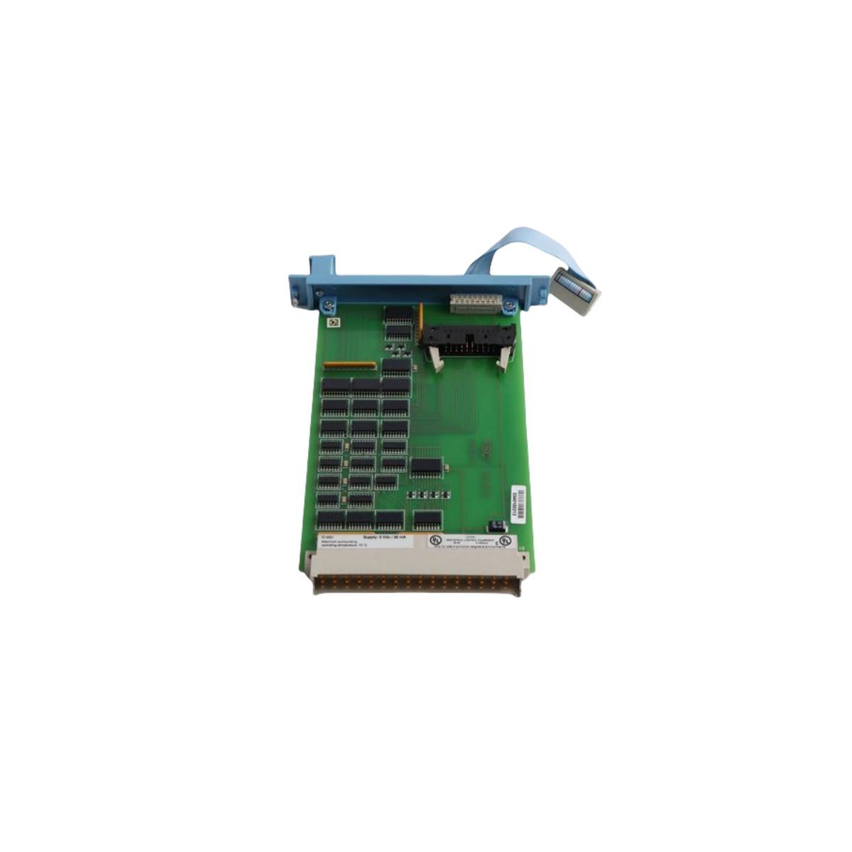
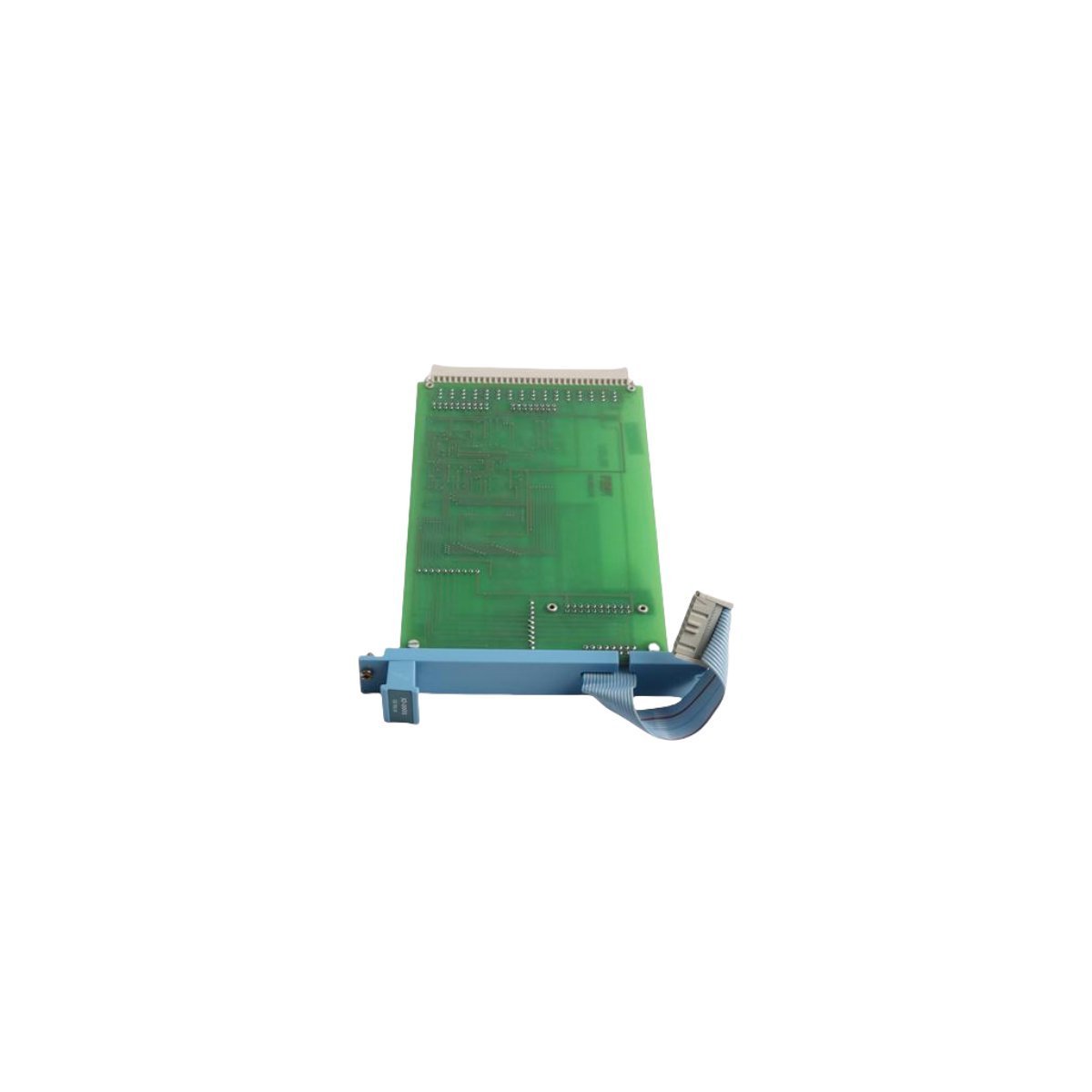
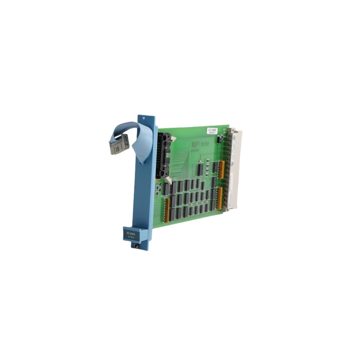
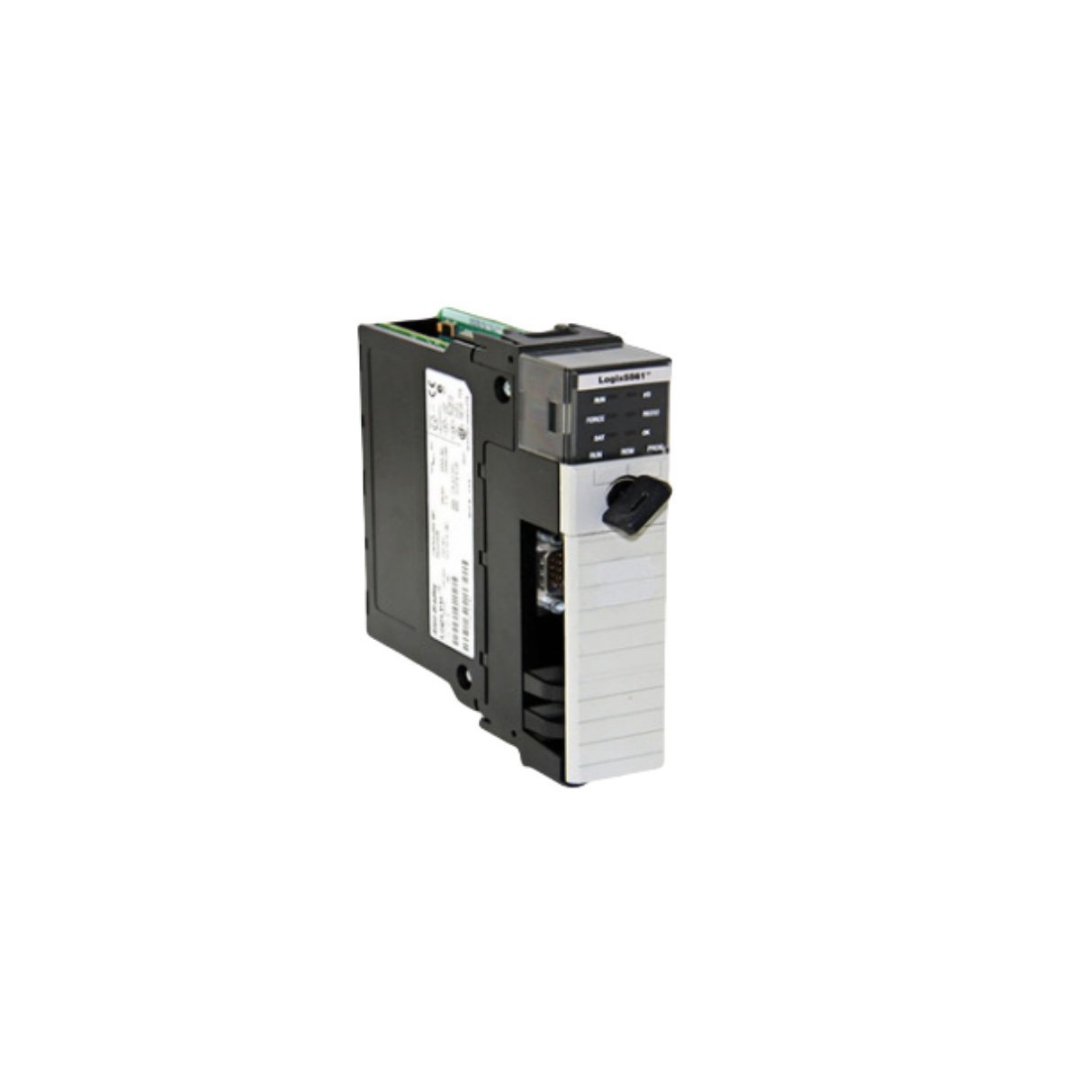
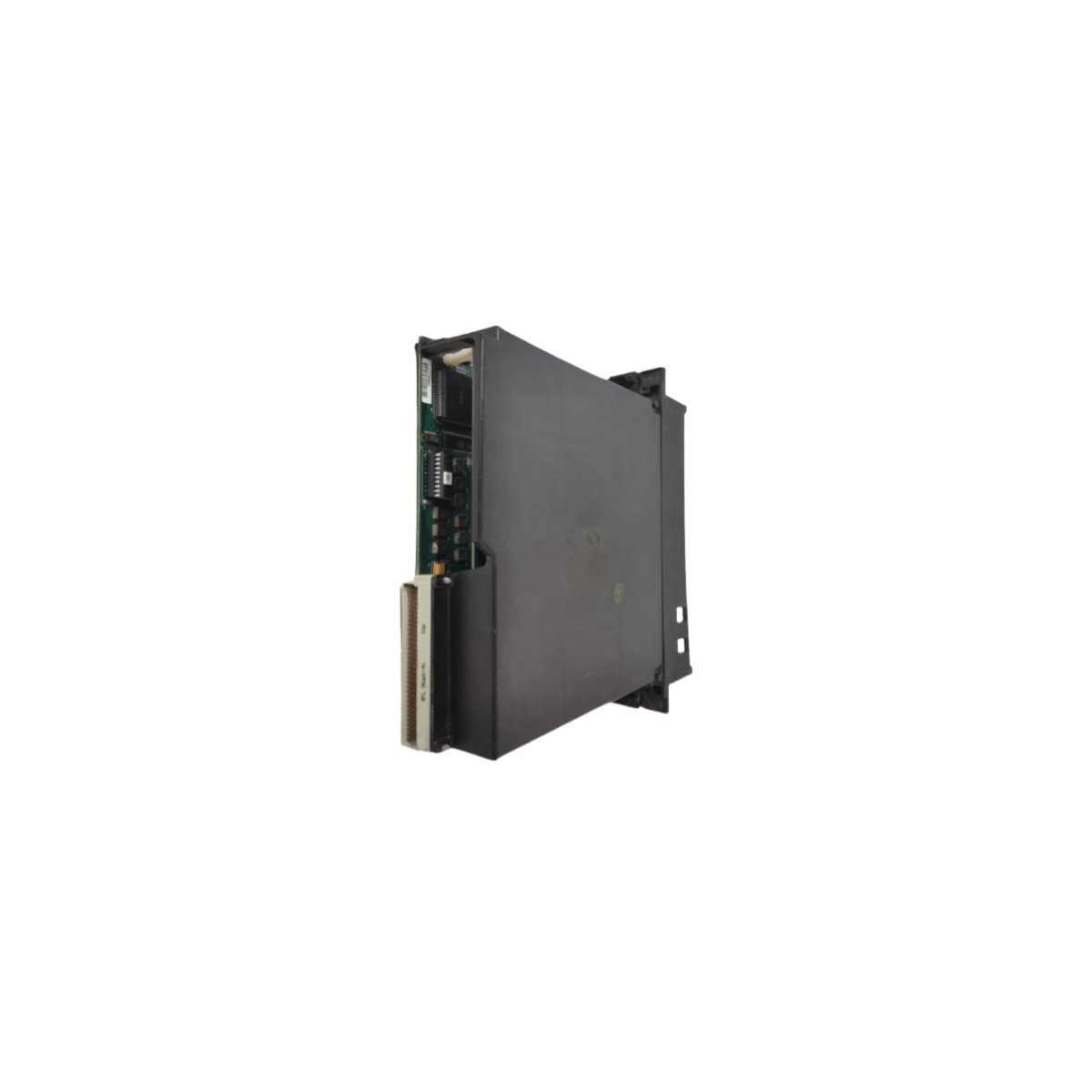
The Honeywell DC-TFB412 51307618-176, also cataloged as the DC-TFB412 Control Module, operates as a dedicated hardware component for fieldbus data routing and I/O execution within Honeywell TDC 3000 / Experion PKS DCS networks.
Hardware Specifications
Parameter
Specification
Model
DC-TFB412 51307618-176
Brand
Honeywell
Origin
USA
Weight
0.5 kg
Dimensions
10 x 18 x 10 cm
Operating Temp
0 to 60 deg C
Power Consumption
System Backplane Bus Powered
Module Type
Control Module / Field Termination Assembly
System
DCS / Safety System
Communication Service
Ethernet Router / Fieldbus
HS Code
8537101190
Process Loop Signal Conditioning & Channel Isolation
Configured for high-density field integration, the assembly processes 4-20 mA HART loop protocol communications across distribution channels. Channel-to-channel isolation safeguards sensitive analog input circuits from ground loops and external common-mode voltage spikes. The module incorporates cold junction compensation (CJC) for high-accuracy temperature measurement circuits, maintaining signal accuracy and bus stability across changing ambient environmental operating conditions.
Frequently Asked Questions
Q: How does channel-to-channel isolation protect field instrumentation loops?
A: Physical galvanic isolation breaks potential ground loop paths between separate field devices, preventing ground differential noise from corrupting 4-20 mA HART signal lines.
Q: Is field wiring termination handled directly on the control module assembly?
A: Connection interface terminals route field signal lines directly into the termination assembly, converting field-side cabling into structured backplane communication signals.
Field Installation Guidelines
Cabinet Power Demarking: De-energize cabinet power lines or ensure system rack bus isolation prior to inserting or removing module connection assemblies.
Shield Grounding Alignment: Terminate signal cable shields at a single ground point to prevent stray circulating ground currents from inducing noise on low-level analog transmission lines.
Cabinet Ventilation Requirements: Mount modules with a minimum vertical clearance of 50 mm above and below the chassis to maintain adequate convective air flow within the enclosure.
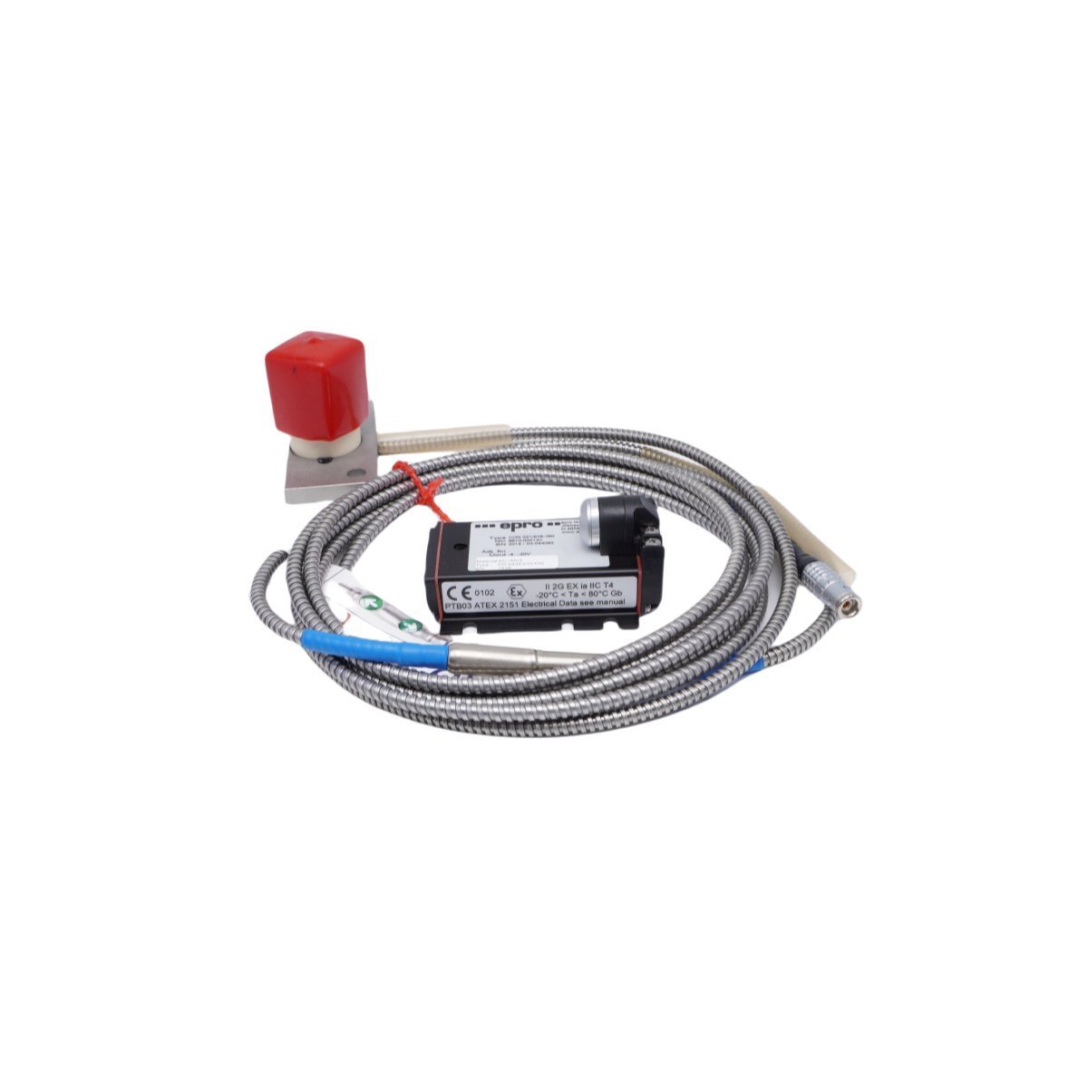
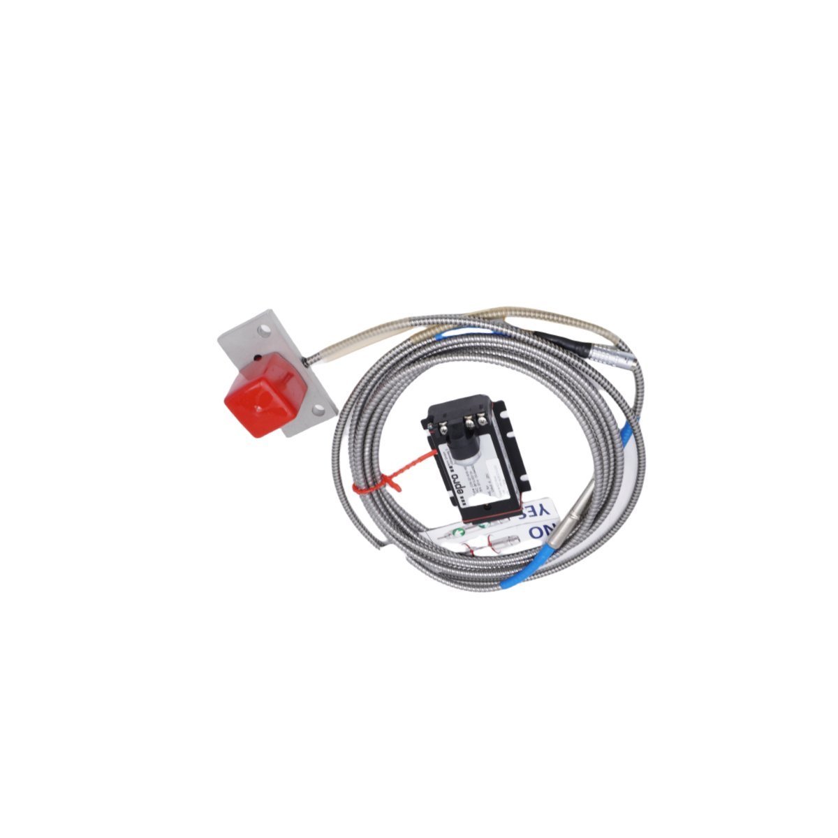
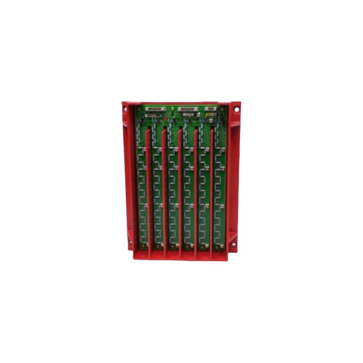
The Emerson PR6426/010-000 CON021, also cataloged as the PR6426/010-000 CON021 Controller Module, operates as a dedicated hardware component for analog process signal conditioning and control loop execution within distributed control platforms.
Hardware Specifications
Parameter
Specification
Model
PR6426/010-000 CON021
Brand
Emerson
Origin
USA
Weight
0.54 kg
Dimensions
22 x 18 x 4.5 cm
Operating Temp
0 deg C to 60 deg C
Power Consumption
24 VDC nominal
Process Loop Integration and Signal Isolation
The module processes analog inputs through dedicated signal conversion channels while maintaining channel-to-channel isolation to prevent electrical interference across loops. The internal circuitry supports 4-20 mA HART loop protocol integration for remote transmitter calibration and real-time diagnostic polling. Cold junction compensation (CJC) maintains thermocouple measurement accuracy across ambient temperature shifts, while FOUNDATION Fieldbus communication layers execute deterministic field device updates without loop degradation.
Frequently Asked Questions
Q: Does the module support live insertion and removal under power?A: System backplane specifications dictate whether hot-swapping is permitted; verify rack-level power status before extracting the module to prevent backplane bus faults.Q: How are field wiring errors isolated from internal processor components?A: Channel-to-channel galvanic isolation circuits prevent transient overvoltages from propagating across adjacent analog input channels or damaging internal logic planes.
Field Installation Guidelines
Mount the unit securely within designated enclosure slots, ensuring that shielded twisted-pair cables terminate at the proper grounding bars to minimize electromagnetic interference. Verify loop supply voltage levels prior to terminal block connection to protect analog input stages against overvoltage conditions.
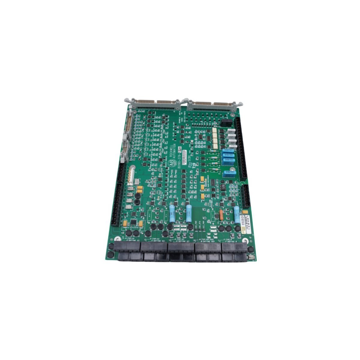
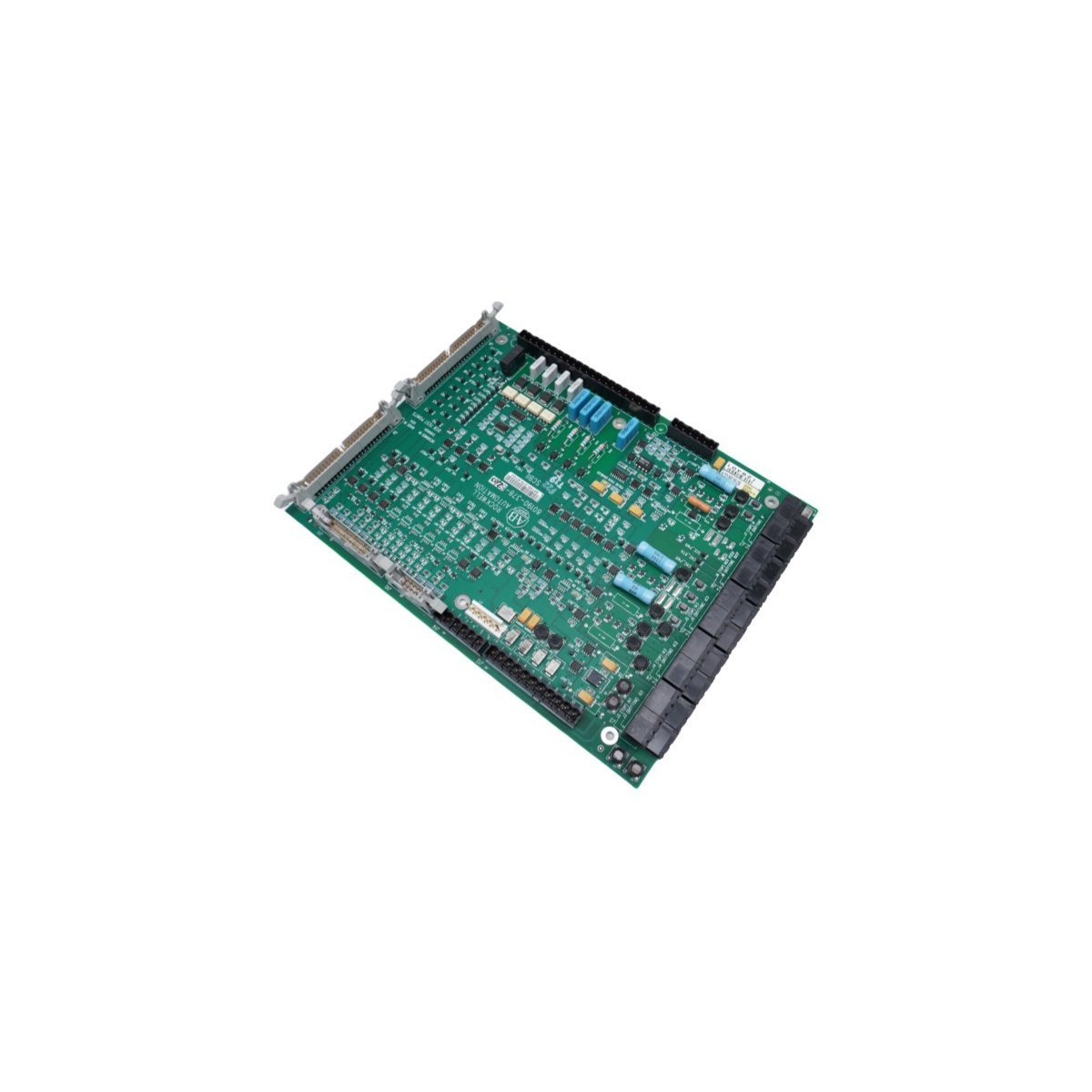
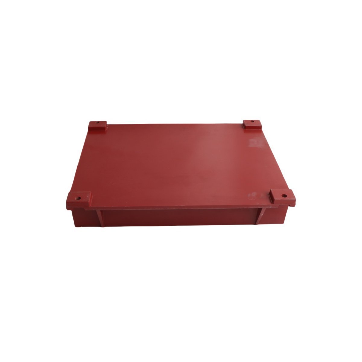
The Allen Bradley 80190-378-52, also cataloged as the 80190-378-52 Inverter Control Board, operates as a dedicated hardware component for inverter logic processing and signal regulation within PLC-5 platform networks.
Hardware Specifications
Parameter
Specification
Model
80190-378-52
Brand
Allen Bradley
Origin
USA
Weight
0.46 kg
Dimensions
27.8 x 21.4 x 2.8 cm
Operating Temp
Standard Industrial Range
Power Consumption
System Dependent
Module Type
Inverter Control Board
Industrial Control System Integration
The Allen Bradley 80190-378-52 utilizes backplane bus communication protocols designed for integration with PLC-5 control architectures. The module supports deterministic network timing, ensuring low-latency state feedback and synchronization within complex I/O density configurations. Compatibility with field-programmable firmware allows for flash updates to align with evolving backplane bus communication velocity requirements, maintaining bus traffic integrity and reducing collision potential in high-speed control loops.
Frequently Asked Questions
Q: What are the restrictions regarding the installation of the 80190-378-52 in an active PLC-5 backplane?A: Ensure that backplane power is cycled off before module insertion or removal to prevent electrical arcing on connector pins. The module must be firmly seated in the chassis slot to maintain signal integrity across the backplane bus.Q: Is this module capable of firmware field-upgrades?A: Yes, the unit supports firmware flash compatibility via the primary control bus interface. Verify the current revision against the specific PLC-5 processor requirements before initiating any update sequence.
Field Installation Guidelines
Mount the control board into the designated PLC-5 chassis slot. Tighten the mounting screws to the specified torque to guarantee a secure electrical chassis ground connection.
Avoid exposing the component to electrostatic discharge (ESD). Utilize a grounded wrist strap at all times when handling the board.
Ensure all backplane pins are clean and free of debris or oxidation prior to installation.
Maintain ambient operating temperature within the specified industrial limits to prevent thermal degradation of on-board components.
Verify that the backplane power supply capacity is sufficient for the total I/O density load when the module is fully initialized.
The Allen-Bradley 1756-L55M24 is a high-performance GuardLogix controller offering 3.5 MB of non-volatile memory for integrated safety, motion, and discrete control applications.
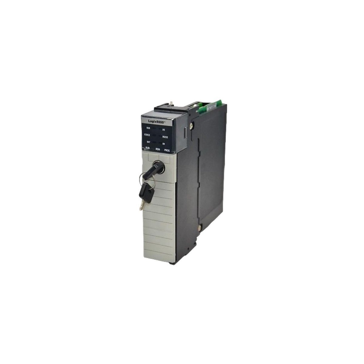
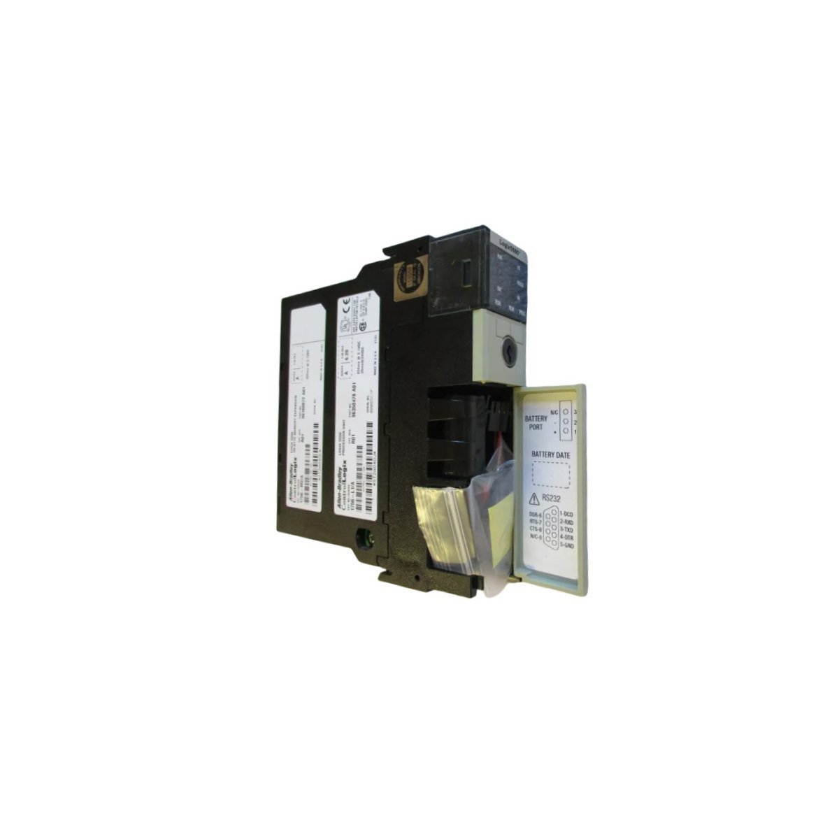
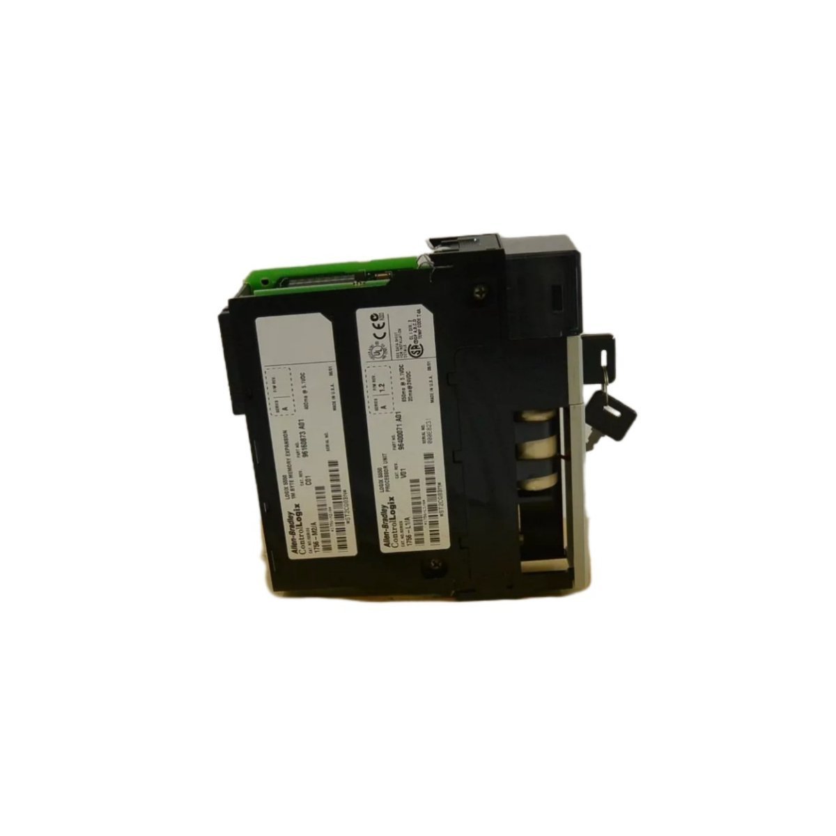
The Allen-Bradley 1756-L1M2 is a 1 MB ControlLogix 5550 processor module designed to manage high-speed logic and network communication in industrial control systems.
The GE IC697CPX928 is a powerful 96MHz CPU module for Series 90-70 PLC systems. It supports high-density I/O, advanced floating-point math, and large memory storage.
The Allen-Bradley 81001-355-71-R is a high-performance Silicon Controlled Rectifier module engineered for reliable power regulation and industrial switching tasks.
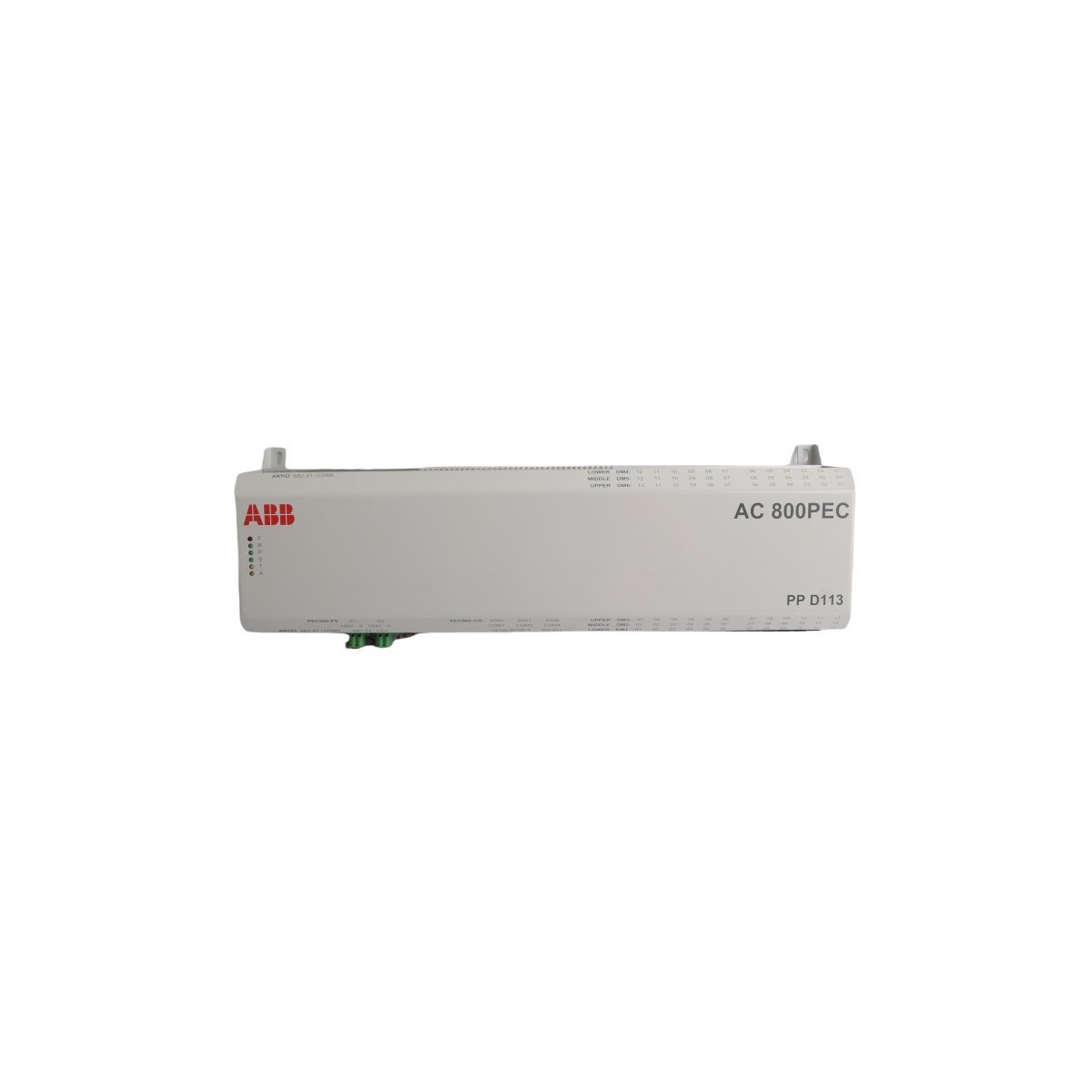
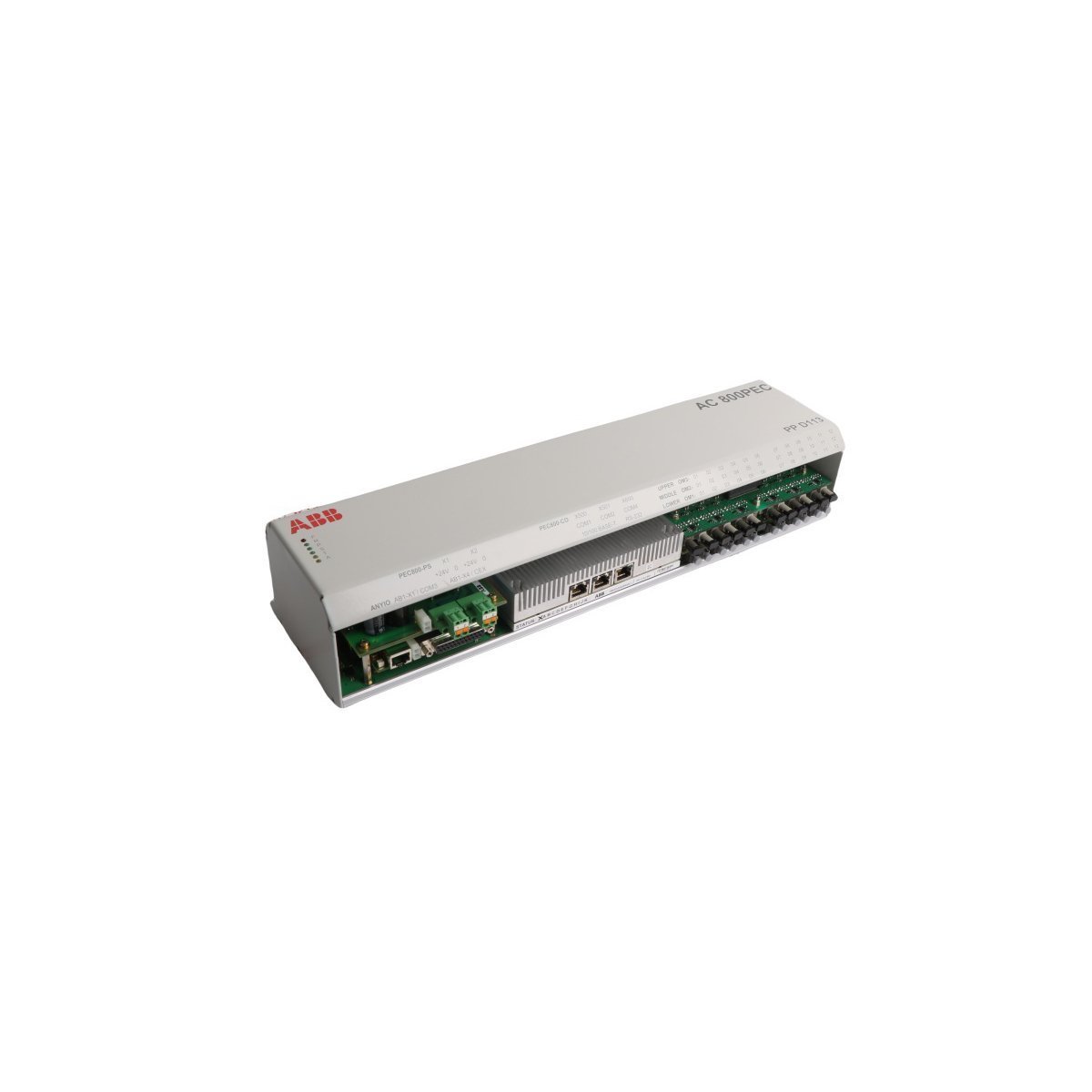
The ABB PPD113 3BHE023784R2630 is a high-speed control module for the AC 800PEC system. It features advanced adaptive control technology and high-performance processing capabilities, making it ideal for complex power electronics and DCS applications requiring maximum reliability.
The GE IS215UCCCH4A is a 1.6 GHz Intel Pentium M-powered VME controller board for Mark VIe systems. Featuring 256MB DRAM and QNX Neutrino OS, this 3U CPCI module provides high-speed processing and robust diagnostics for gas turbine control.
The GE IS420UCSDS1 is a 600 MHz UCSB controller module for the Mark VIe system. Designed for high-reliability turbine control, it features an Intel processor, dual/TMR redundancy support, and ATEX Zone 2 certification for demanding industrial environments.
The HIMA F6205 is a professional 16-channel relay control module for H41q and H51q safety systems. Featuring 16 SPST relays rated at 10A/24VDC, this German-engineered module provides robust galvanic isolation and reliable switching for high-power industrial actuators in safety-critical applications.
The Allen-Bradley 1785-L30B is a 32K-word PLC-5/30 controller module designed for high-density automation.It supports 1024 I/O points and features dual DH+/Remote I/O ports alongside a multi-protocol serial interface, ensuring reliable distributed control for complex industrial applications.
The Bachmann LX700/DD256/CF512MB is a high-speed central processor for the M1 system, featuring 256MB RAM and 512MB Flash storage.Providing dual Ethernet ports and a real-time VxWorks environment, it serves as the robust intelligence core for utility-scale renewable energy and maritime automation projects.
We are committed to protecting your privacy. The information collected here is strictly used to provide the requested quotes, technical support, and relevant industrial automation solutions.