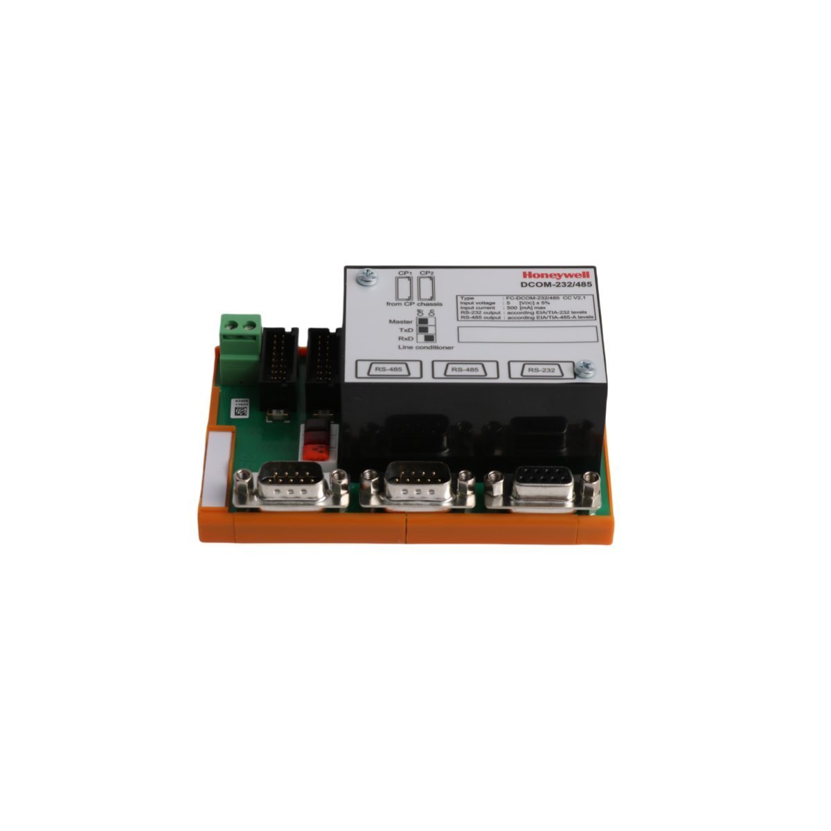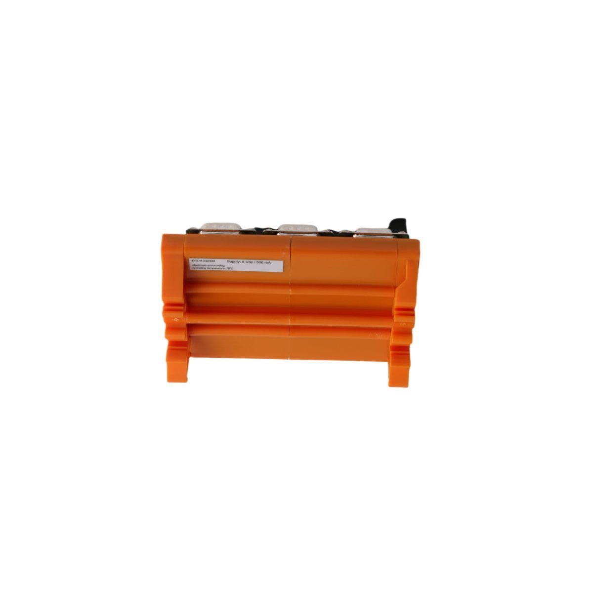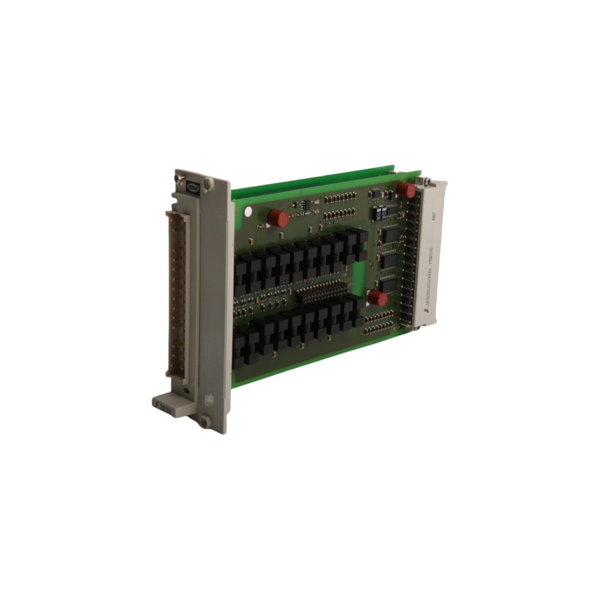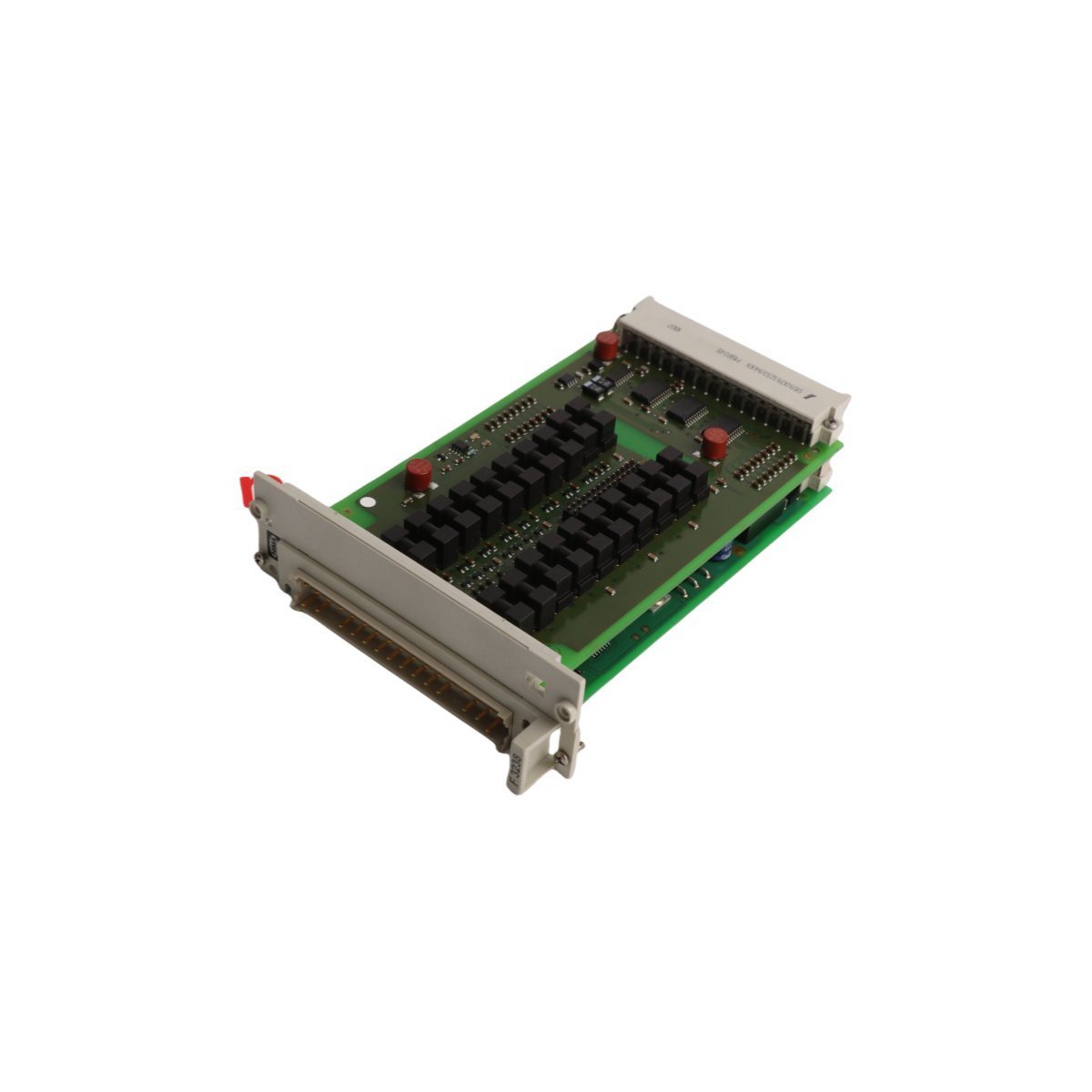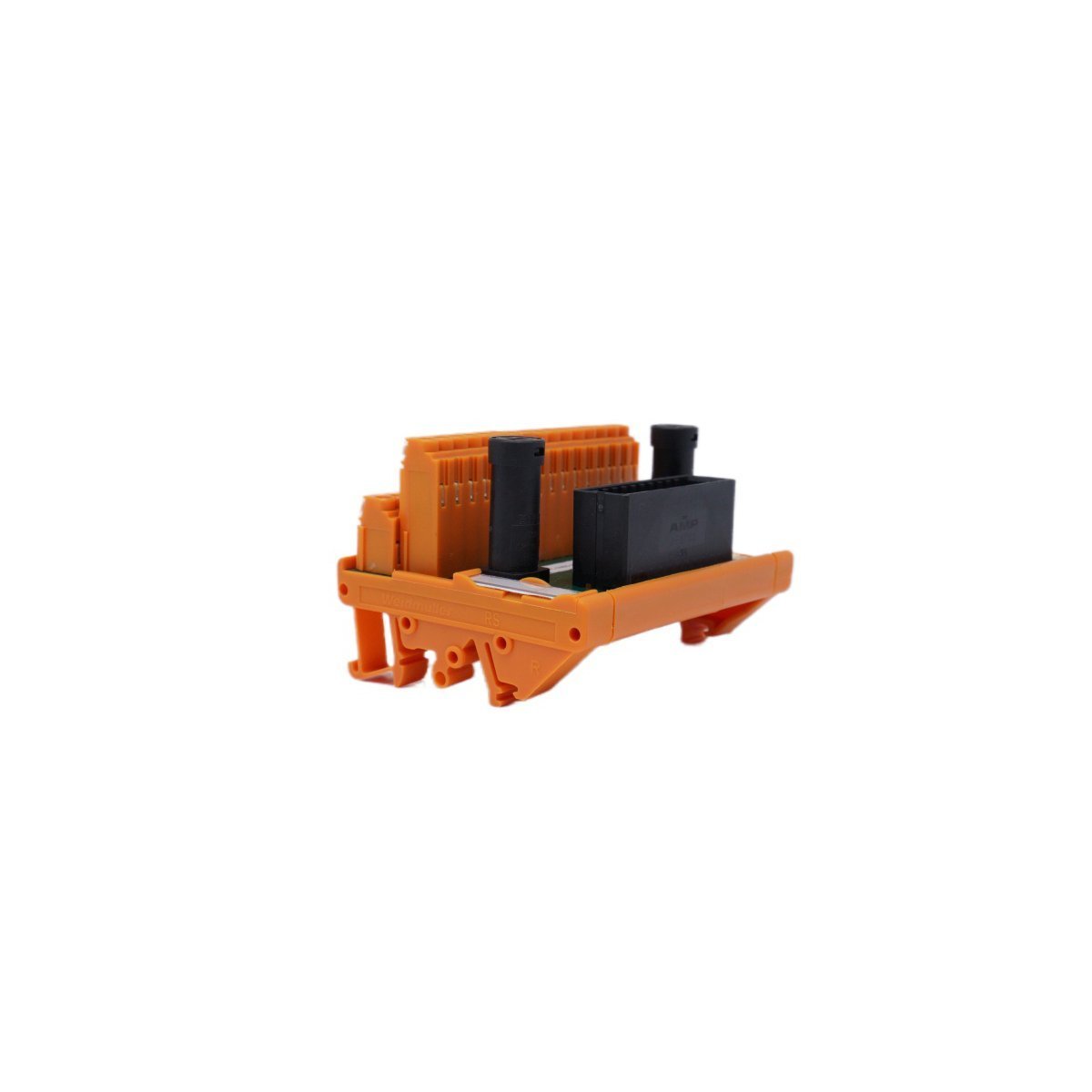
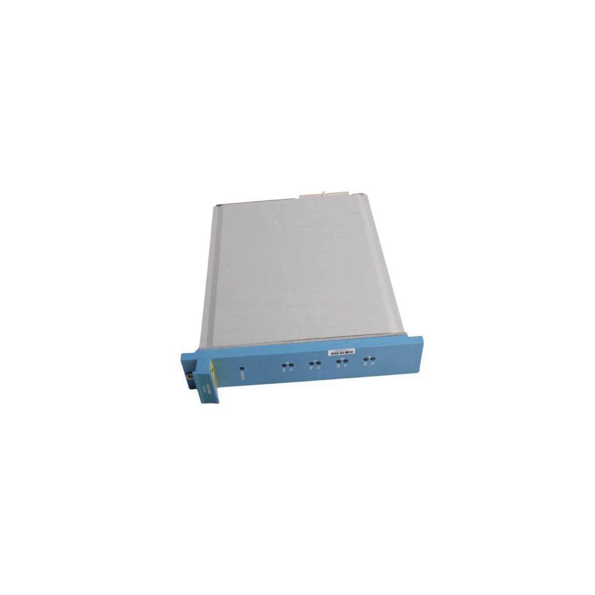
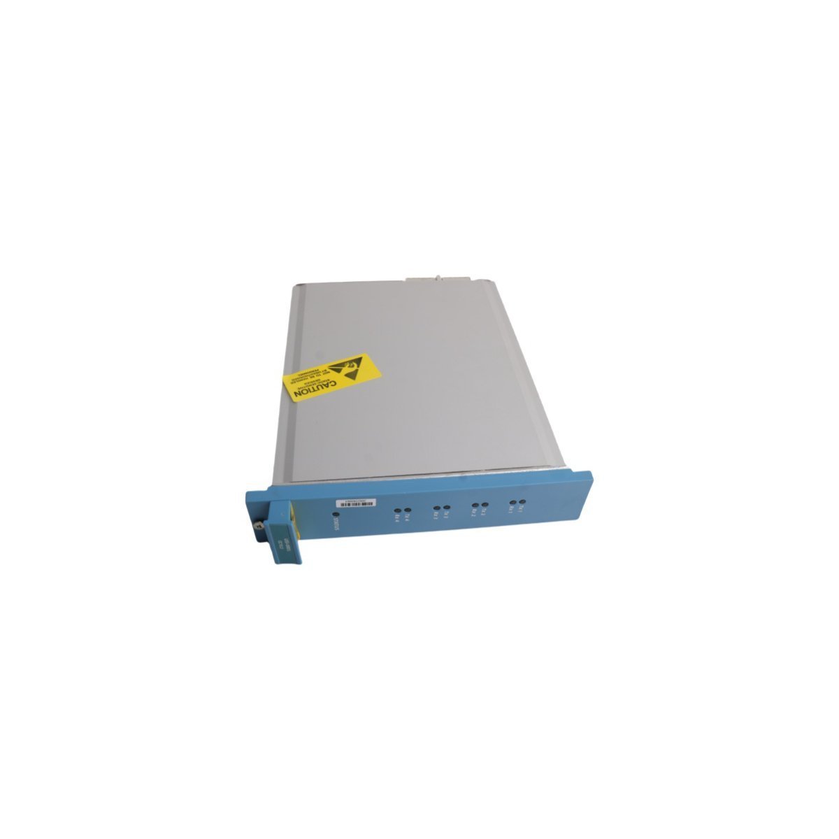
Honeywell FC-USI-0001 V1.3 Universal Safety Interface CC
Hardware Specifications
| Parameter | Specification |
|---|---|
| Model | FC-USI-0001 V1.3 |
| Brand | Honeywell |
| Origin | USA |
| Weight | 0.72 kg |
| Dimensions | 3.5 x 22.5 x 17.4 cm |
| Operating Temp | 0 to 60 deg C |
| Power Consumption | Standard Backplane Bus Drain |
| Product Series | Safety System / Safety Manager |
| Module Type | Universal Safety Interface CC |
| System | DCS / SIS |
| Status | Active |
| HS Code | 8537101190 |
Process Isolation and HART Loop Interface Protocols
The FC-USI-0001 V1.3 provides galvanically isolated signal conditioning and communication translation between field process instrumentation and safety controller processing nodes. It supports standard 4-20 mA HART loop protocol pass-through, enabling bi-directional digital device configuration and real-time diagnostic extraction without interrupting critical safety instrumented function (SIF) logic execution.Each I/O path incorporates dedicated channel-to-channel isolation circuits to prevent stray ground loop currents from propagating across the internal system bus. Integrated cold junction compensation (CJC) processing algorithms maintain precise temperature and analog voltage scaling across environmental temperature variations within the control cabinet.Frequently Asked Questions
Q: Does the FC-USI-0001 V1.3 support online module replacement while the safety system is energised?A: Module replacement under power is permissible provided the active safety rack environment complies with system hot-swap restrictions and ESD protective grounding protocols are maintained.Q: How does channel-to-channel isolation function on the FC-USI-0001 V1.3 interface board?A: Transformer and optocoupler galvanic isolation barriers isolate each individual channel circuit, suppressing electrical transients and preventing field-side voltage spikes from damaging central rack processors.Field Installation Guidelines
First and foremost, disconnect upstream power feeds and verify complete cabinet de-energization prior to mounting or swapping safety interface hardware.
Next, align the FC-USI-0001 V1.3 circuit board assembly with the chassis card guides and carefully slide the module inward until the backplane connectors mate completely.
Subsequently, fasten top and bottom retaining hardware to secure mechanical bonding and maintain continuous ground continuity with the system rack enclosure.
Following hardware securing, route field wiring cable harnesses through dedicated wireways, ensuring analog signal lines are physically separated from high-voltage AC distribution circuits.
Finally, apply power to the rack chassis while continuously monitoring diagnostic LEDs to confirm successful POST completion and active communication status with the host safety controller.