
Sale!
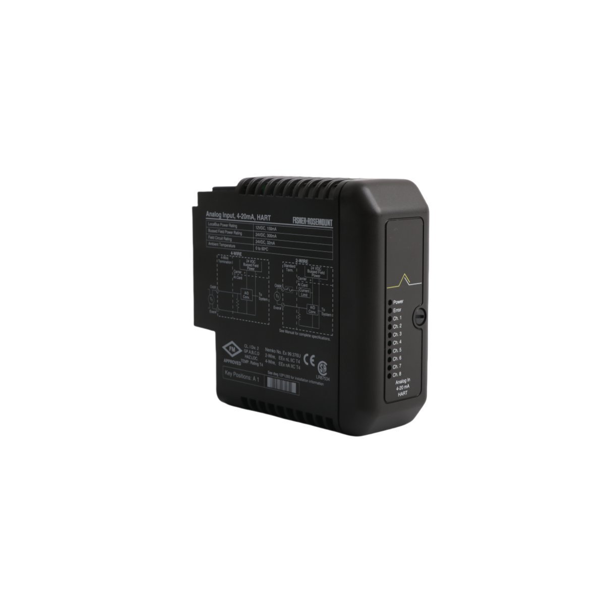
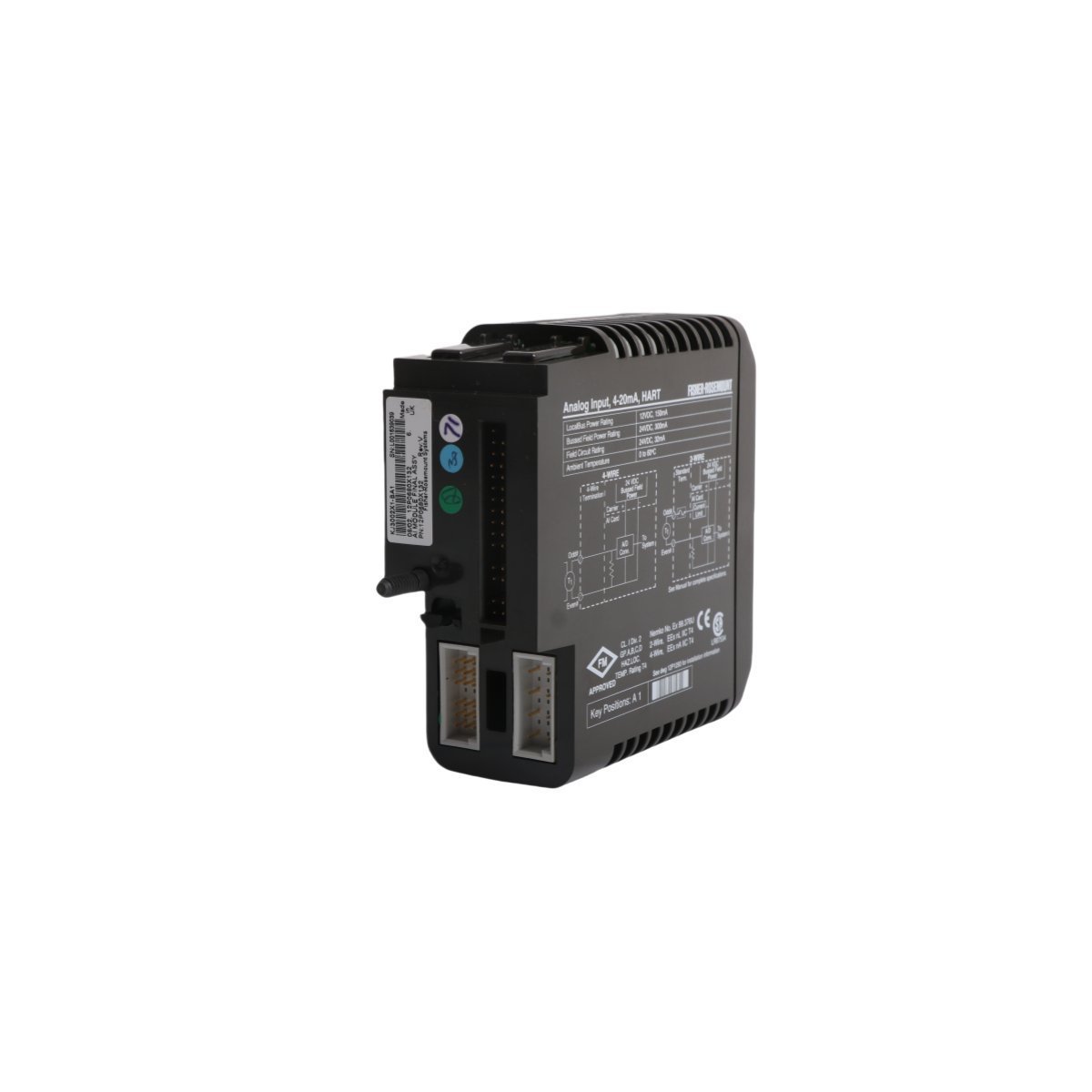
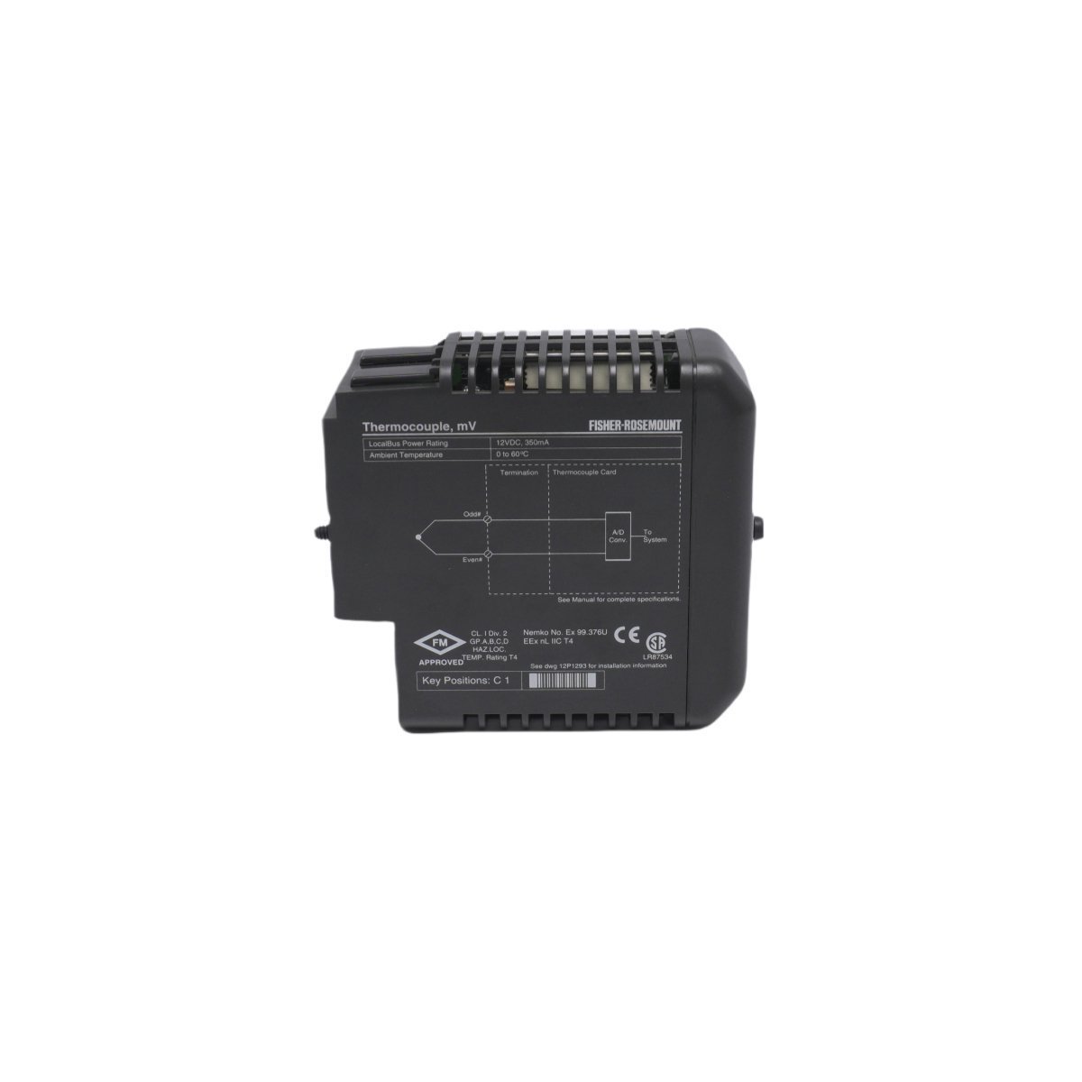
EMERSON KJ3002X1-BA1 DeltaV M-series I/O Subsystem
Get technical data for the EMERSON KJ3002X1-BA1 analog module. Brand New, Original Stock, with Global Shipping options.
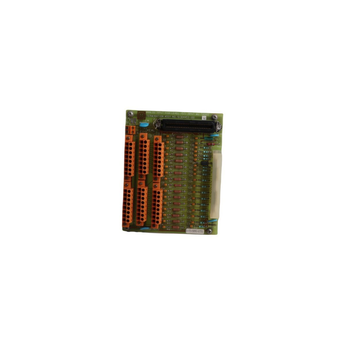
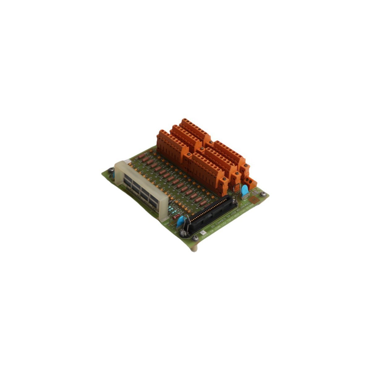
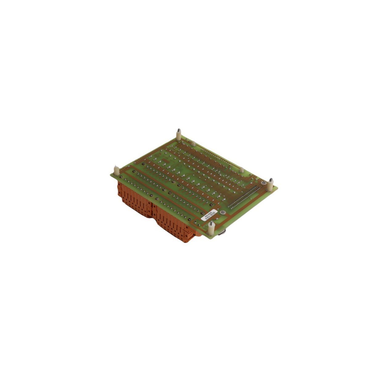
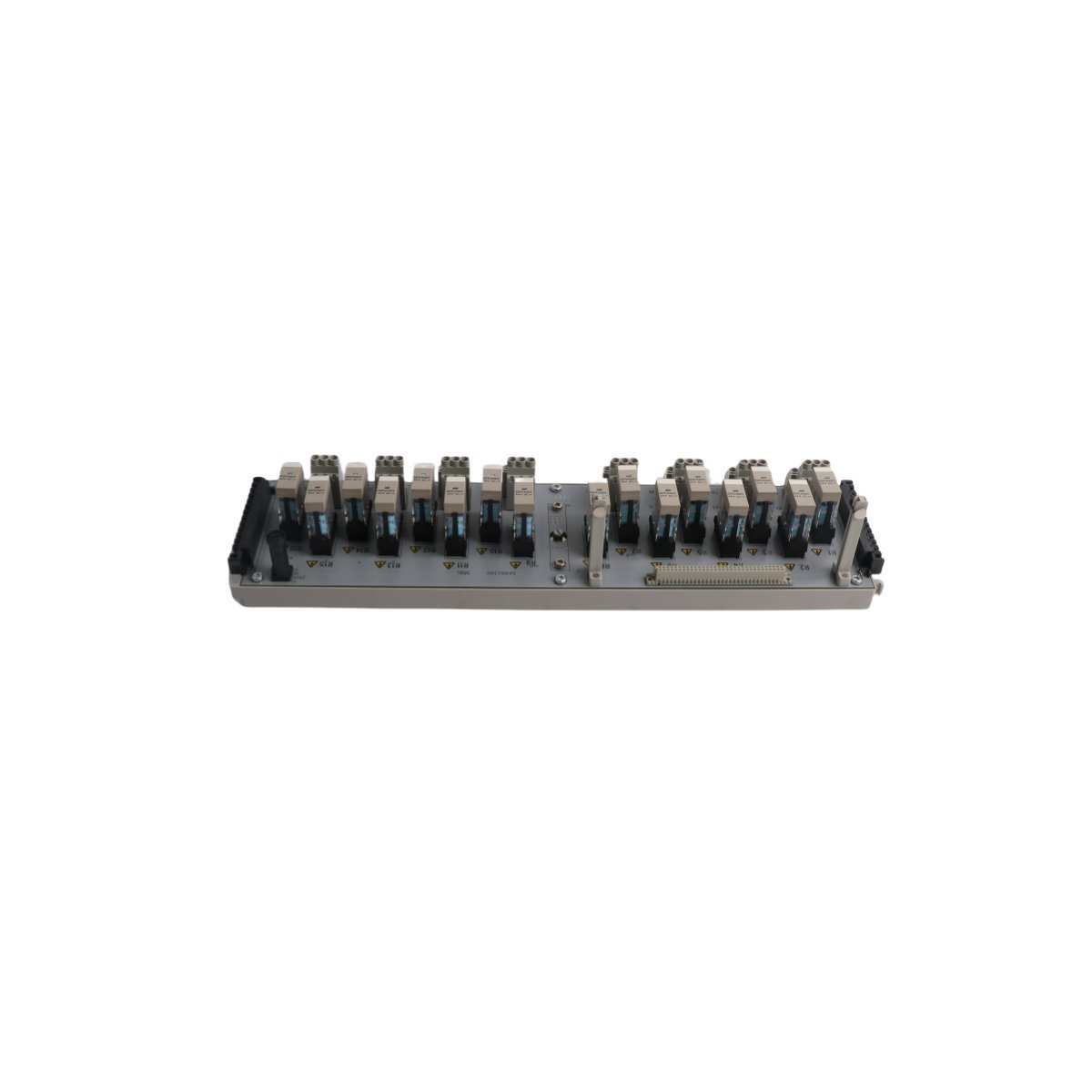
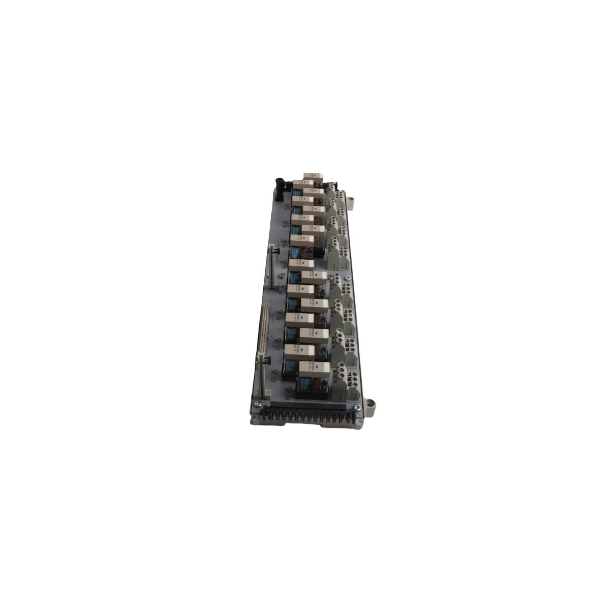
Configured for signal interface execution in DCS platforms, the Honeywell MU-TAIH02 51304453-100 (MU-TAIH02 Analog Input STI Termination Board) provides direct physical signal termination.
| Parameter | Specification |
|---|---|
| Model | MU-TAIH02 51304453-100 |
| Brand | Honeywell |
| Origin | USA |
| Weight | 0.34 kg |
| Dimensions | 12.1 cm x 5.5 cm x 15.2 cm |
| Operating Temp | Consult system environmental specs |
| Power Consumption | Determined by I/O load |
| Channel Capacity | 16 channels |
| Compatibility | MU-T Series DCS |
This termination board facilitates field wiring integration for 4-20 mA HART loop protocols. It supports field instrumentation connectivity within the DCS architecture. The design incorporates dedicated trace routing to manage signal integrity for analog inputs. Channel-to-channel isolation is maintained to mitigate potential ground loops and common-mode noise interference during active process monitoring.
Q: Is this termination board compatible with standard 24 VDC transmitter loops?
A: Yes, the board is designed to serve as the physical interface for standard industrial 4-20 mA loops and associated voltage inputs compatible with the Honeywell DCS I/O architecture.
Q: What are the requirements for replacing this module in a live system?
A: Hot-swap capability is dependent on the specific I/O module and controller configuration. Ensure the associated DCS I/O card is powered down or configured for maintenance mode before physically disconnecting the termination board wiring to prevent signal faults.
Q: How should signal shielding be handled on this board?
A: Field signal shields must be terminated to the designated ground bus on the board chassis to ensure effective noise suppression and compliance with system grounding standards.




We are committed to protecting your privacy. The information collected here is strictly used to provide the requested quotes, technical support, and relevant industrial automation solutions.