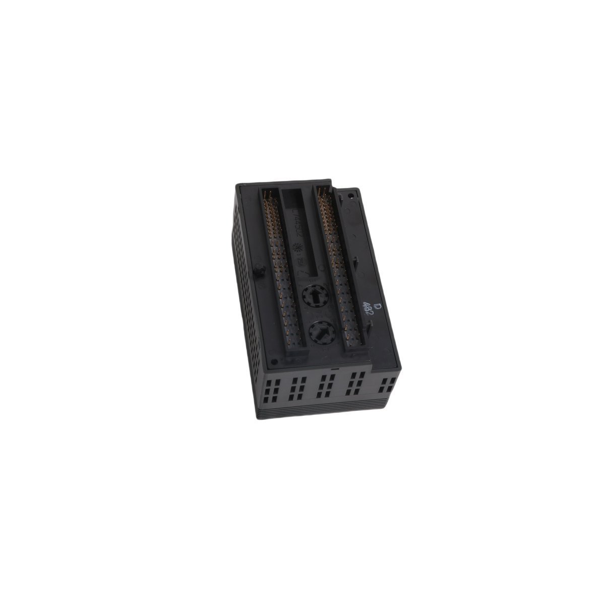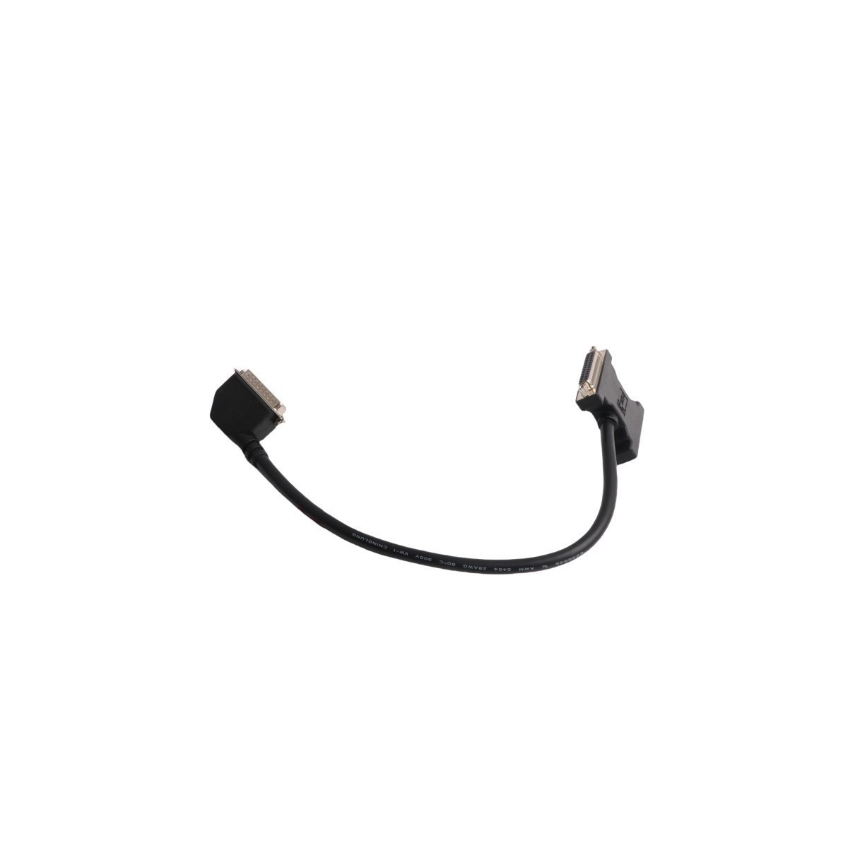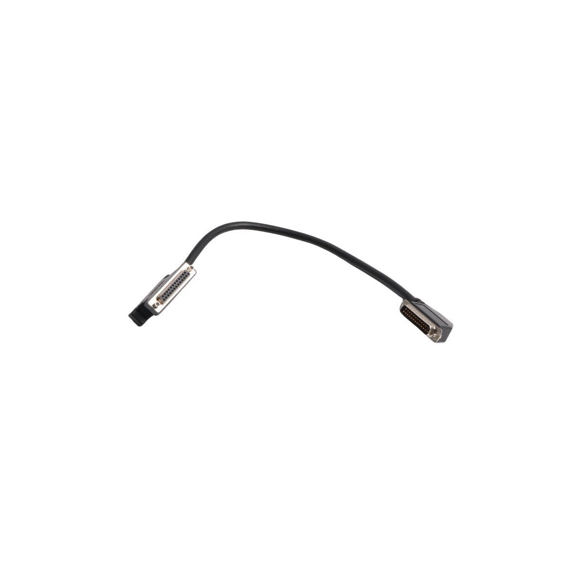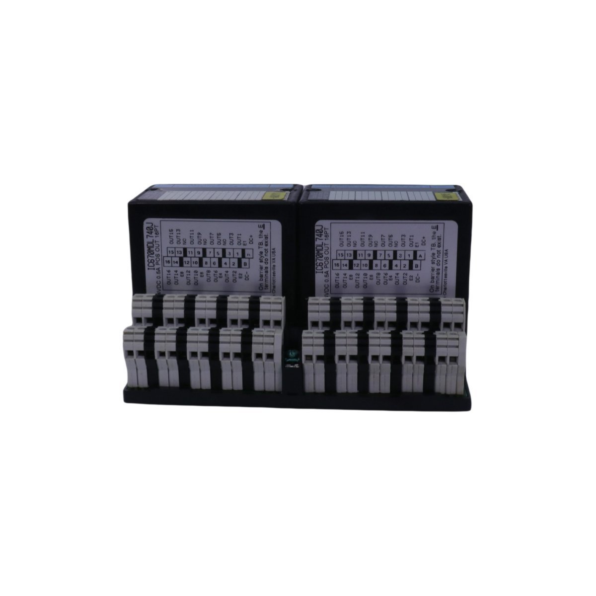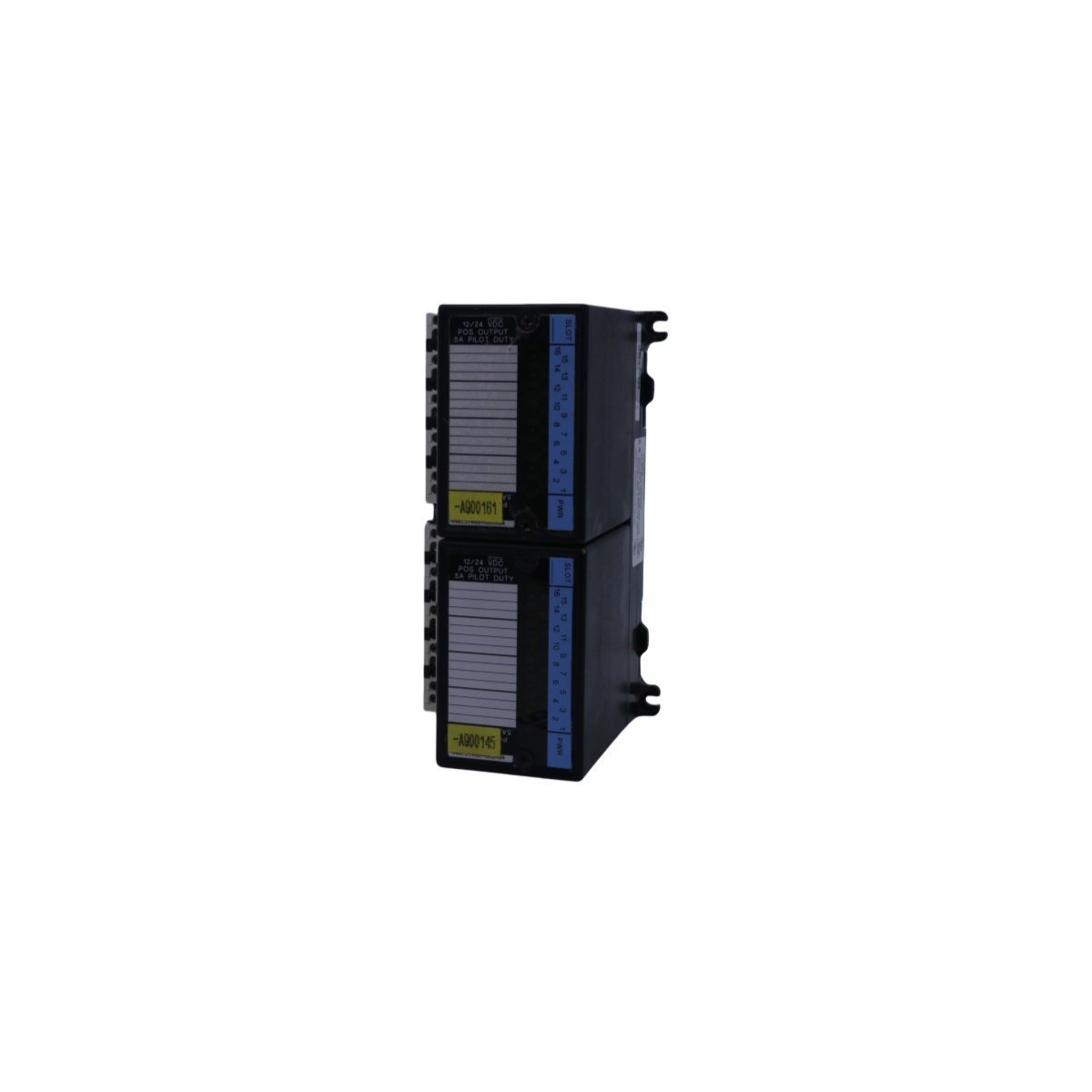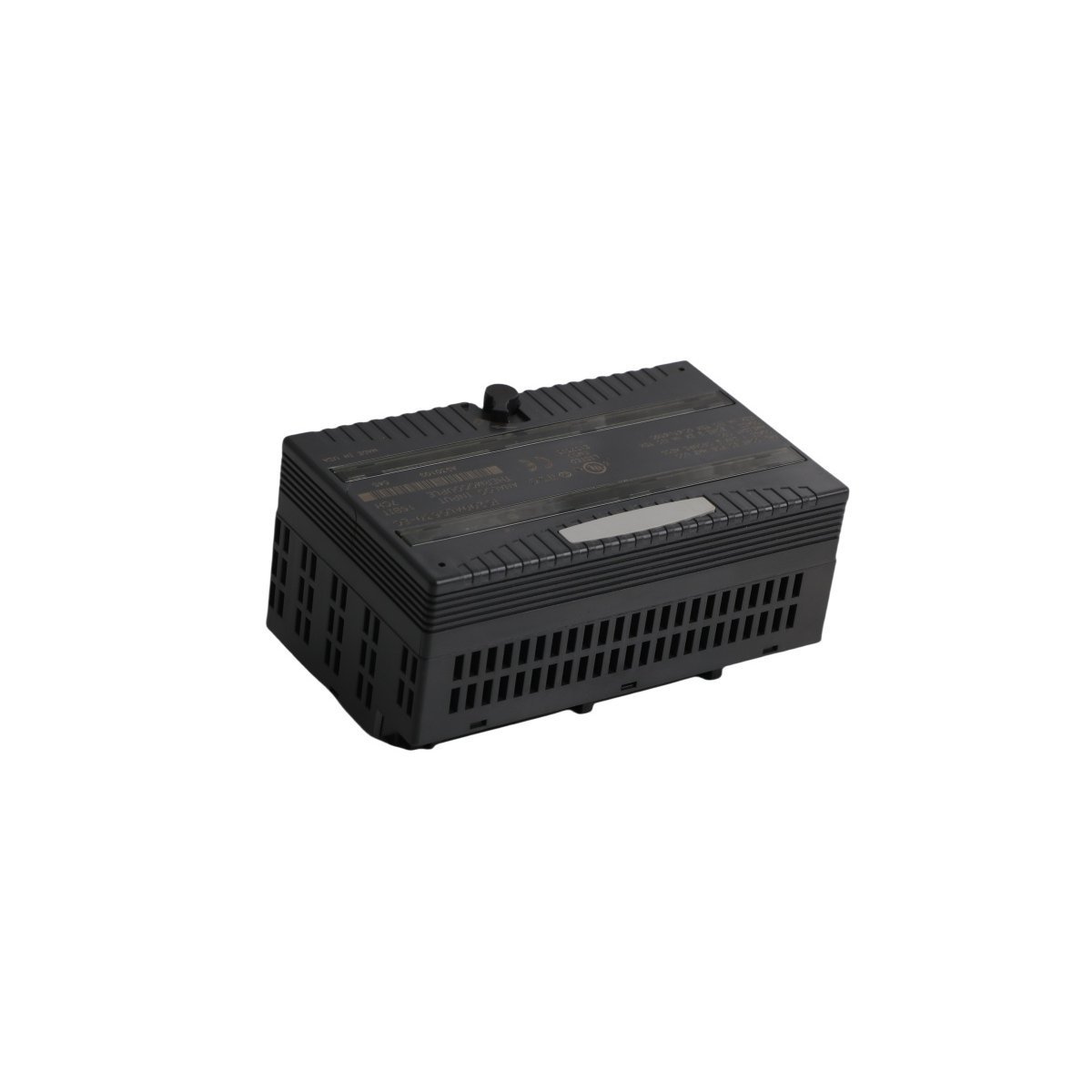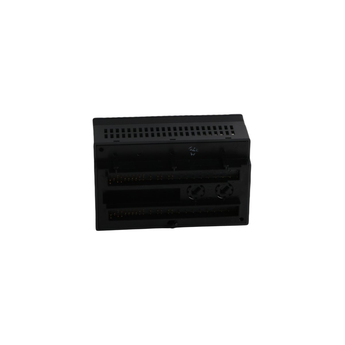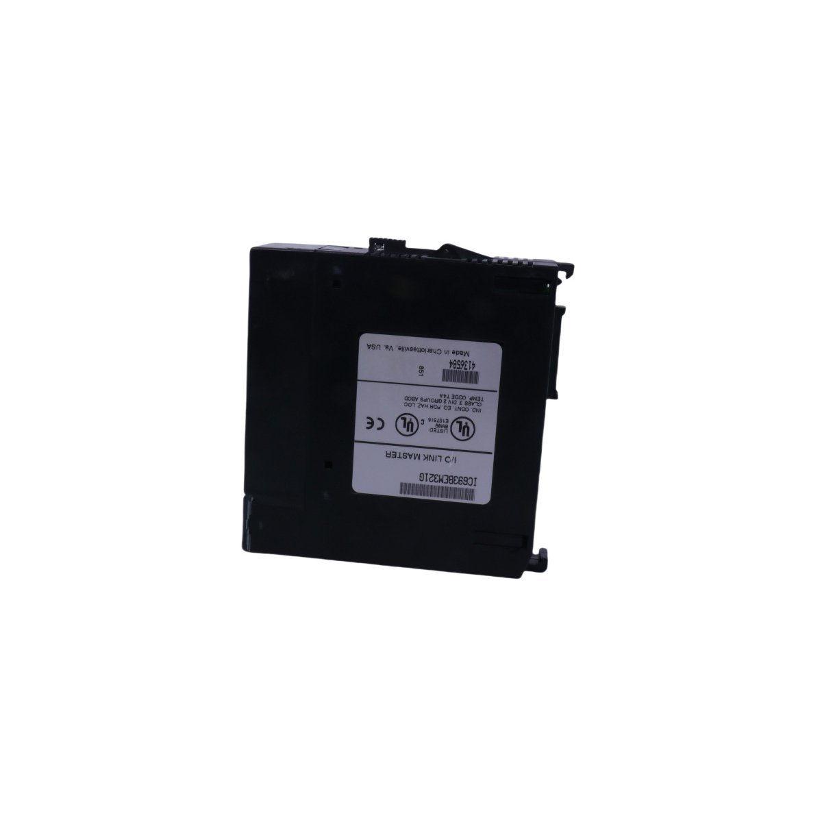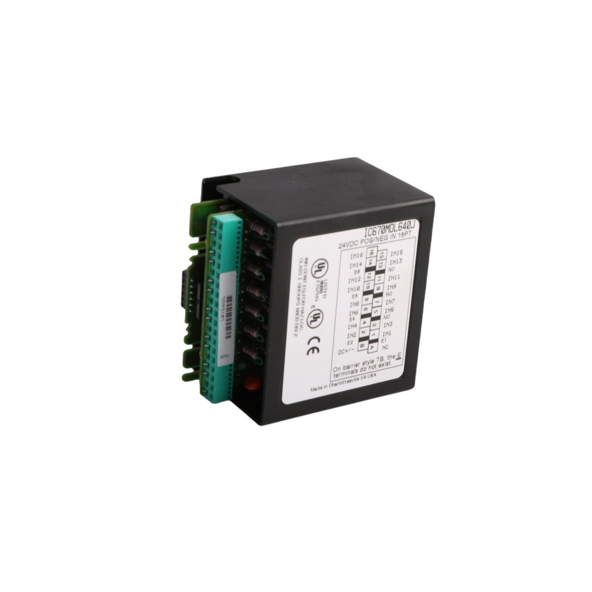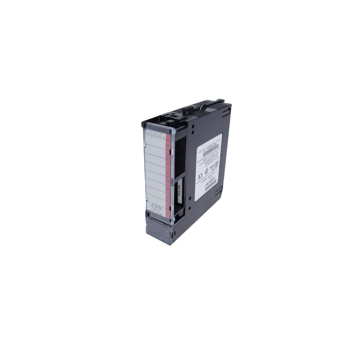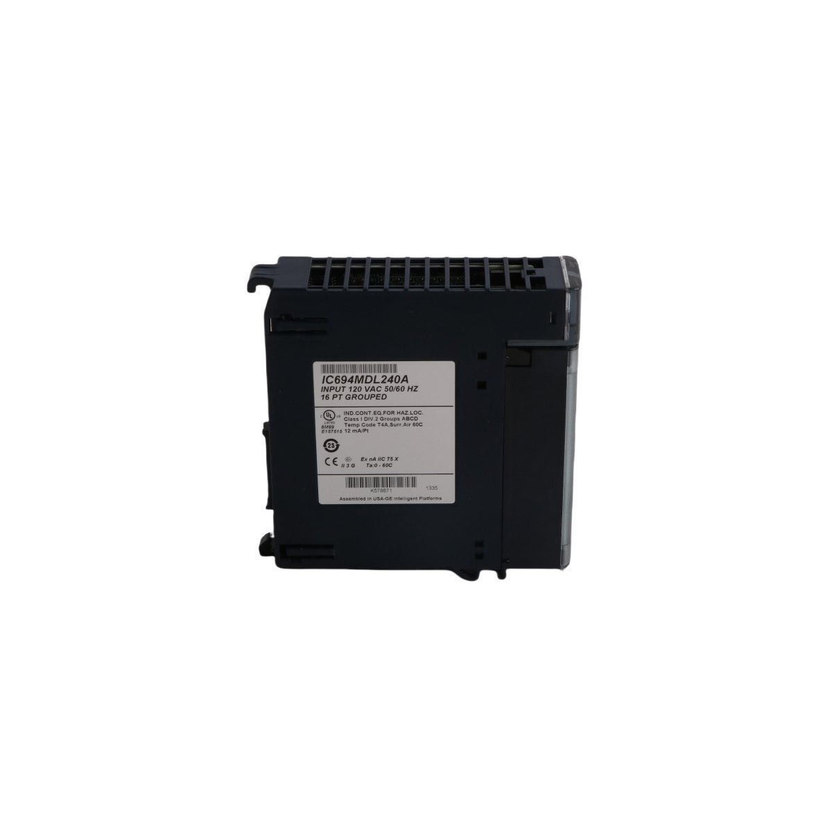
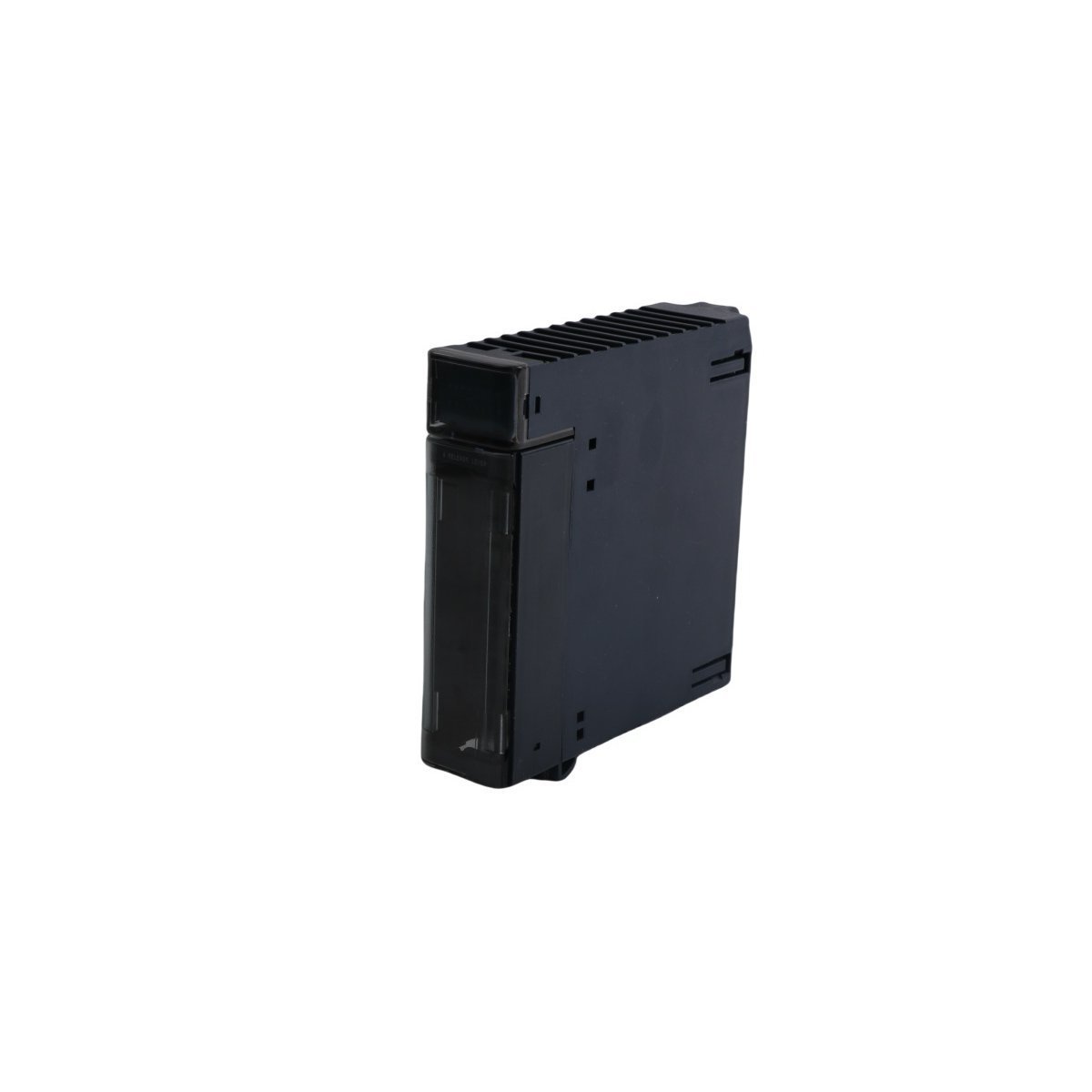
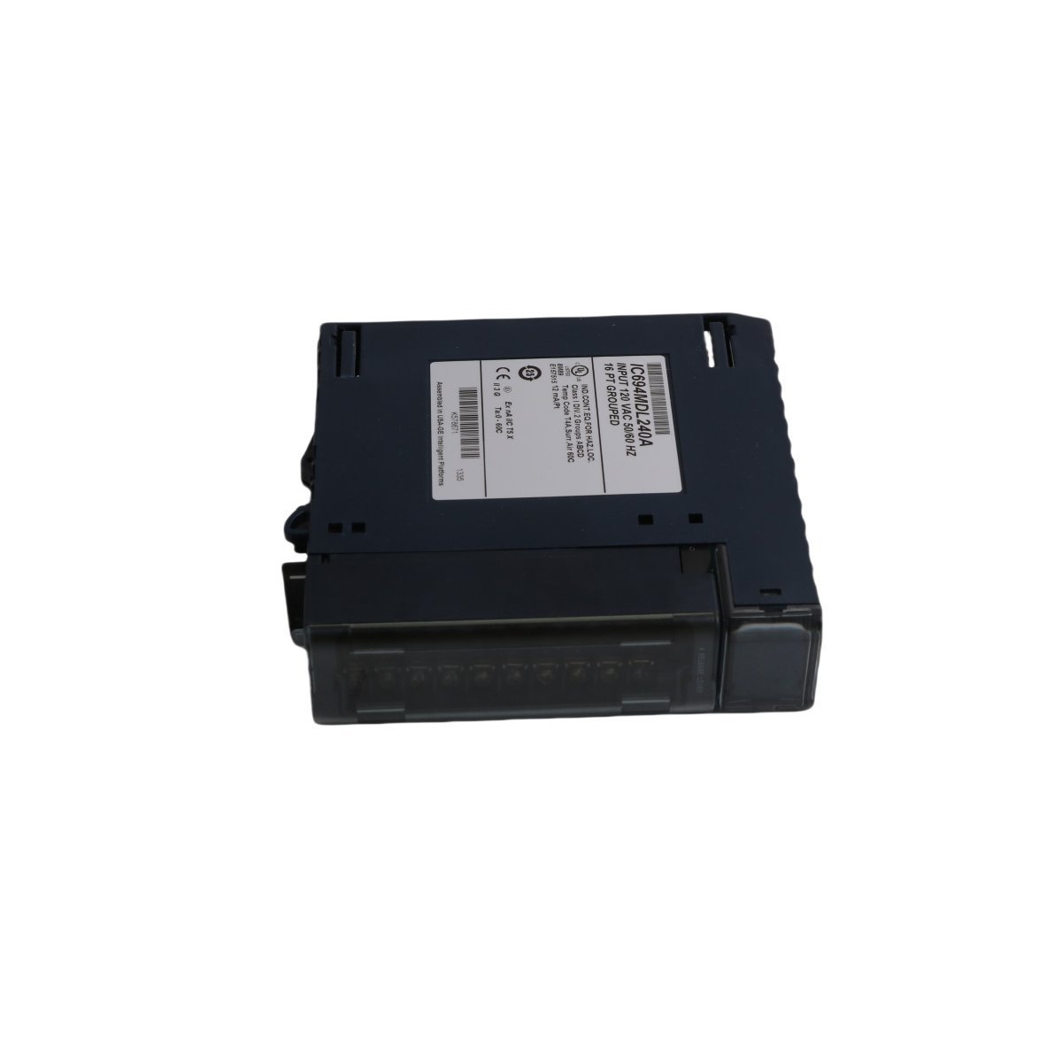
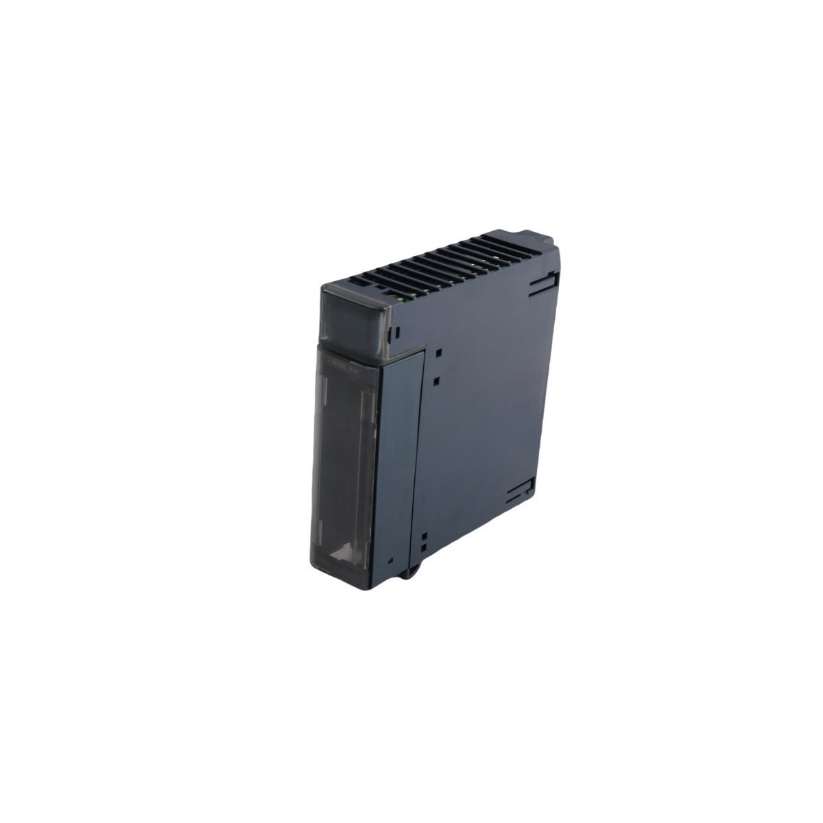
Configured for discrete AC signal acquisition in the PACSystems RX3i backplane architecture, the GE IC694MDL240 (IC694MDL240 Volt AC Input Module) provides direct electrical input monitoring of field-operated switching devices and AC-powered sensing circuits. The module supports 16 input channels for 120 VAC systems, accepts 85-132 VAC input signals at 50/60 Hz, and interfaces with the RX3i controller through a single-slot backplane connection.
Suffix Breakdown & Model Matrix
The available documentation identifies a single catalog number, IC694MDL240, without any documented suffix variants or ordering-code subdivisions. No suffix matrix is specified by the manufacturer data provided.
Hardware Specifications
Parameter
Specification
Model
IC694MDL240
Brand
GE
Product Series
PACSystems RX3i
Module Type
Volt AC Input Module
Input Channels
16 discrete inputs
Input Voltage Range
85-132 VAC
Nominal Input Voltage
120 VAC
Input Frequency
50/60 Hz
ON-State Voltage
74-132 VAC
OFF-State Voltage
0-20 VAC
ON Response Time
30 ms
OFF Response Time
45 ms
Backplane Current Consumption
90 mA
Isolation Rating
250 VAC continuous, 1500 VAC for 1 minute
Status Indication
Individual channel LEDs
Mounting
Single-slot RX3i backplane installation
Origin
USA
Weight
0.28 kg
Dimensions
3.5 x 13.2 x 13.5 cm
Operating Temp
Not specified in provided documentation
Power Consumption
Not specified in provided documentation
Compliance
UL 508
Environmental Classification
Class 1, Division 2 compatible applications
Backplane Communication and I/O Density Scaling
The IC694MDL240 occupies a single slot within the PACSystems RX3i I/O rack while providing 16 discrete AC input channels. This channel density enables consolidation of field contact signals including pushbuttons, limit switches, auxiliary contacts, and proximity switches. Data transfer between the module and the controller occurs through the RX3i backplane interface, eliminating separate communication wiring for individual input channels.
The module draws 90 mA from the backplane supply and can be installed in any compatible RX3i slot supported by available system I/O capacity. Channel status is reported through dedicated front-panel LEDs, allowing local verification of field signal presence during commissioning and troubleshooting.
Frequently Asked Questions
Q: Does the IC694MDL240 support hot insertion or hot removal?
A: The supplied documentation does not specify hot-swap capability. Module insertion and removal should follow the RX3i system maintenance procedures and applicable controller power-state requirements.
Q: What field devices can be connected to the input channels?
A: The module is intended for AC discrete input signals generated by devices such as push-button switches, limit switches, relay contacts, and AC-powered proximity sensors operating within the specified voltage range.
Q: What isolation protection is provided between field wiring and module electronics?
A: The module provides optical isolation rated at 250 VAC continuous voltage and 1500 VAC for a 1-minute test interval.
Field Installation Guidelines
Verify that the field signal voltage remains within the specified 85-132 VAC operating range before energizing the module.
Separate AC input wiring from high-current motor and drive conductors to reduce induced electrical noise.
Terminate cable shields according to the facility grounding standard and avoid multiple shield ground points unless required by the site design specification.
Confirm correct channel addressing and field terminal assignments before controller startup.
Inspect LED channel indicators during commissioning to verify correspondence between field device operation and controller input status.
Follow lockout and electrical safety procedures before connecting or disconnecting field wiring.
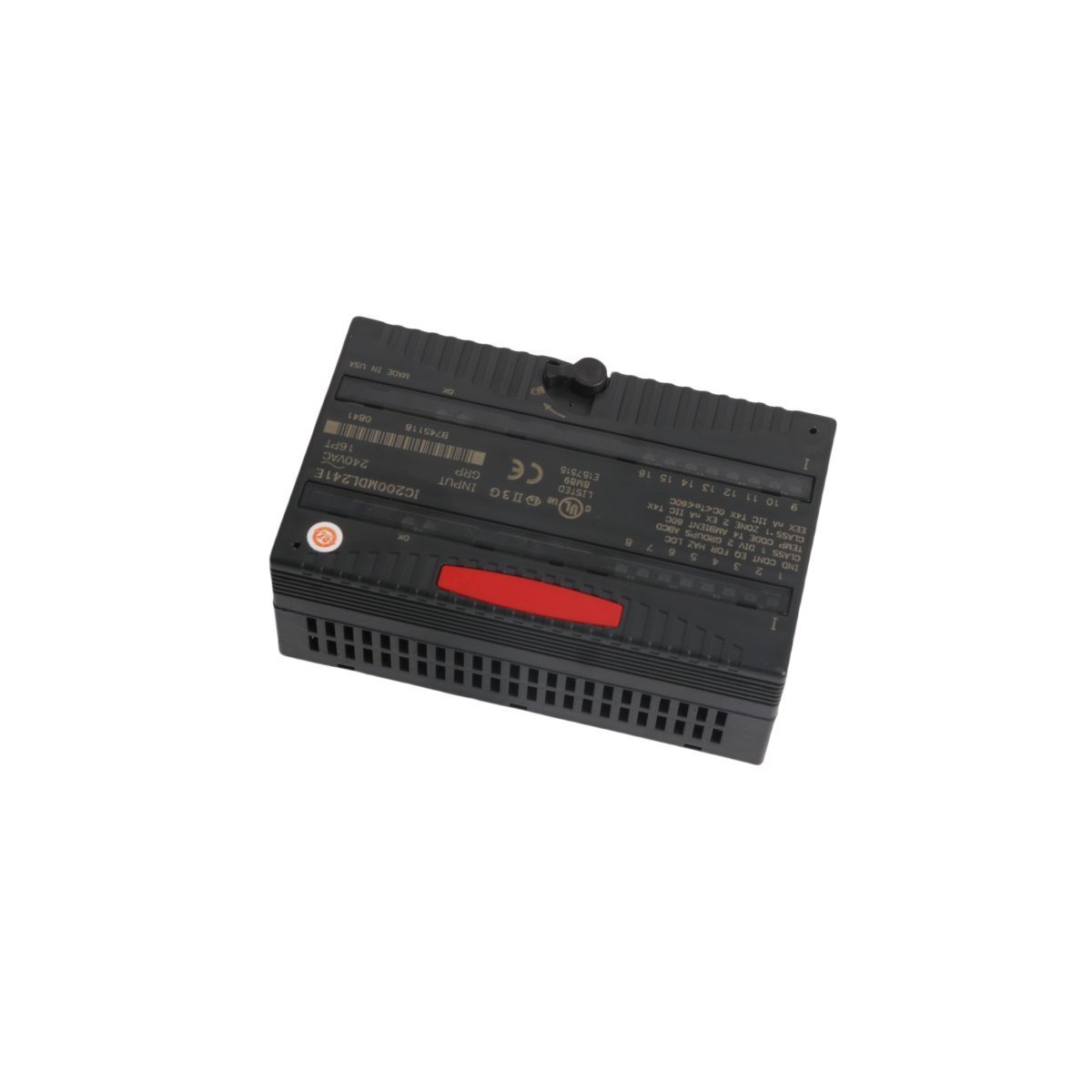
The GE IC200MDL241, also cataloged as the IC200MDL241 AC Input Module, operates as a dedicated hardware component for discrete signal acquisition within VersaMax I/O and control networks. Logic states from field-connected devices are processed through sixteen channels, and the resulting data is transmitted via the backplane to the host CPU. Input transitions are continuously monitored by integrated LED indicators, while electrical isolation is maintained across input groups to ensure signal integrity during operation.
Hardware Specifications
Parameter
Specification
Model
IC200MDL241
Brand
GE
Origin
USA
Weight
0.1 kg
Dimensions
11.0 cm x 5.8 cm x 6.5 cm
Operating Temp
Standard Industrial Range
Power Consumption
110.0 mA at 5.0 VDC (Backplane)
Nominal Voltage
240 VAC
Input Range
0 to 264 VAC
ON-state Voltage
155 VAC to 264 VAC
OFF-state Voltage
0 VAC to 40 VAC
PLC and Control Network Integration
System communication velocity and deterministic performance are regulated by the VersaMax backplane architecture. Backplane bus communication velocity is optimized to ensure low-latency data throughput for high-density I/O configurations. Furthermore, firmware flash compatibility is supported, allowing for field updates when the module is integrated into existing VersaMax PLC frameworks. To maintain operational stability, I/O density scaling is managed through the modular backplane, which facilitates the addition of supplemental discrete or analog modules without interrupting the host processor scan cycle.
Frequently Asked Questions
Q: Is the module capable of being hot-swapped while the backplane is energized?A: Yes, the module is designed to support hot-swapping. However, care must be taken to ensure that field wiring is disconnected or secured to prevent accidental shorting of the AC input terminals during extraction.Q: How is the group isolation managed across the sixteen channels?A: The sixteen inputs are organized into two groups of eight. While there is no point-to-point isolation, 1500 VAC of group isolation is provided for a duration of one minute to protect against common-mode electrical transients.
Field Installation Guidelines
The module is intended for mounting onto a DIN-rail supported I/O carrier. The module must be seated firmly until a physical click is confirmed.
Field wiring is connected via the integrated snap-in terminal blocks. Standard industrial torque specifications should be applied to prevent contact resistance.
AC input leads must be routed away from low-voltage communication cables to mitigate electromagnetic interference.
Status LEDs should be verified for correct illumination cycles upon the application of field power. If an LED fails to trigger during a signal state change, the input wiring and voltage levels must be measured against the technical specifications.
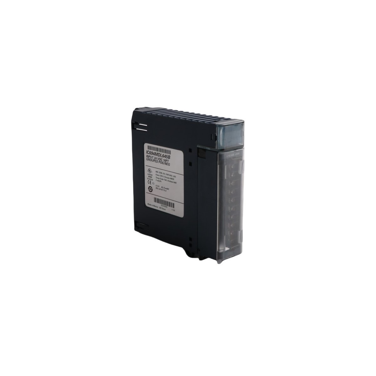
The GE IC694MDL645, also cataloged as the IC694MDL645 Digital Input Module, operates as a dedicated hardware component for signal acquisition within PACSystems RX3i control networks. Incoming field signals are processed through sixteen discrete channels, and the resulting state data is transmitted to the backplane. Electrical compatibility with both positive and negative logic configurations is maintained, and operational states are continuously monitored via integrated LED indicators.
Hardware Specifications
Parameter
Specification
Model
IC694MDL645
Brand
GE
Origin
USA
Weight
0.3 kg
Dimensions
3.5 cm x 13.2 cm x 13.5 cm
Operating Temp
Standard Industrial Range
Power Consumption
Backplane Dependent
Input Channels
16
Rated Voltage
24 VDC
ON-state Voltage
11.5 VDC to 30 VDC
OFF-state Voltage
0 VDC to 5 VDC
Response Time
7 ms (typical)
PLC and Control Network Integration
System communication velocity and deterministic performance are regulated by the PACSystems backplane architecture. Signal integrity is preserved through high-level galvanic isolation, rated at 1500 VAC for one minute, whereby electrical noise interference is mitigated. Furthermore, firmware flash compatibility is ensured during module replacement, provided that the backplane remains energized within the specified voltage tolerances. The module is engineered for integration within both local and remote RX3i I/O racks, while support for RX7i systems is provided exclusively in distributed I/O configurations.
Frequently Asked Questions
Q: Is the module capable of being hot-swapped while the system is powered?A: Yes, the module is designed to be extracted and inserted while the RX3i backplane is energized; however, field wiring must be verified to ensure no short-circuit conditions are created during the removal process.Q: How is the signal response time managed in high-speed applications?A: A typical response time of 7 milliseconds is imposed by the hardware filter circuits. This latency is inherent and should be accounted for when high-speed pulse capture is required.
Field Installation Guidelines
The module is to be mounted onto the designated RX3i backplane slot. A mechanical click is heard when the module is fully seated.
Prior to wiring, the 24 VDC power supply must be verified for voltage stability.
Signal wires are to be connected to the terminal block. A secure, firm connection is required to prevent intermittent signal loss caused by vibration.
Shielding must be grounded at the designated earth terminal to ensure that electromagnetic interference is properly diverted.
Once the module is seated and wired, the status LEDs are to be inspected for illumination corresponding to active field device states.
The GE IC693CBL305, also cataloged as the IC693CBL305 Wye connection cable, operates as a dedicated hardware component for serial port signal splitting within Series 90-30 PLC networks. The cable provides direct physical execution of port separation, routing dual channel data paths from a high-density host connector into two distinct 25-pin interfaces. By isolating Port 1 and Port 2 signals at the physical layer, the component facilitates structured cable management and electrical signal routing for communication coprocessor modules.
Hardware Specifications
Parameter
Specification
Model
IC693CBL305
Brand
GE
Origin
USA
Weight
0.14 kg
Dimensions
45.0 cm x 6.2 cm x 1.6 cm
Operating Temp
Standard Industrial Range
Power Consumption
Passive (No active components)
Cable Length
30.5 cm (1 foot)
Interface Type
RS-232 / RS-485
PLC and Control Network Integration
Backplane bus communication velocity and deterministic synchronization for the Series 90-30 system are facilitated through the effective routing of serial data. Firmware flash compatibility within the host modules is supported, ensuring that the physical signal path provided by the IC693CBL305 maintains high integrity across logic execution cycles. Furthermore, I/O density scaling and port configuration are optimized via this hardware split, enabling the PLC to process communication packets without signal cross-talk. When utilized in complex automation architectures, the cable acts as a protocol bridge, ensuring that RS-232 and RS-485 signals are routed to their appropriate logical destinations on the coprocessor.
Frequently Asked Questions
Q: Does the IC693CBL305 cable support active signal buffering or protocol conversion?A: No. The IC693CBL305 is a passive wiring accessory designed specifically for physical port splitting. It does not contain active electronic components for signal amplification or protocol translation.Q: Can the cable be used to connect different electrical standards on Port 1 and Port 2 simultaneously?A: The cable is configured to route signals from the combined host connector to the designated 25-pin outputs. While Port 1 supports RS-232 and Port 2 supports RS-232 or RS-485, the limitation is defined by the host coprocessor module's internal configuration, not the cable itself.
Field Installation Guidelines
Inspect the connectors for bent pins before insertion into the CMM or PCM module ports.
The right-angle connector must be fully seated into the host module port to ensure consistent electrical contact.
Ensure the dual 25-pin connectors are properly identified and labeled as Port 1 and Port 2 during installation to avoid configuration errors.
Secure the cable using standard cable ties to prevent mechanical strain on the host module ports, as excessive tension can lead to intermittent signal loss in industrial environments.
The GE Fanuc IC693CHS398 is a 5-slot expansion baseplate for Series 90-30 PLC systems. It enables seamless I/O expansion up to 50 feet from the CPU, featuring a dedicated power supply slot and a 25-pin D-type connector for high-speed data transmission.
The GE Fanuc IC200CHS022 is a 36-terminal, box-style I/O carrier for the VersaMax series. It supports high-density field wiring, DIN-rail mounting, and tool-free module replacement to maximize system uptime and reliability.
The GE Fanuc IC670CHS002 is a high-performance terminal block for Field Control systems. It features isolated common groups (A, B, and E) for flexible power distribution and a modular design that allows for I/O module replacement without disconnecting field wiring.
The GE Fanuc IC693ALG391 is a 2-channel analog output module for Series 90-30 PLCs. It provides high-resolution 4-20 mA and 0-10 V signals with isolated 24 VDC power support. This precise module ensures reliable control for valves, drives, and other industrial actuators.
The GE Fanuc IC693CPU351 is a high-performance 25 MHz CPU for Series 90-30 PLCs.It features 240KB user memory, three serial ports, and supports up to 2048 I/O points, providing robust control for complex industrial automation and DCS applications.
The GE Fanuc IC200ALG240 provides eight isolated analog input channels with 16-bit resolution for the VersaMax series. It supports both voltage and current signals while offering 1500 VAC isolation and advanced diagnostics to ensure maximum signal integrity in complex industrial environments.
The GE Fanuc IC220PWR013 is a VersaPoint fused segment terminal designed to create protected sub-circuits within a PLC system. It features integrated fuse protection, real-time voltage diagnostics, and status LEDs for enhanced industrial safety and monitoring
The GE Fanuc IC200ALG322 is a 4-channel analog voltage output module for the VersaMax PLC series. It provides ±10.24V outputs with 12-bit resolution, built-in field power diagnostics, and a compact design for precise industrial control applications.
The General Electric IC670MDL640 is a 16-point discrete output module designed for the Field Control I/O system. Operating at 24 Vdc, this module delivers high-speed, short-circuit protected switching for industrial solenoids, starters, and indicators in demanding automated environments.
We are committed to protecting your privacy. The information collected here is strictly used to provide the requested quotes, technical support, and relevant industrial automation solutions.