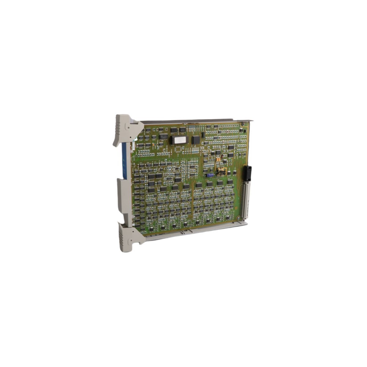
Honeywell MC-TDOR12 51309148-175 Digital Relay Output Board
Sale!
SKU: MC-TDOR12 51309148-175
Honeywell MC-TDOR12 51309148-175 Digital Relay Output Board
Genuine Honeywell MC-TDOR12 51309148-175 Digital Relay Output Board for MU-T Series DCS architectures. brand new surplus, global shipping available. Complete datasheet and installation guidelines.
The Honeywell MC-TDOR12, also cataloged as part number 51309148-175, functions as a high-density Digital Relay Output Board utilized within Honeywell MU-T Series architectures. Operating as a component of the Process Manager I/O subsystem in Honeywell Distributed Control Systems (DCS), this board converts low-level logical control signals into isolated contact outputs. This execution allows the safety and process loops to directly toggle high-current field elements such as motor starters, interposing relays, solenoids, and indicators without back-feeding transient noise into the control processor.
Hardware Specifications
Parameter
Specification
Model
MC-TDOR12
Part Number
51309148-175
Brand
Honeywell
Origin
USA
Weight
0.72 kg
Dimensions
12 x 5.2 x 30.7 cm
Operating Temp
-40 to +85 deg C
Module Type
Digital Relay Output Board
System
MU-T Series / DCS
Communication Service
Backplane integration with serial/Modbus telemetry interface
Process Control & Channel-to-Channel Isolation
The Honeywell MC-TDOR12 features multiple mechanical or solid-state relay channels engineered to manage external load switching. To safeguard the upstream processing nodes from voltage variations or short circuits in the field, the board utilizes dedicated channel-to-channel isolation networks. This configuration maintains robust electrical boundaries between individual loops and the shared logic backplane, preventing fault propagation across critical 4-20 mA HART loop protocol lines, discrete inputs, and neighboring digital modules.
Frequently Asked Questions
Q: Does this relay output board require a separate field termination assembly (FTA)?
A: Yes. The MC-TDOR12 digital output board interfaces directly via a dedicated multi-conductor I/O cable to a corresponding Field Termination Assembly where field wiring is landed and fused.
Q: Can an individual relay channel be forced via system software for troubleshooting?
A: Yes. Control engineers can toggle individual relay output registers using software force commands within the DCS engineering environment to test contact loop state transitions.
Q: What happens to the relay contact positions if communication with the controller is lost?
A: The board relies on pre-configured fail-safe parameters. Depending on the system setup, the contacts will either hold their last state or drop out to a safe, de-energized condition.
Field Installation Guidelines
Electrostatic Discharge Warning: Ensure a proper connection to an ESD-grounded point before removing the module from its static-shielding packaging to protect the onboard logic registers.
Firmware Keying Alignment: Verify that the physical guide keys on the chassis slot match the orientation slots on the board before sliding it into the card file to avoid connector pin damage.
Retention Fasteners Engagement: Once seated securely into the backplane, tighten all integrated module retaining screws to establish frame ground continuity and prevent vibration displacement.
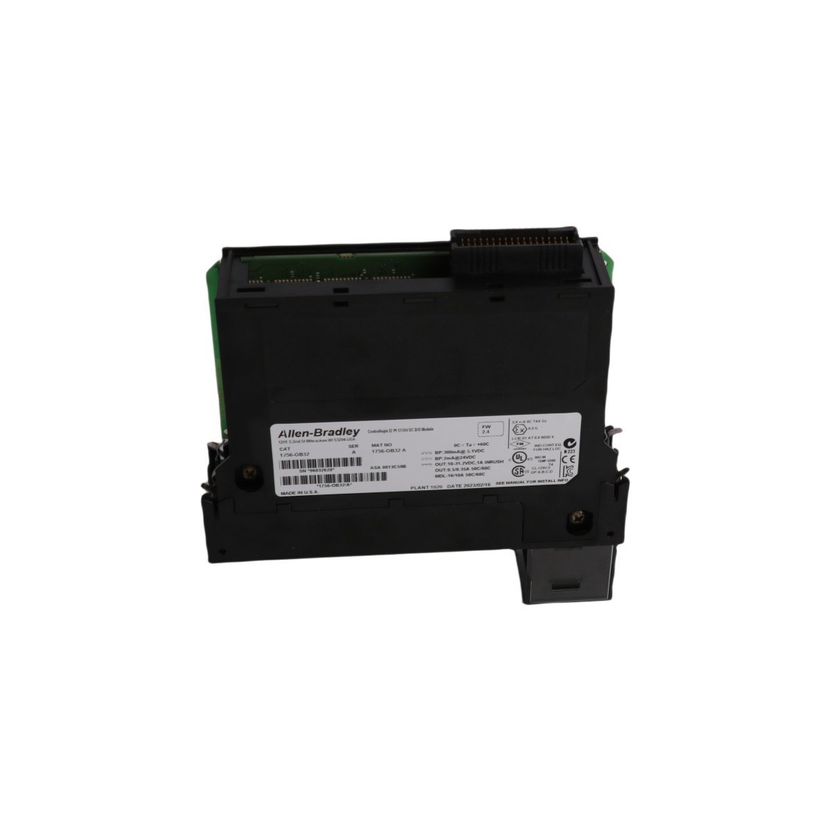
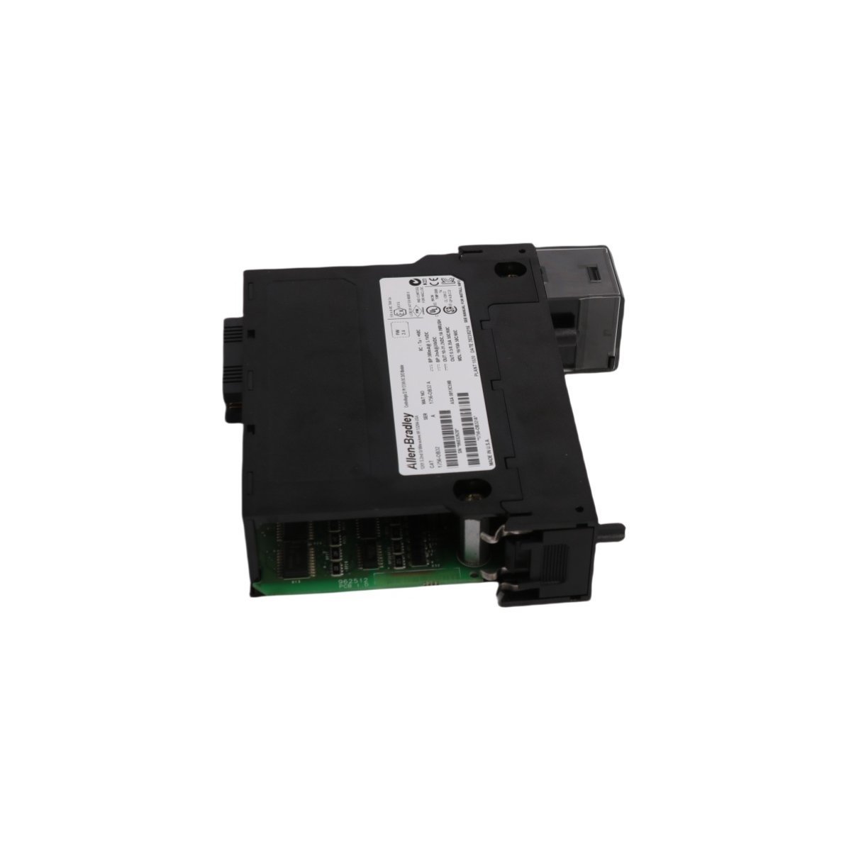
Purchase the Allen-Bradley 1756-OB32 ControlLogix Digital Output Module with 32 points and electronic fusing. Brand New, Original Stock with Global Shipping. Secure this authentic industrial automation spare now.
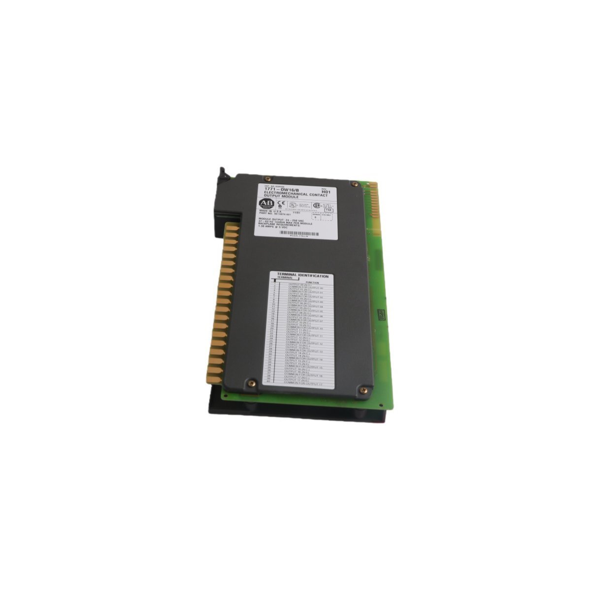
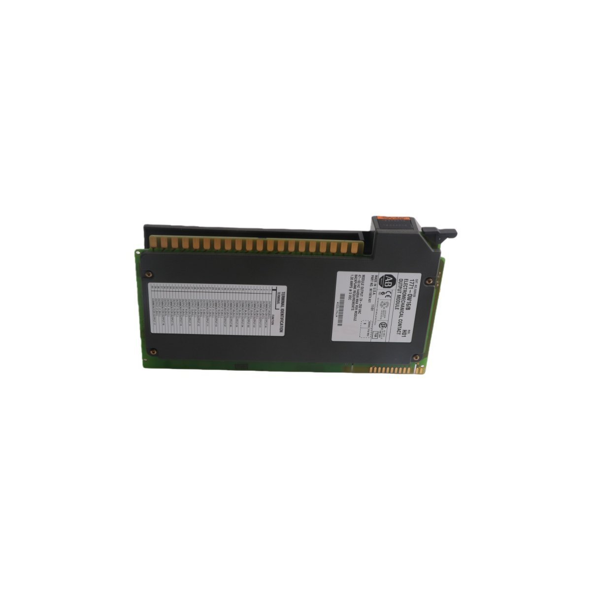
The Allen-Bradley 1771-OW is an 8-channel electromechanical relay output module engineered for the classic PLC-5 architecture. Procure this factory-original surplus hardware in brand new condition, backed by global logistics support and rapid transit options. Contact us now to secure your technical components.
The Allen-Bradley 1756-OV16E is a 16-point current-sinking digital output module for the ControlLogix platform operating between 10 and 30V DC. This single-slot module features advanced onboard electronic fusing to protect circuits against overcurrent, delivers 1A per channel maximum current, and provides diagnostic feedback directly to the controller.
The Allen-Bradley 1756-OA16 is a 16-point discrete AC output module for ControlLogix systems. It provides reliable 74-265V AC switching with integrated diagnostics, 0.5A per point capacity, and robust thermal performance for industrial automation.
The Allen-Bradley 1756-OA16I is a 16-point isolated AC digital output module for ControlLogix systems. It supports 75-265 VAC operation and 2A per point current capacity. This reliable 120/240V module provides per-channel isolation for demanding industrial control applications.
The Allen-Bradley 1771-OA is an 8-channel AC output module for PLC-5 systems. It supports 92-138V AC loads with a 1.5A continuous current per point. This module includes built-in fuse protection and status indicators for reliable industrial automation and device control.
The Allen-Bradley 1756-OA8D is an 8-point diagnostic AC output module for ControlLogix systems. It features 74-132V AC operation, 1A current per point, and electronic fusing. Integrated diagnostics identify no-load and short-circuit faults to maximize system uptime.
The Allen-Bradley 1756-OB16IS is a 16-point isolated digital output module for ControlLogix systems. Operating at 10-30V DC with a 2A per point rating, it features 8 scheduled outputs and individual channel isolation to ensure precise, high-speed switching and maximum electrical protection in PLC architectures.
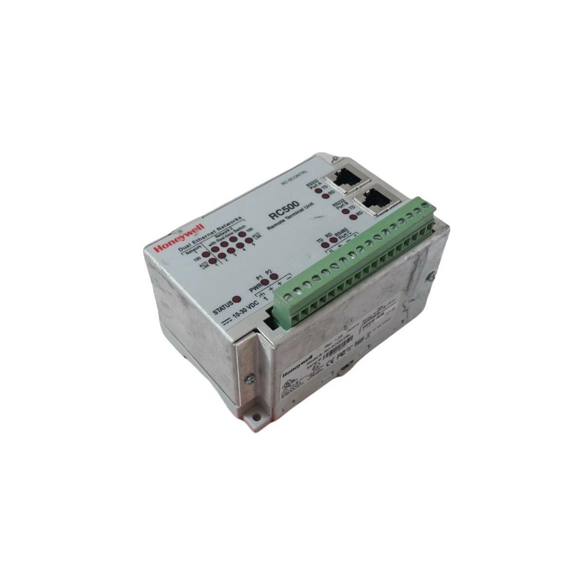
The Honeywell RC500 RTU (RC-SCONTRL) provides scalable, modular control for remote industrial assets. Featuring embedded Linux and DNP3/Modbus support, it delivers high-reliability automation for SCADA and Experion systems.
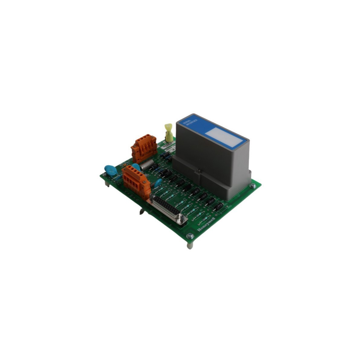
The Honeywell MC-TSIM12 (51303932-476) is a high-reliability serial interface module designed to bridge Honeywell controllers with Modbus devices. It provides efficient data translation and robust electrical isolation for seamless third-party equipment integration.
The Honeywell MU-PAOX03 (51304672-100) is a high-precision 4–20 mA analog output module designed for TDC 3000 and Experion PKS systems. It provides reliable control of field actuators with integrated diagnostics and support for redundant configurations.
The Honeywell MC-PLAM02 (51304362-150) is a high-precision Low Level Analog Input Processor for TDC 3000 systems. Designed for thermocouples and RTDs, it features integrated cold junction compensation and signal isolation to ensure accurate and reliable temperature monitoring in demanding industrial applications.
We are committed to protecting your privacy. The information collected here is strictly used to provide the requested quotes, technical support, and relevant industrial automation solutions.