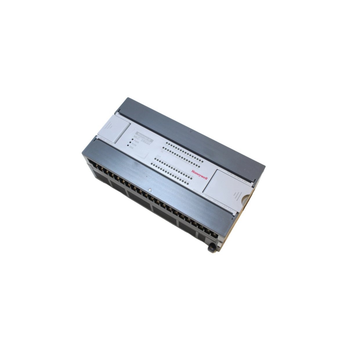
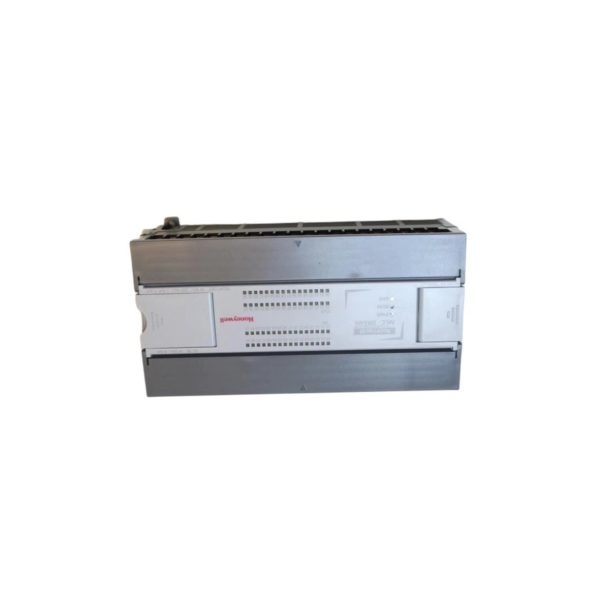
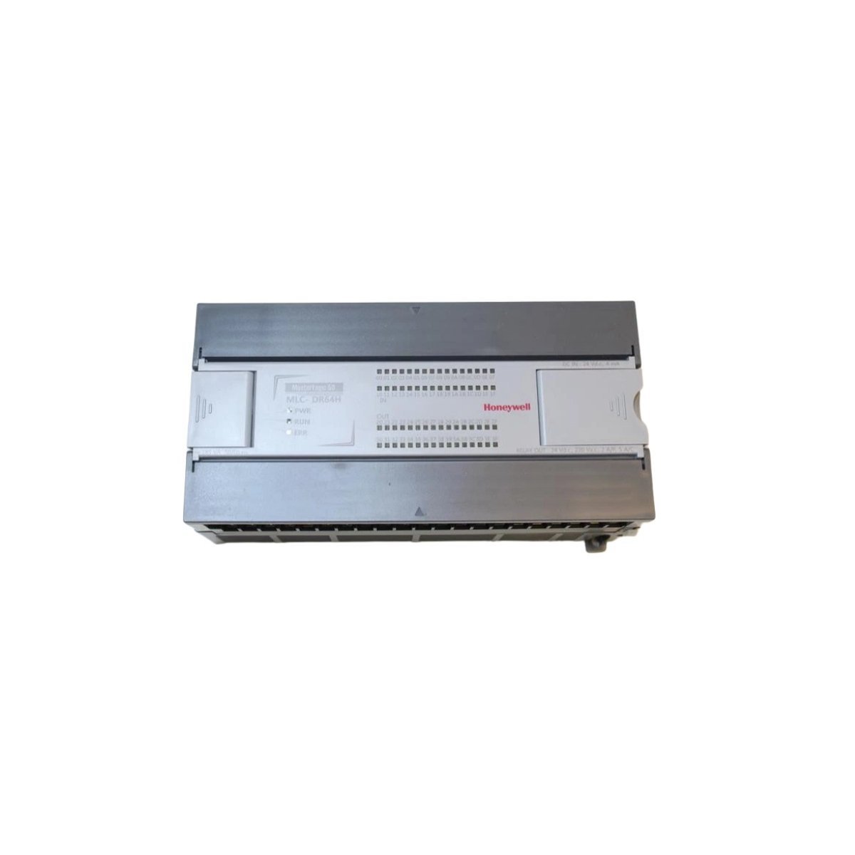
HONEYWELL MLC-DN64H/DC Digital Output Power Supply Module
Sale!
SKU: MLC-DN64H/DC
HONEYWELL MLC-DN64H/DC Digital Output Power Supply Module
Buy a genuine HONEYWELL MLC-DN64H/DC Power Supply Module featuring an integrated 32-point 24V DC sinking digital output array. Brand new unit with verified stock status. Expedited international shipping options available.
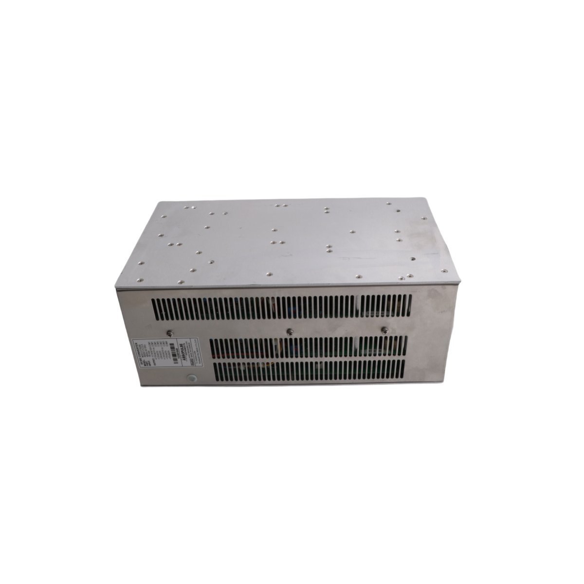
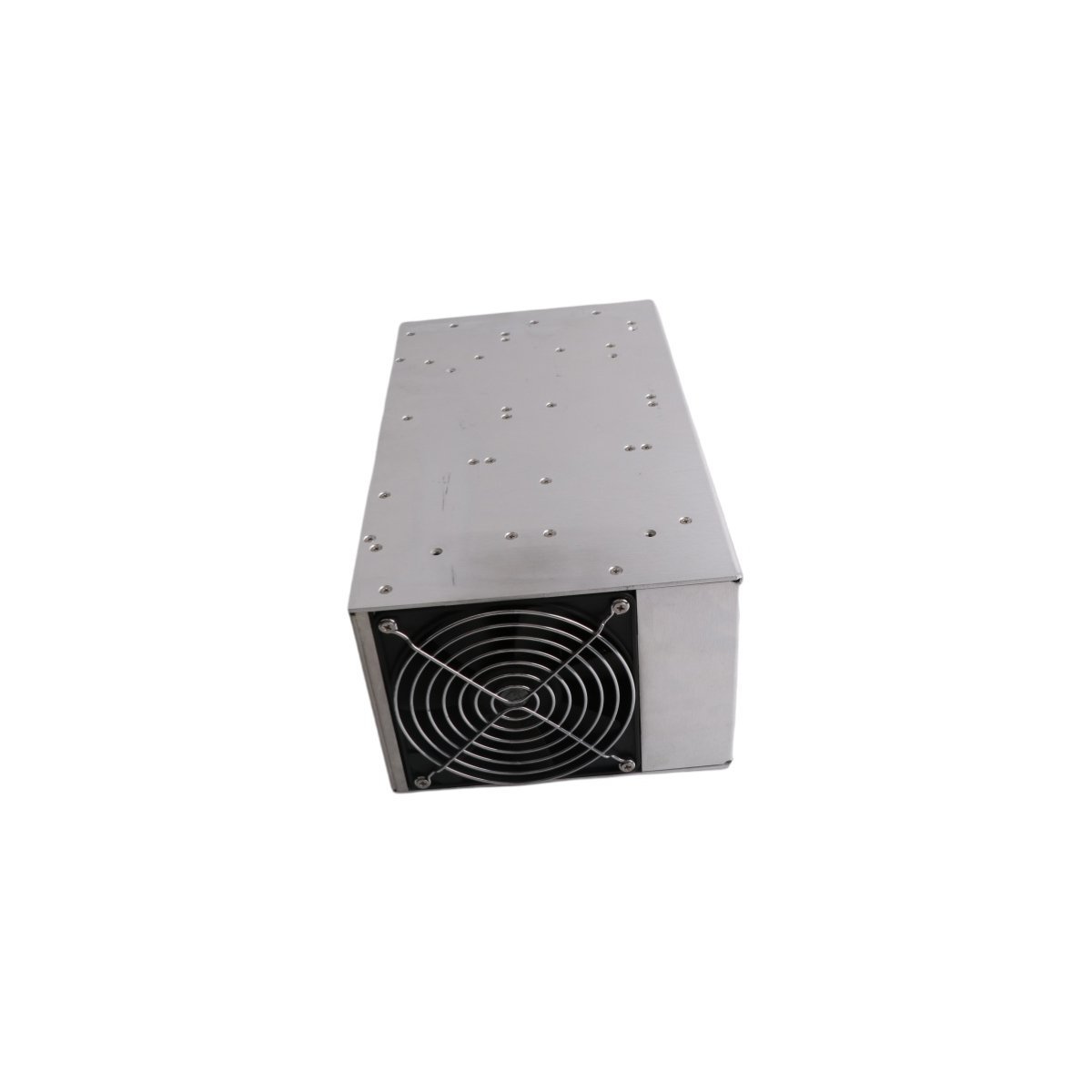
The HONEYWELL MLC-DN64H/DC is a high-performance combined Digital Output Power Supply Module engineered for MasterLogic PLC and DCS architectures. This versatile component delivers localized internal module power conversion while simultaneously operating a high-density, high-speed digital output interface designed to control field devices with precise determinism.
Hardware Specifications
Parameter
Specification
Model Number
MLC-DN64H/DC
Manufacturer
HONEYWELL
Module Type
Digital Output Power Supply Module
Origin
USA
Weight
0.4 kg (Net card weight) / 1.4 kg (Gross assembly weight)
Dimensions
7 x 14 x 14.5 cm
Output Capacity
32-point sinking outputs
Rated Load Voltage
24 VDC (Operational range: 10.2 to 26.4 VDC)
Max Load Current
0.5A per point
Execution Speed
83 nanoseconds per step (Basic instructions)
Electrical Isolation
Photo-coupler insulation
Input Supply Voltage
100-240 VAC
Surge Protection
Built-in Zener diode clamping networks
Off Leakage Current
0.1 mA
On Voltage Drop
0.4 VDC
Process Control & DCS Integration
The MLC-DN64H/DC bridges power distribution and discrete sequence execution within a single physical footprint. It handles 32 high-current sinking outputs, using photo-coupler isolation barriers to protect sensitive backplane microprocessors from field-side electrical transients or inductive feedback loops.
The module supports diverse scanning topologies to optimize control loops based on application urgency:
Repetitive Scan & Cyclic Scan: Standard sequential execution profiles for basic logic loops.
Its internal processing core runs at an ultra-fast speed of 83 nanoseconds per basic instruction step. It natively supports a command matrix containing 28 basic and 687 applied instructions configured via Ladder Diagram (LD) and Instruction List (IL) programming languages.
Frequently Asked Questions
Q: How does a sinking digital output loop behave electrically on this module?
A: In a sinking configuration, the module’s internal solid-state switch connects the field device load to the negative return path (DC Common). The external 24 VDC supply must be fed directly to the load terminal first.
Q: Is this module capable of driving heavy inductive loads like large solenoid valves?
A: Yes. Each point supports up to 0.5A and features integrated Zener diode surge suppression. However, for highly repetitive inductive switching or loads near the 0.5A threshold, installing an external flyback diode across the load is highly recommended to minimize localized heat generation.
Q: Can this power supply drive external field transmitters?
A: No. The primary 100-240 VAC supply input powers the module’s internal logic and backplane rail architecture. Field devices driven by the 32 digital output channels must be energized using a separate, external 24 VDC power loop.
Field Installation Guidelines
Confirm that the main rack AC source breaker is switched off before mounting or extracting the module.
Align the card layout tabs with the designated slot guide rails and push firmly until the backplane multi-pin bridge clips lock into place.
Wire the 100-240 VAC line, neutral, and physical earth ground to the dedicated power terminals, verifying correct ground continuity to the chassis.
Route field digital output wires separately from high-voltage motor starters to preserve low electrical noise thresholds.
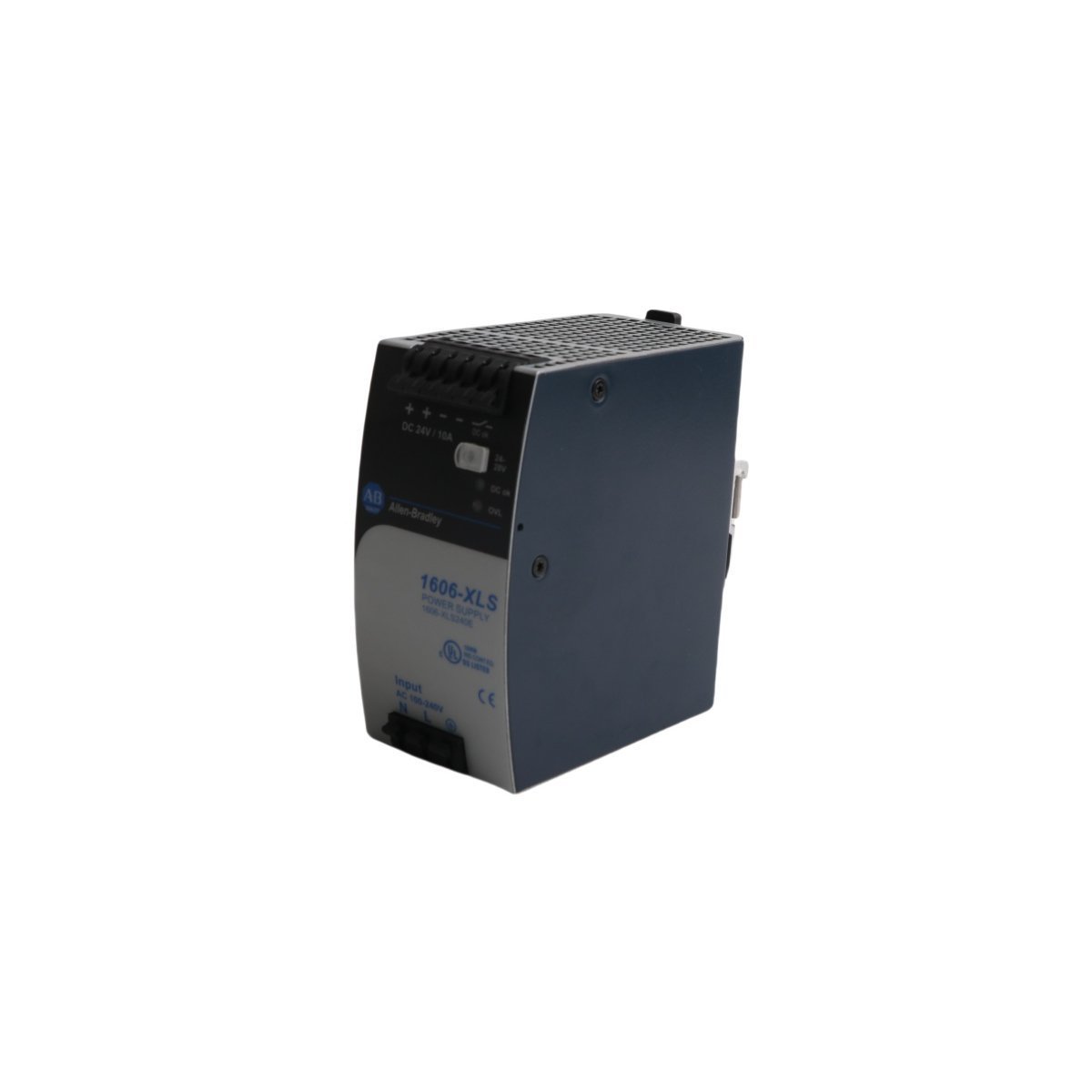
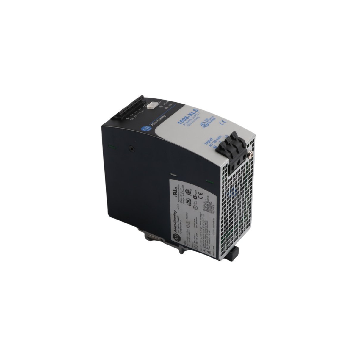
The Allen Bradley 1606-XLS240E, also cataloged as the 1606-XLS240E Performance Power Supply, operates as a dedicated hardware component for power conversion and voltage regulation within industrial control networks.
Hardware Specifications
Parameter
Specification
Model
1606-XLS240E
Brand
Allen Bradley
Origin
USA
Weight
0.9 kg
Dimensions
6 x 12.3 x 13 cm
Operating Temp
-25 deg C to 70 deg C
Power Consumption
240 W output rating
Profinet and EtherNet/IP Deterministic Networks
The power supply unit maintains stable backplane bus communication velocity and supports firmware flash compatibility across integrated automation nodes. Operating within deterministic network environments, the module delivers consistent DC voltage distribution while managing transient loads. High-speed switching topologies and low EMI emissions ensure that control data streams across connected Profinet and EtherNet/IP architectures remain uncorrupted by electrical noise.
Frequently Asked Questions
Q: What are the input voltage tolerances for this power supply model?A: The unit accepts standard industrial AC input ranges and incorporates built-in surge voltage protection limits to safeguard internal rectification circuits against grid anomalies.Q: How is thermal dissipation handled during maximum continuous load operations?A: Thermal management relies on natural convection cooling, requiring adequate vertical clearance above and below the housing to maintain specified operating temperature profiles without forced airflow.
Field Installation Guidelines
Mount the unit securely onto a standard DIN-rail inside the control cabinet, ensuring sufficient clearance for convection cooling airflow. Connect incoming AC mains and protective earth conductors to the designated terminals in accordance with local electrical safety codes. Verify output voltage at the screw terminals using a calibrated multimeter before connecting downstream PLC loads.
The Allen-Bradley 80026-173-23-R is a reliable DC/DC power supply module designed for PowerFlex 700 drives, featuring conformal coating for harsh environments.
The Emerson 1X00024H01 WH1-2FF is a high-reliability power supply module for DeltaV SIS and Ovation systems. It provides 0.9kg of robust hardware for critical safety process control.
The GE 8717-CA-PS is a specialized power supply module for the PAC8000 (8000 2/x) process I/O system. It delivers stable DC power to maintain signal integrity in Distributed Control Systems. This 0.36kg module features a compact design and robust voltage regulation, making it ideal for high-reliability industrial automation and hazardous area process control.
The Allen-Bradley PM3328B-6-1-3-E 80026-524-01 is a 1500W power supply for PowerFlex 7000 drives. It provides 24V DC output from 100-240V AC input. This industrial-grade module ensures stable power for medium voltage drive control circuits in harsh environments.
The Allen-Bradley 1756-PB72 is a standard 24V DC power supply for ControlLogix systems. It provides 10A at 5.1V backplane power and features reinforced insulation for safety. This chassis-mounted unit ensures reliable performance in harsh industrial environments.
The Allen Bradley PM3326B-6-1-2-E (80026-529-01) is a 24V DC industrial power supply. It supports 100-240V AC input and delivers a 6-8A continuous output. This 5.9kg unit features short-circuit protection and thermal shutdown for reliable automation system performance.
The GE 531X128HMSADG1 is a compact power supply interface card for industrial drives. It features analog line receivers, 7 potentiometers, and a tachometer range switch.
The Allen-Bradley 80026-088-01-R is a 300W industrial switching power supply designed for PowerFlex systems. It features a 120/240V AC input and provides regulated 5V, 12V, and 24V DC outputs with integrated surge protection and 90% energy efficiency.
The Allen-Bradley GCU08BB-130 (80173-109-01-2) is a 130A, 480V thyristor power module designed for high-performance motor soft-start applications. Featuring eight SCR stages and integrated diagnostics, it provides smooth torque management and robust protection for heavy-duty industrial motors and pumps.
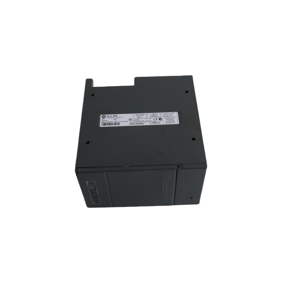
The Allen-Bradley 1746-P2 is a chassis-mounted power supply for SLC 500 systems.It provides 5A at 5V DC backplane power, features selectable 120/240V AC input, and includes a 24V DC auxiliary output for field devices.
The Allen-Bradley MIM105-Q6949 (80026-096-01) is a professional-grade 48V to 24VDC switch-mode power supply designed for PLC systems. It delivers a stable 2A output, ensuring reliable performance for industrial automation and robotics.
We are committed to protecting your privacy. The information collected here is strictly used to provide the requested quotes, technical support, and relevant industrial automation solutions.