


Sale!
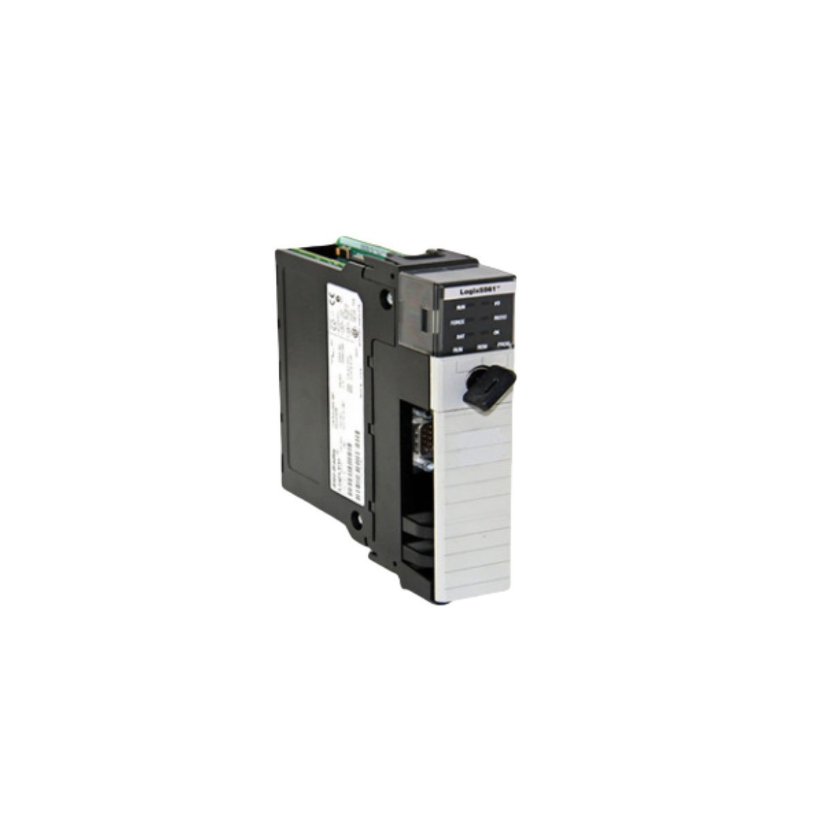
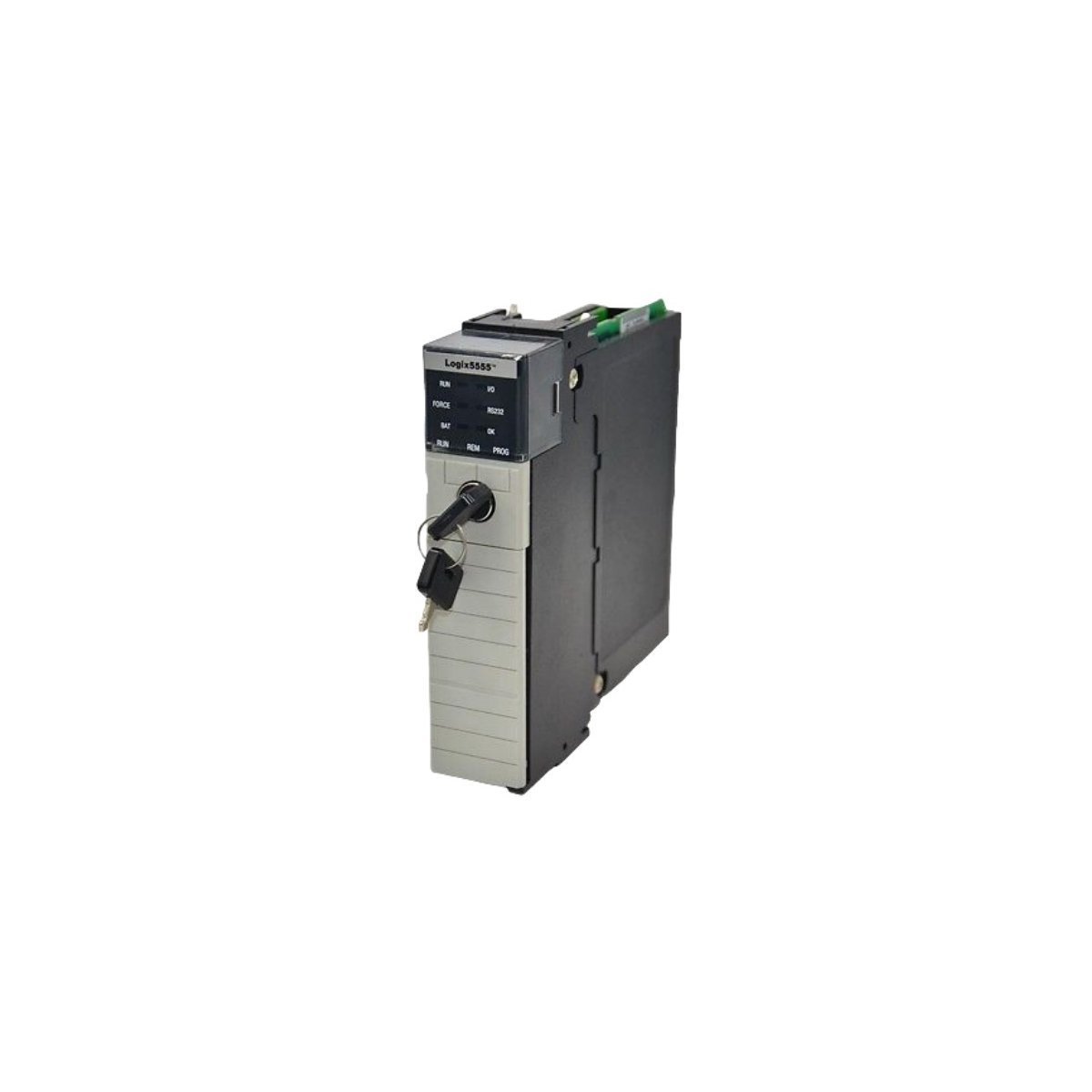
Allen-Bradley 1756-L55M24 GuardLogix Safety Controller Module
The Allen-Bradley 1756-L55M24 is a high-performance GuardLogix controller offering 3.5 MB of non-volatile memory for integrated safety, motion, and discrete control applications.
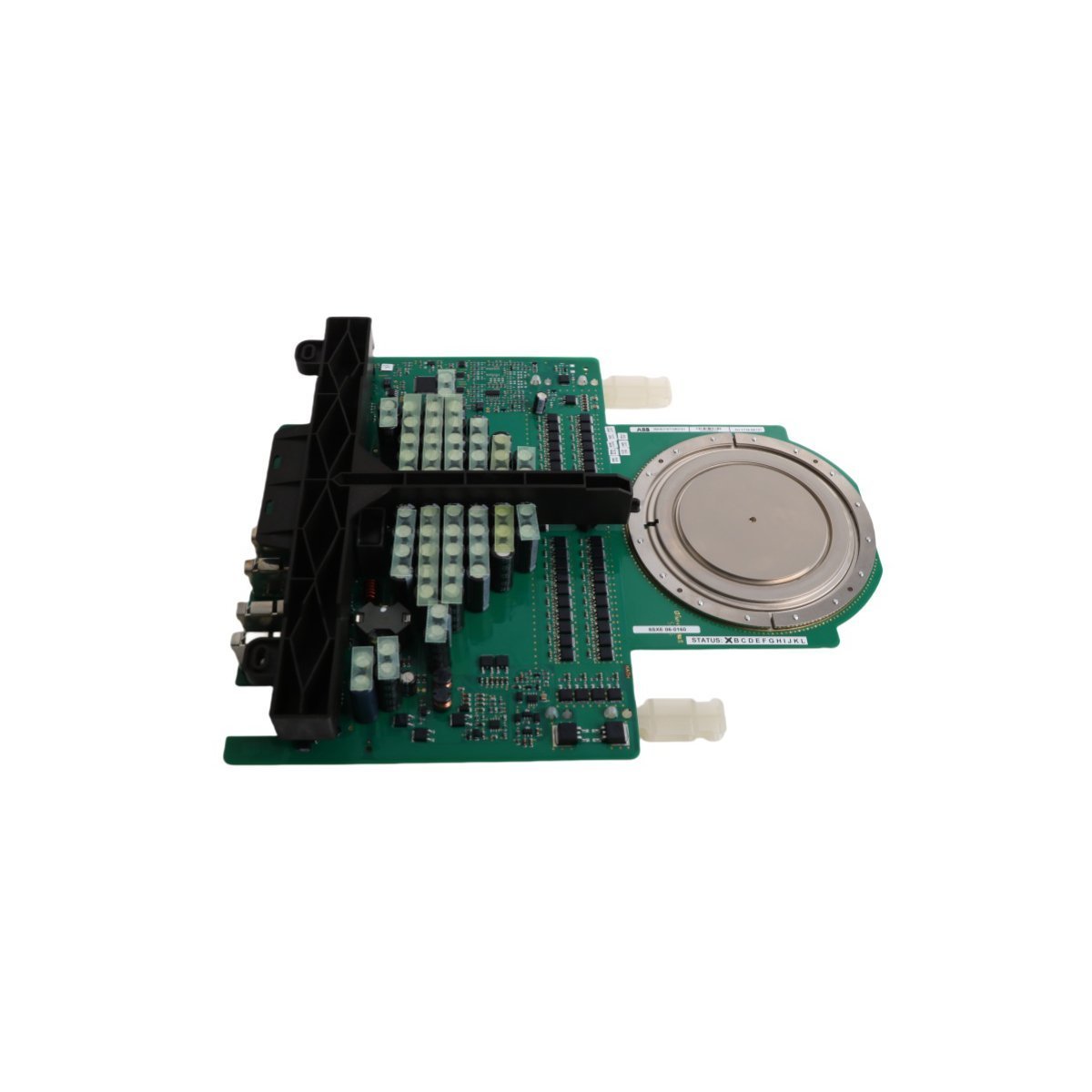
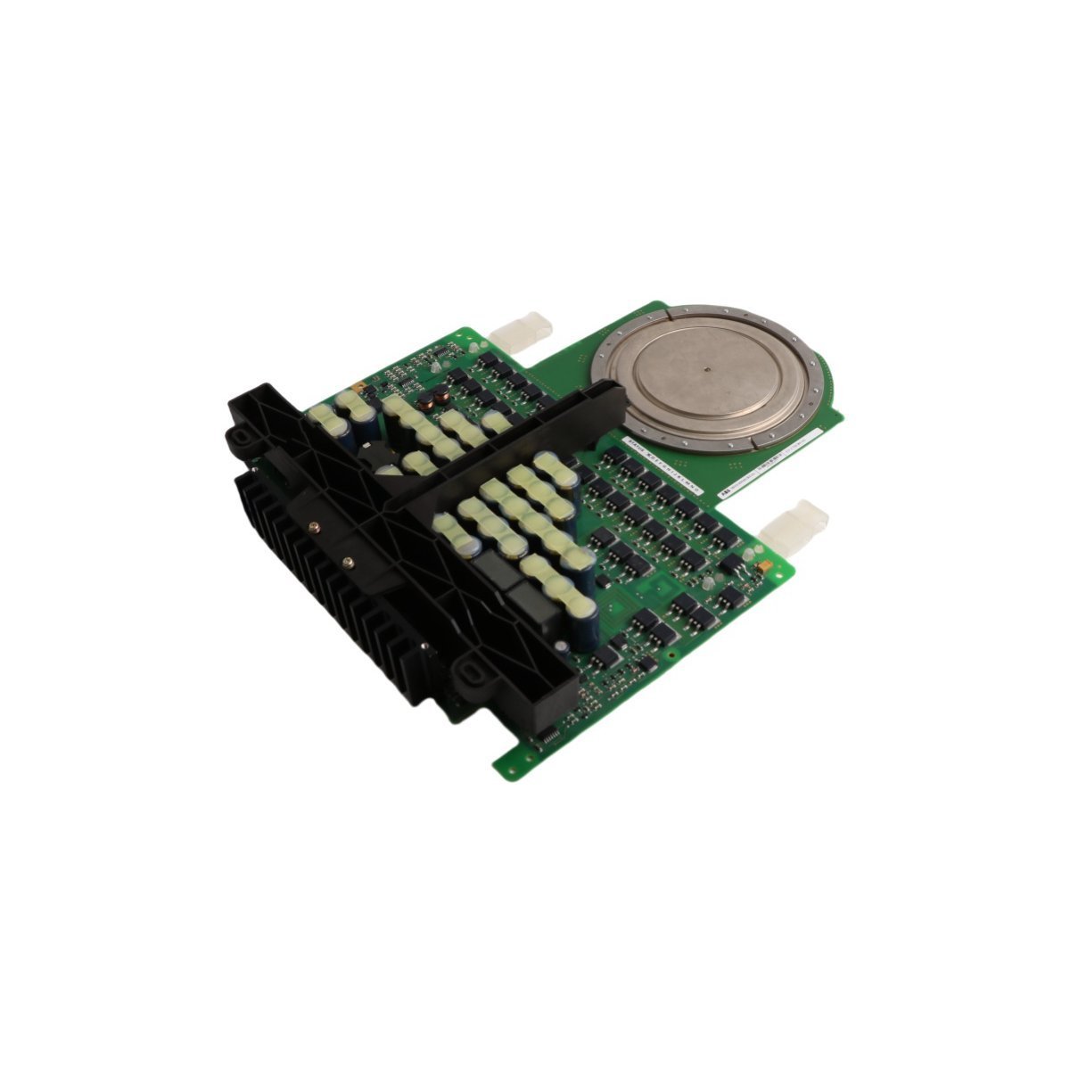
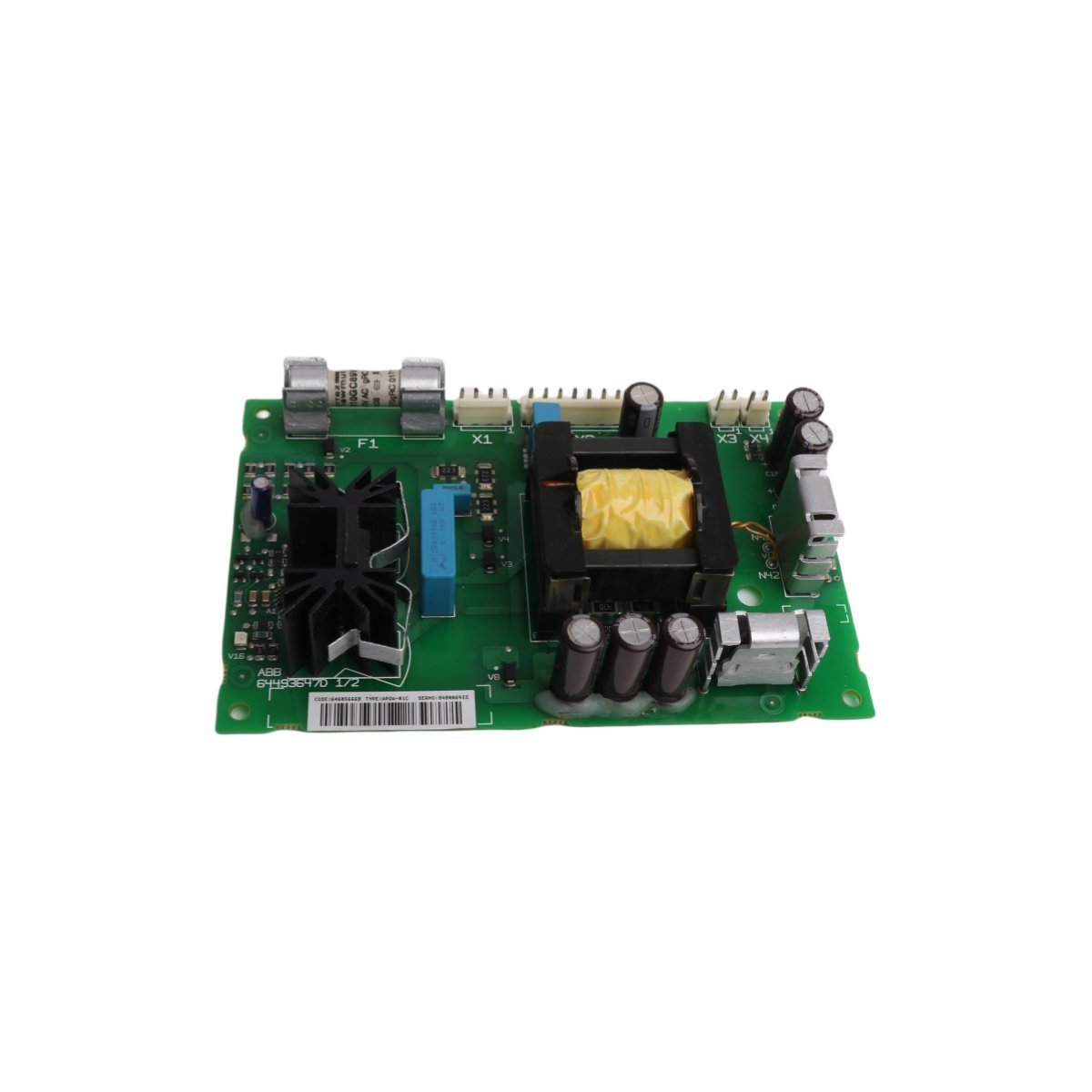
Procure the ABB NAMU-01C 64702475 Hydraulic Control Module, featuring multi-protocol bus connectivity and deterministic DCS backplane processing. Certified original surplus item with full technical warranty. Order your industrial equipment components online now.
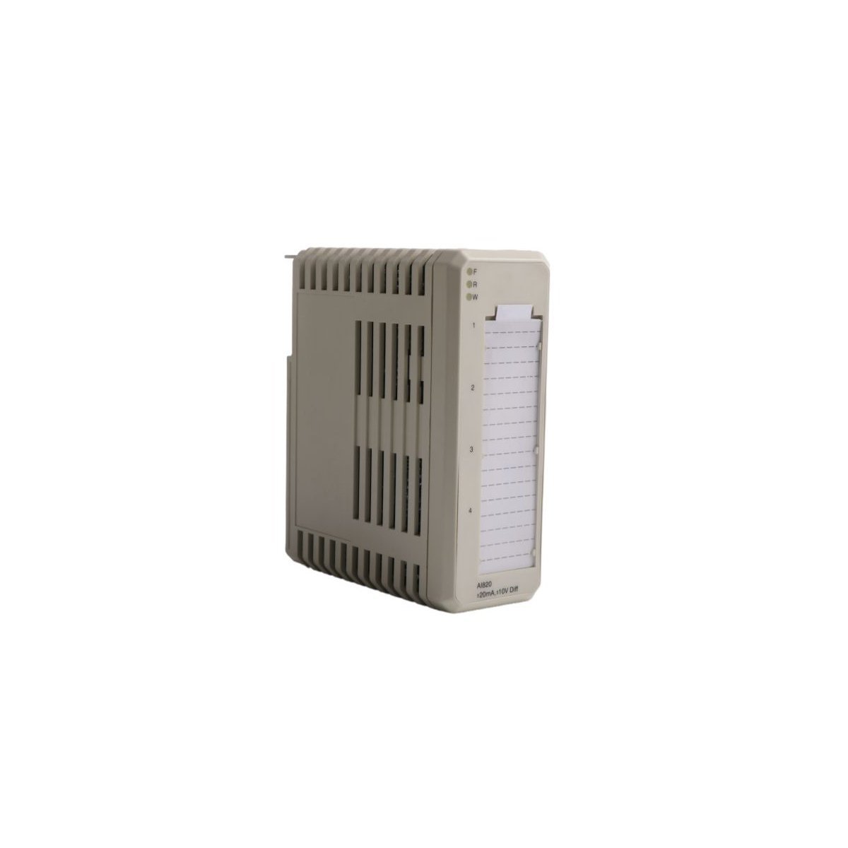
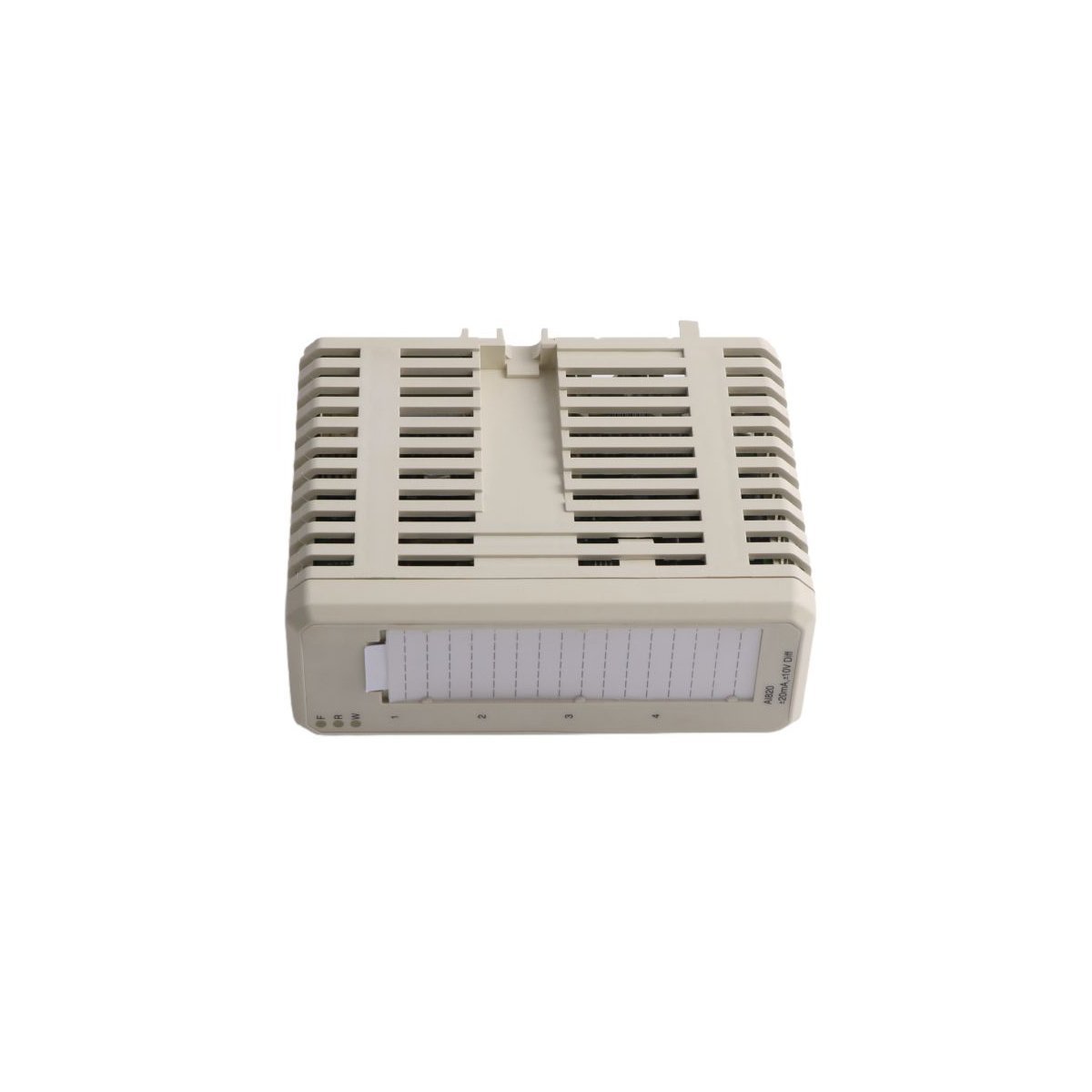
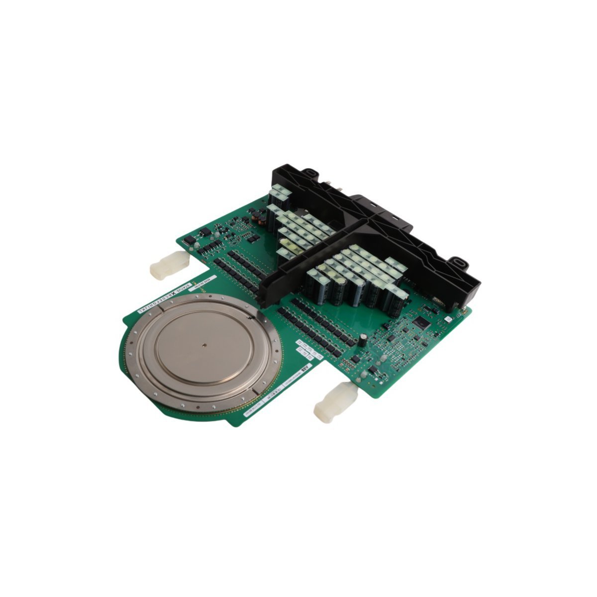
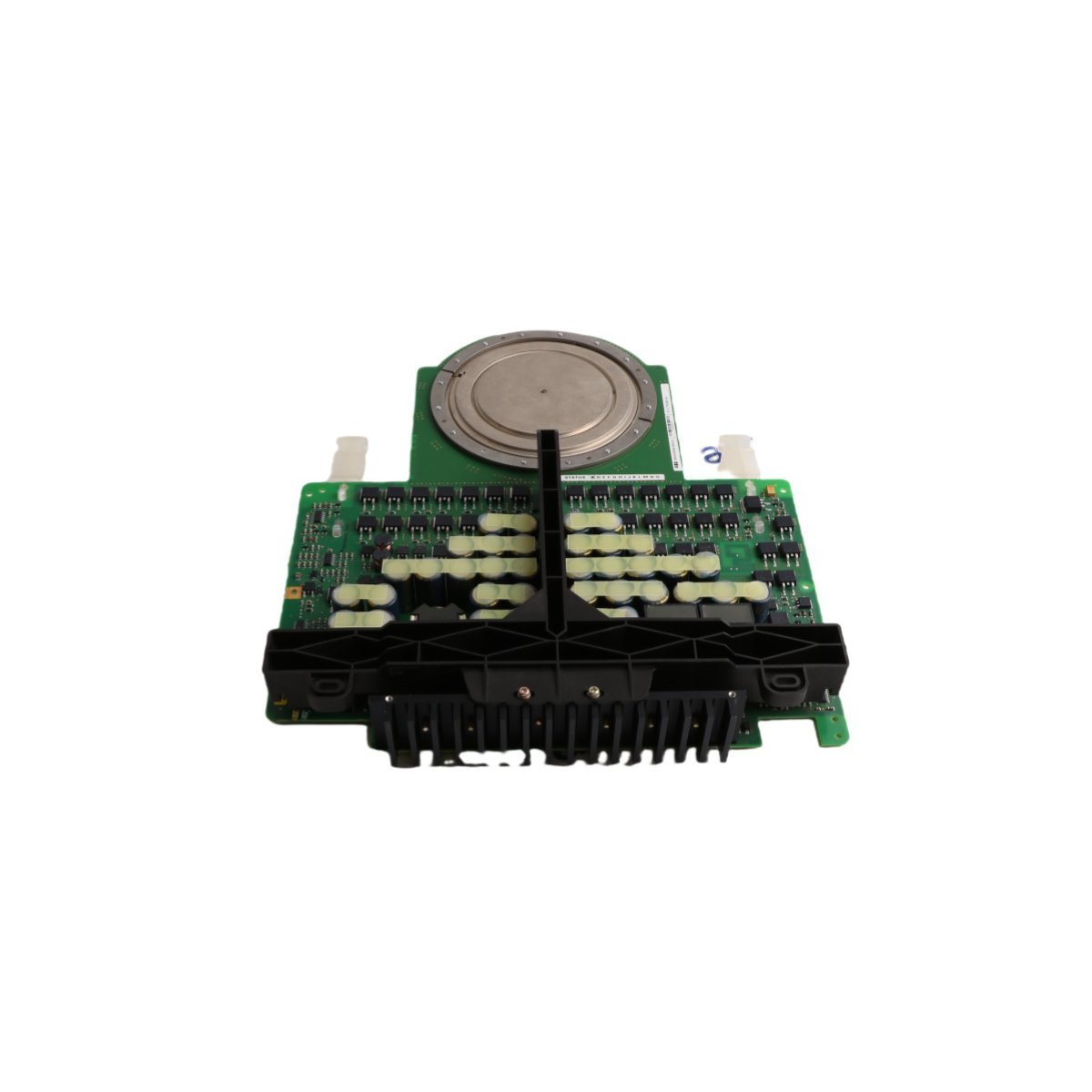
Configured for high-density physical signal execution and fieldbus synchronization in Advant OCS/800xA distributed control networks, the ABB NAMU-01C 64702475 (NAMU-01C Hydraulic Control Module) provides direct deterministic processing for mixed I/O devices. The hardware handles direct electrical routing, processing localized hydraulic valve profiles and interface loops. Operating via a low-power internal backplane draw, the module interfaces with specialized communication pathways to function as a fieldbus routing nodes, establishing direct industrial Ethernet backplane data transfers and execution routines without adding processing latencies to the primary controller.
| Parameter | Specification |
|---|---|
| Model | NAMU-01C 64702475 |
| Brand | ABB |
| Origin | Sweden |
| Weight | 0.38 kg |
| Dimensions | 45 mm x 110 mm x 115 mm |
| Operating Temp | 0 to +55 deg C |
| Power Consumption | <= 6 W |
| System Platform | Advant OCS / 800xA DCS |
| Communication Service | Ethernet router / Fieldbus routing |
| Embedded Interfaces | RS-485, PROFIBUS-DP, CC-Link, DeviceNet |
| Depth Profile | 65 mm casing depth constraints |
| Compliance Matrix | RoHS, WEEE |
The ABB NAMU-01C 64702475 utilizes dedicated backplane bus communication velocity licences to govern synchronous transmission between localized physical terminal blocks and upper-level DCS processors. By implementing optimized hardware pipelines, the unit isolates deterministic Ethernet/IP or Profinet sub-links from variable network jitter. The module features integrated firmware flash compatibility to support continuous operational field upgrades without hardware modification. This communication sub-tier maintains low cyclic timing variations, ensuring that high-density I/O configurations do not degrade processing cycle integrity under peak data throughput.
Q: What are the installation restrictions concerning the onboard open network interfaces during active backplane operations?
A: While the module logic supports standard internal diagnostics, network field buses such as PROFIBUS-DP or DeviceNet must be detached only when line loop power is isolated. Disconnection under active load conditions risks inducing signal spikes or causing bus errors across shared network nodes.
Q: How does the module maintain control parameter state integrity during a complete loss of auxiliary power?
A: The device writes critical tuning profiles and protocol assignments directly to non-volatile flash components during runtime modifications. Upon total loss of 24 VDC power, the internal registers freeze and retain configurations without requiring an internal support battery.
Q: Is a manual firmware flash required when deploying this module into a multi-language platform configuration?
A: No, the core firmware architecture accommodates multi-language definitions inside the resident application image. The upper-level DCS system establishes operator localized data presentation rules automatically upon module discovery on the communication bus.
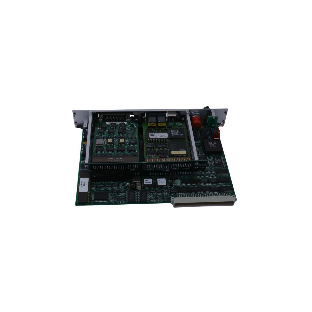
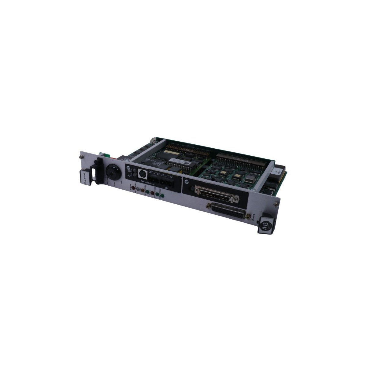
The Allen-Bradley 1785-V40L is a vintage, high-performance PLC-5 processor card designed for seamless slot integration directly into a VMEbus backplane architecture. Featuring 48,000 words of internal user memory and support for 64 KB VME transfer speeds, this versatile controller bridge contains 4 built-in Data Highway Plus (DH+) communication ports alongside an independent Remote I/O (RIO) scanner capable of driving up to 15 external racks. Built with discrete serial port channels (RS-232/422/423) and compliant with strict CE safety certifications, it provides a rugged, highly secure solution for maintaining legacy industrial systems, embedded test setups, and cross-platform automation architectures.


We are committed to protecting your privacy. The information collected here is strictly used to provide the requested quotes, technical support, and relevant industrial automation solutions.