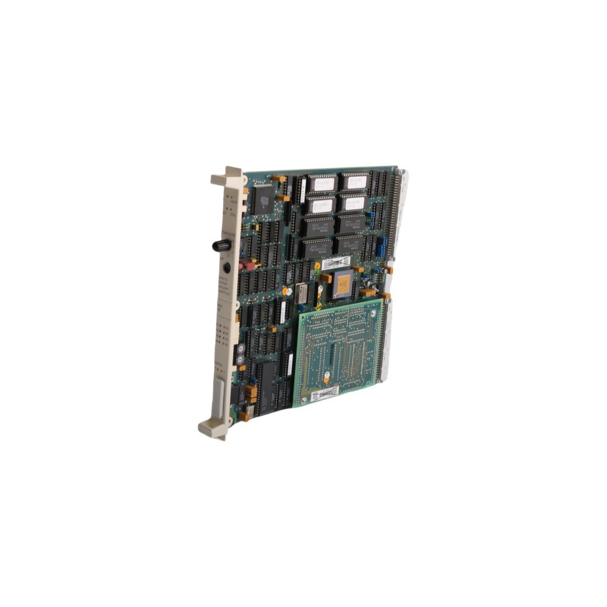
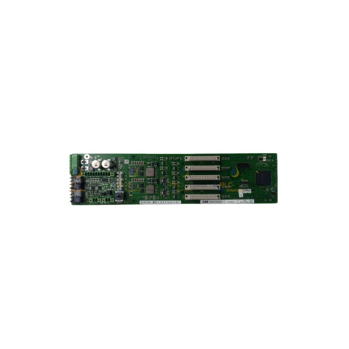
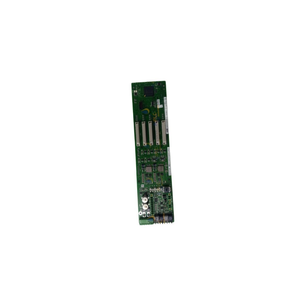
Secure the ABB NGDR-07C Protection Trigger Driver Board, featuring low power consumption and high-speed <=30ms fault protection execution for DCS networks. Factory-verified original surplus with international warranty. Request your formal technical quote today.
Configured for high-density physical signal execution and fieldbus synchronization in Advant OCS/800xA distributed control networks, the ABB NGDR-07C, also cataloged as the NGDR-07C Protection Trigger Driver Board, provides direct deterministic processing for mixed I/O devices. The hardware handles direct electrical routing, processing discrete 24 VDC inputs alongside analog 4-20 mA and 0-10 V loops. Operating via a low-power internal backplane draw, the module interfaces with specialized communication pathways to function as a fieldbus routing nodes, establishing direct industrial Ethernet backplane data transfers and execution routines without adding processing latencies to the primary controller.
Hardware Specifications
Parameter
Specification
Model
NGDR-07C
Brand
ABB
Origin
Sweden
Weight
0.24 kg
Dimensions
230 mm x 138 mm x 20 mm
Operating Temp
-25 to +55 deg C
Power Consumption
<= 4 W
System Platform
Advant OCS / 800xA DCS
Communication Service
Ethernet router / Fieldbus routing
Current Transformer Rating
1 A and 5 A compatible
Fault Protection Execution
<= 30 ms response time
Input Protection Limit
plus/minus 30 V overvoltage protection
Mounting Interface
45 mm DIN-rail compatibility
Industrial Control Determinism and Backplane Performance
The ABB NGDR-07C utilizes dedicated backplane bus communication velocity licences to govern synchronous transmission between localized physical terminal blocks and upper-level DCS processors. By implementing optimized hardware pipelines, the unit isolates deterministic Ethernet/IP or Profinet sub-links from variable network jitter. The module features integrated firmware flash compatibility to support continuous operational field upgrades without hardware modification. This communication sub-tier maintains low cyclic timing variations, ensuring that high-density I/O configurations do not degrade processing cycle integrity under peak data throughput.
Frequently Asked Questions
Q: What are the installation restrictions concerning the removable terminal blocks during live backplane operations?
A: While the module logic supports standard internal diagnostics, wiring termination blocks must be detached only when field loop power is isolated. Removal under active load conditions risks inductive kickback or signal faults across parallel sub-networks sharing the same power rail.
Q: How does the channel control unit respond to input overvoltage conditions exceeding the specified threshold?
A: The onboard clamping circuits provide sustained protection up to plus/minus 30 VDC. If a continuous fault exceeds this threshold, the integrated protective current limiters isolate the damaged sub-channel, preventing localized component failures from migrating to adjacent channels or the central system backplane.
Q: Is a manual firmware flash required when deploying this module into an existing Advant OCS system?
A: The module checks its internal firmware revision against the active master baseline during power-up initialization. If a mismatch is detected, the host DCS system determines compatibility parameters based on system configuration rules, necessitating a manual update only if a specific functional gap exists between sub-components.
Field Installation Guidelines
Ensure the mounting environment complies with standard DIN-rail or sub-rack seating constraints, maintaining a minimum clearance of 50 mm above and below the card casing to permit natural thermal convection.
All field instrumentation cables carrying 4-20 mA or 0-10 V signals must utilize twisted-pair shielded cabling. Ground the shield terminations exclusively at the control cabinet entry ground bar. Do not loop ground paths or ground both ends of the shield to eliminate ground potential loops.
Verify the nominal incoming voltage parameters remain within the specified operating thresholds using a calibrated digital multimeter before engaging the primary supply breaker.
Strip field wiring insulation strictly to a depth of 7 mm. Insert fully into the screw terminals and torque each connection to 0.5 Nm to prevent high-resistance connection points or loose contacts.
Secure the ABB PFSK130 3BSE002616R1 Channel Control Unit, featuring low 4 W consumption and high-precision mixed I/O processing for Advant OCS/800xA platforms. Factory-verified original surplus with international warranty. Request your formal technical quote today.
Procure the ABB NAMU-01C 64702475 Hydraulic Control Module, featuring multi-protocol bus connectivity and deterministic DCS backplane processing. Certified original surplus item with full technical warranty. Order your industrial equipment components online now.
The Allen-Bradley 1769-L36ERM is a CompactLogix 5370 PAC processor featuring 3 MB user memory and 16-axis motion control. Brand New, Original Stock, ready for worldwide distribution.
The ABB DI651 3BHT300026R1 is a 32-channel digital input module for the Advant OCS 800xA series. It features 24V DC operation, 1500V AC isolation, and a wide operating temperature range for professional DCS applications.
The ABB AI835A 3BSE051306R1 is an 8-channel S800 analog input module for thermocouples and mV signals. It features 0.1 μV resolution, cold junction compensation, and galvanic isolation for high-precision temperature monitoring in 800xA systems.
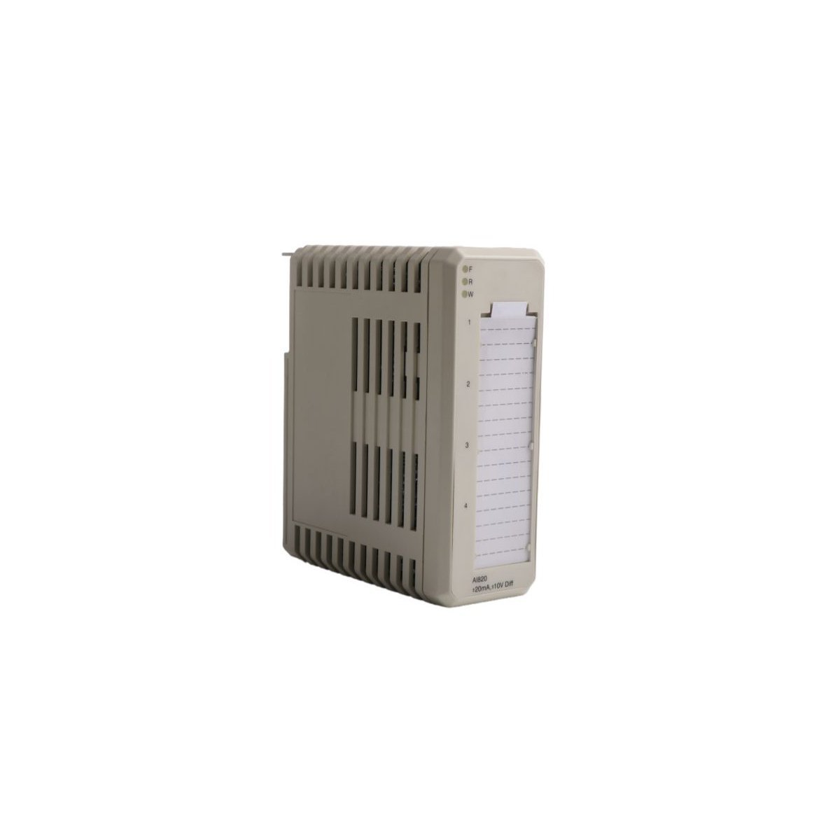
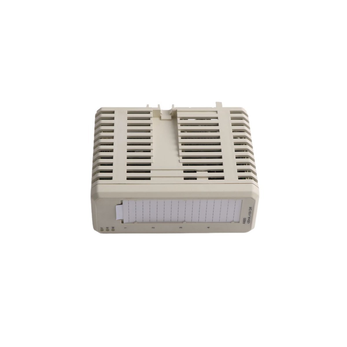
The ABB AI820 is a 4-channel bipolar analog input module for S800 I/O systems. It features 14-bit resolution, supports both voltage and current signals, and provides 30V DC overvoltage protection for reliable industrial data acquisition.
The ABB TK811V015 (3BSC950107R1) is a 1.5-meter Plastic Optical Fiber cable designed for Advant OCS and 800xA systems. It provides EMI-immune, 650 nm wavelength communication for AC 800M controllers in demanding industrial environments.
The ABB AI820 3BSE008544R1 is a 4-channel analog input module for S800 I/O systems. It features 14-bit resolution and group isolation for precision DCS monitoring.
The ABB UDD406A 3BHE041464R0101 is a high-performance digital input module for Advant OCS and 800xA systems. It offers robust network interfacing and precise signal acquisition for industrial drive control. This Sweden-made board ensures reliable real-time monitoring and maximum energy efficiency in complex automation environments.
The ABB 5SHY3545L0014 (3BHE023784R0001) is a 4500V, 3500A IGCT module. It offers fiber-optic triggering and high-speed switching for ACS6000 drives and medium-voltage power systems.
The ABB PM864AK01 (3BSE018161R1) is a high-speed MPC862 processor unit designed for AC 800M and 800xA control systems.It features 32MB RAM, dual Ethernet ports, and supports up to 96 I/O modules, providing reliable real-time execution for demanding industrial automation tasks
We are committed to protecting your privacy. The information collected here is strictly used to provide the requested quotes, technical support, and relevant industrial automation solutions.