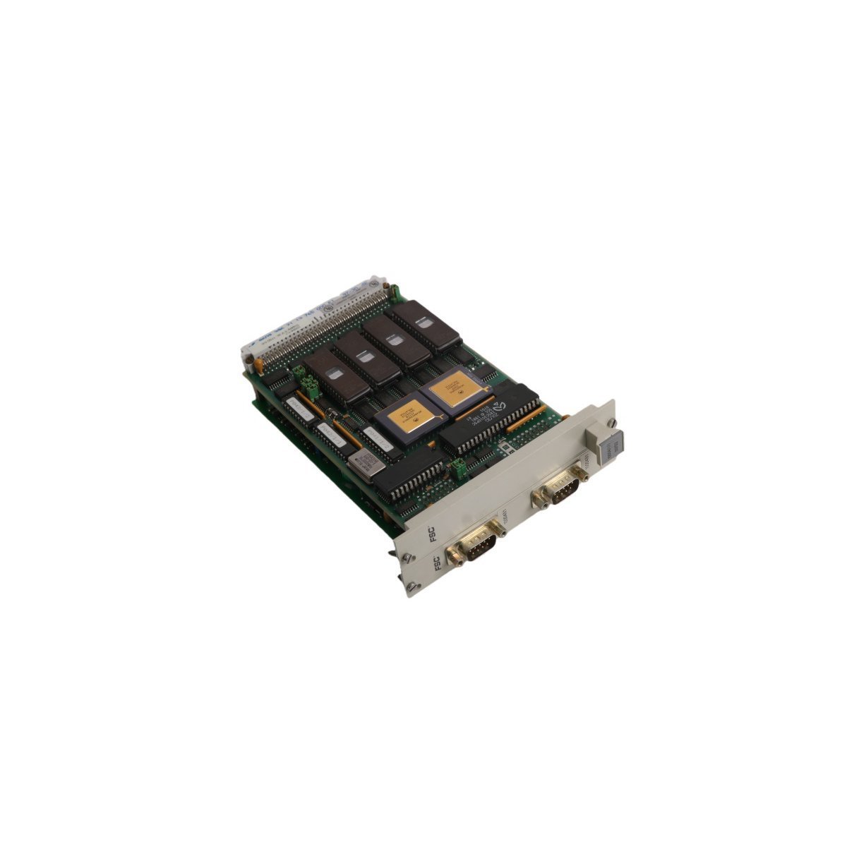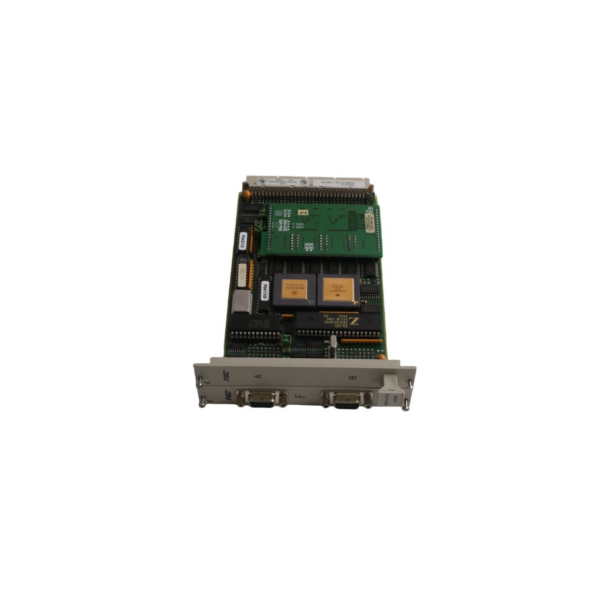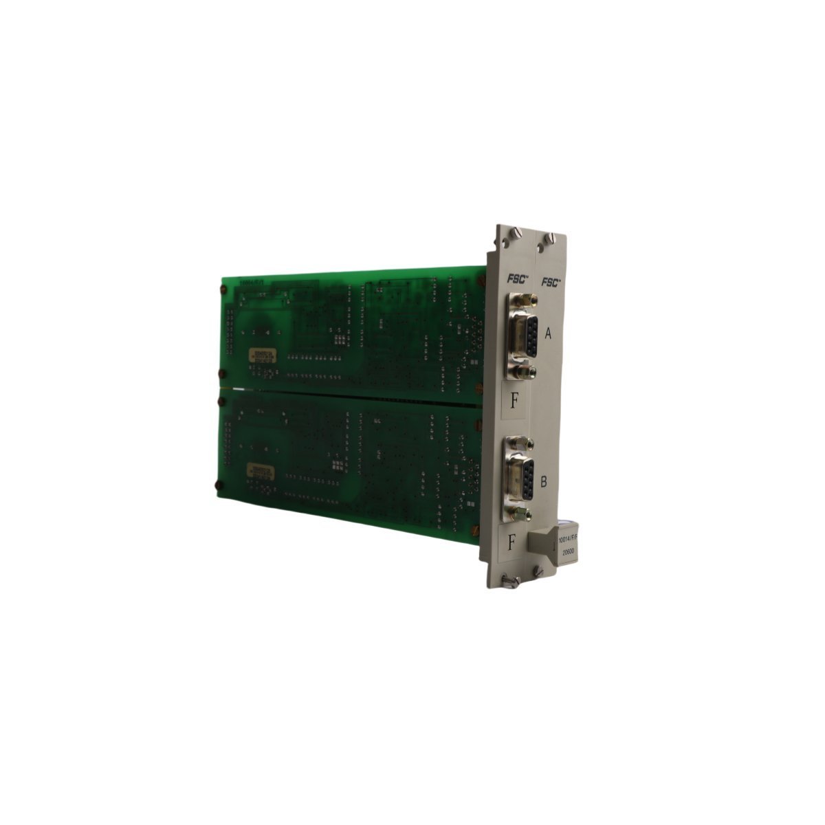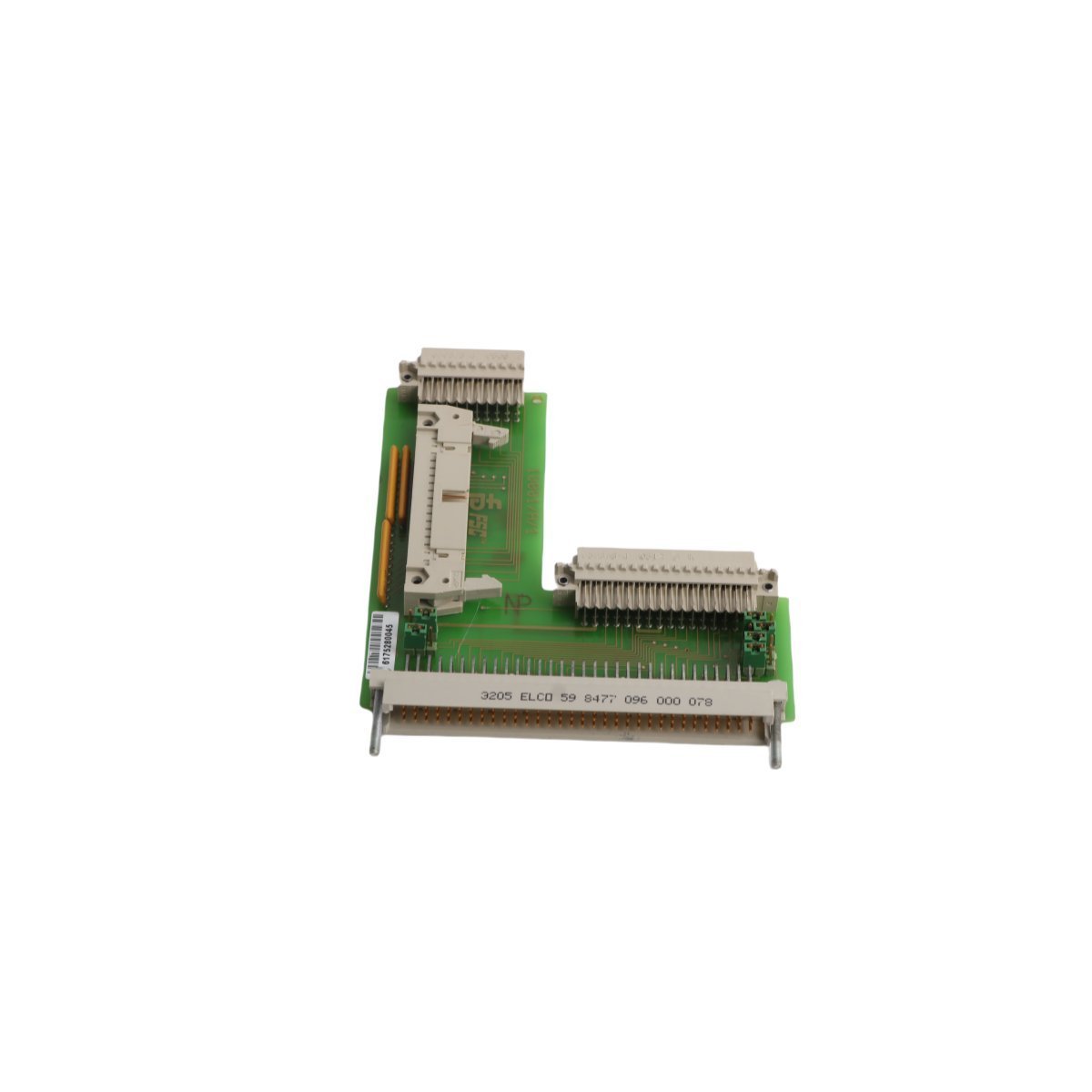
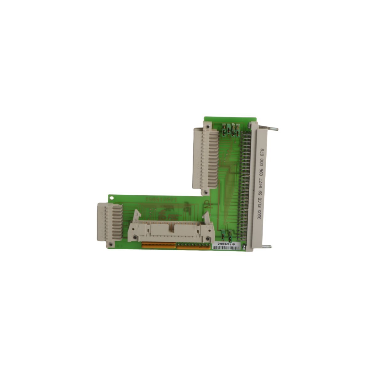
Honeywell 10001/A/1 Vertical Bus Driver Card
Hardware Specifications
| Parameter | Specification |
|---|---|
| Model | 10001/A/1 |
| Brand | Honeywell |
| Origin | USA |
| Weight | 0.06 kg |
| Dimensions | 12.8 x 10 x 1 cm |
| Operating Temp | Standard Industrial |
| Power Consumption | Not Specified |
| Module Type | Vertical Bus Driver Card |
Process Control and DCS Connectivity
Signal integrity is primarily maintained within the DCS environment through the systematic implementation of dedicated input termination pathways. Consequently, data acquisition is facilitated by the 10001/A/1, whereby field sensor signals are processed and subsequently routed to the control cabinet backplane. Furthermore, channel-to-channel isolation is consistently utilized so that, as a result, common-mode noise propagation is effectively prevented. In this manner, it is ensured that 4-20 mA HART loop protocol signals or discrete inputs are accurately translated. Additionally, cold junction compensation (CJC) is managed via the associated termination logic; meanwhile, loop impedance is calibrated to match specific field requirements. Moreover, data transmission is executed through standardized backplane interfaces. In addition, these interfaces are continuously monitored, thereby minimizing signal attenuation across long-distance field wiring. Furthermore, by adhering to these protocols, system stability is enhanced; likewise, operational accuracy is preserved throughout the signal path.
Frequently Asked Questions
Q: Is the 10001/A/1 card compatible with hot-swapping procedures in an active chassis?A: Hot-swapping is not supported for this module; power must be removed from the backplane segment prior to the insertion or extraction of the card to prevent damage to the bus driver circuitry.Q: How is the physical grounding of the bus driver card established?A: Grounding is established through the mechanical connection between the module mounting tabs and the chassis backplane, ensuring a common potential for all signal shielding.Field Installation Guidelines
The 10001/A/1 is designed for installation within a standard control cabinet environment on a horizontal or vertical mounting rail.- Mounting: The assembly must be securely fastened to the backplane slot to ensure electrical continuity. Mechanical vibrations should be minimized by tightening all retention screws to the specified torque.
- Wiring: Shielded cabling is required for signal runs to mitigate electromagnetic interference (EMI). The cable shields should be landed at the designated chassis ground busbar to maintain signal reference integrity.
- Environmental Considerations: Exposure to high humidity or corrosive atmospheres must be avoided. If installed in environments with ambient temperatures exceeding 50 deg C, forced air ventilation is required to ensure the thermal dissipation of the assembly is sustained.