You are here:
SKU: CMA131 3DDE300411

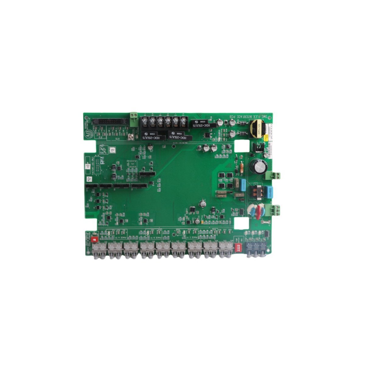
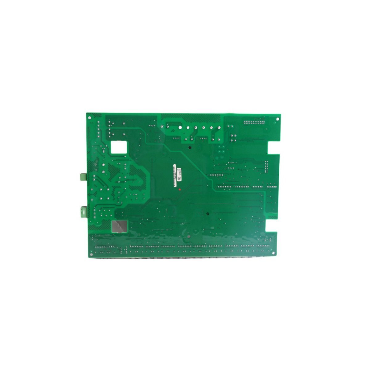
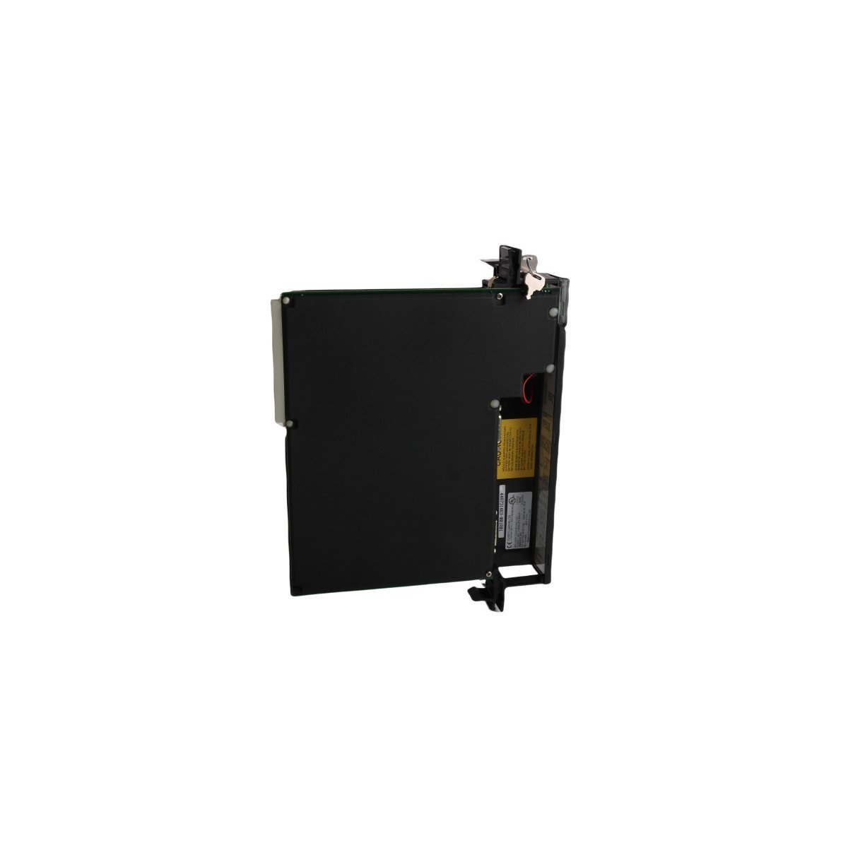
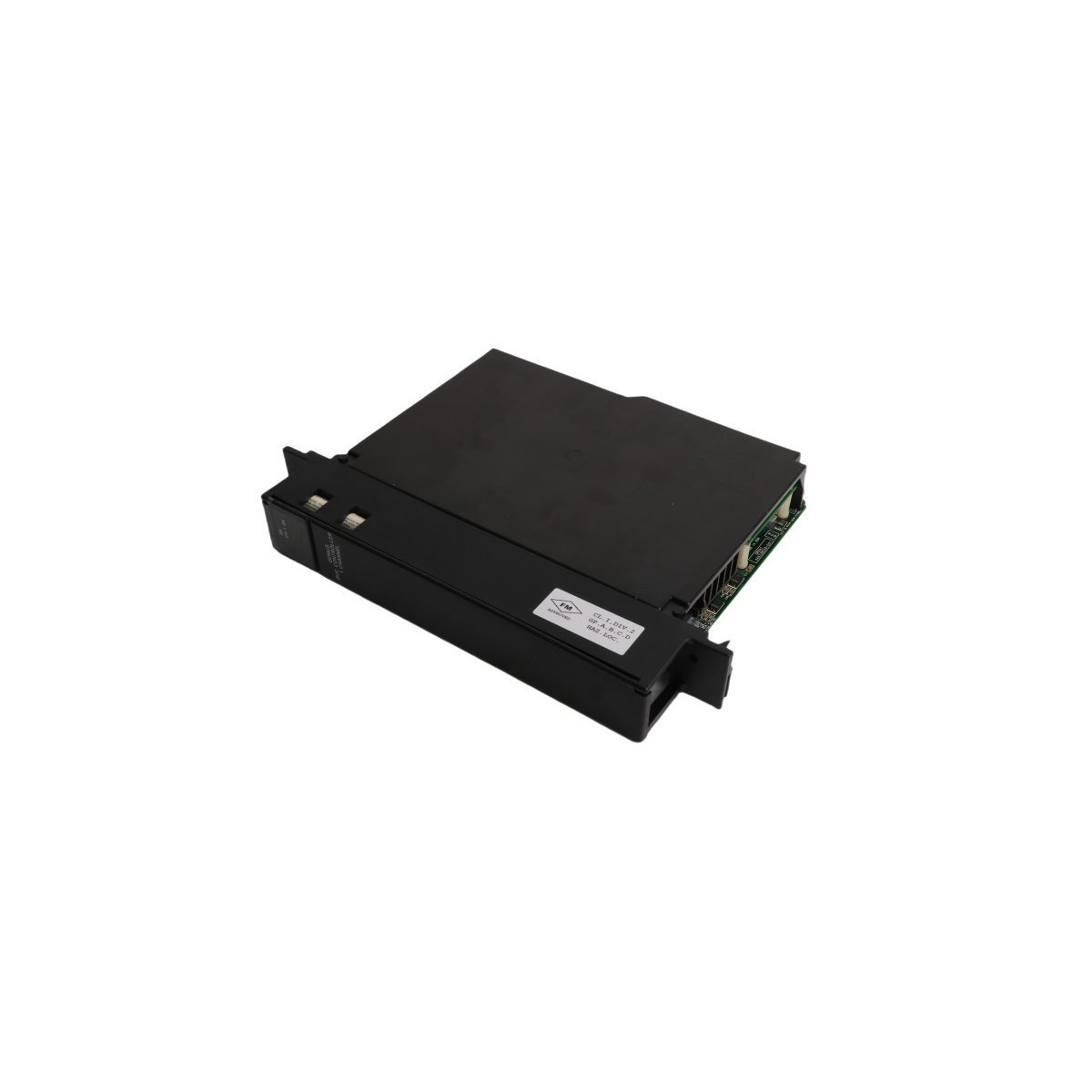
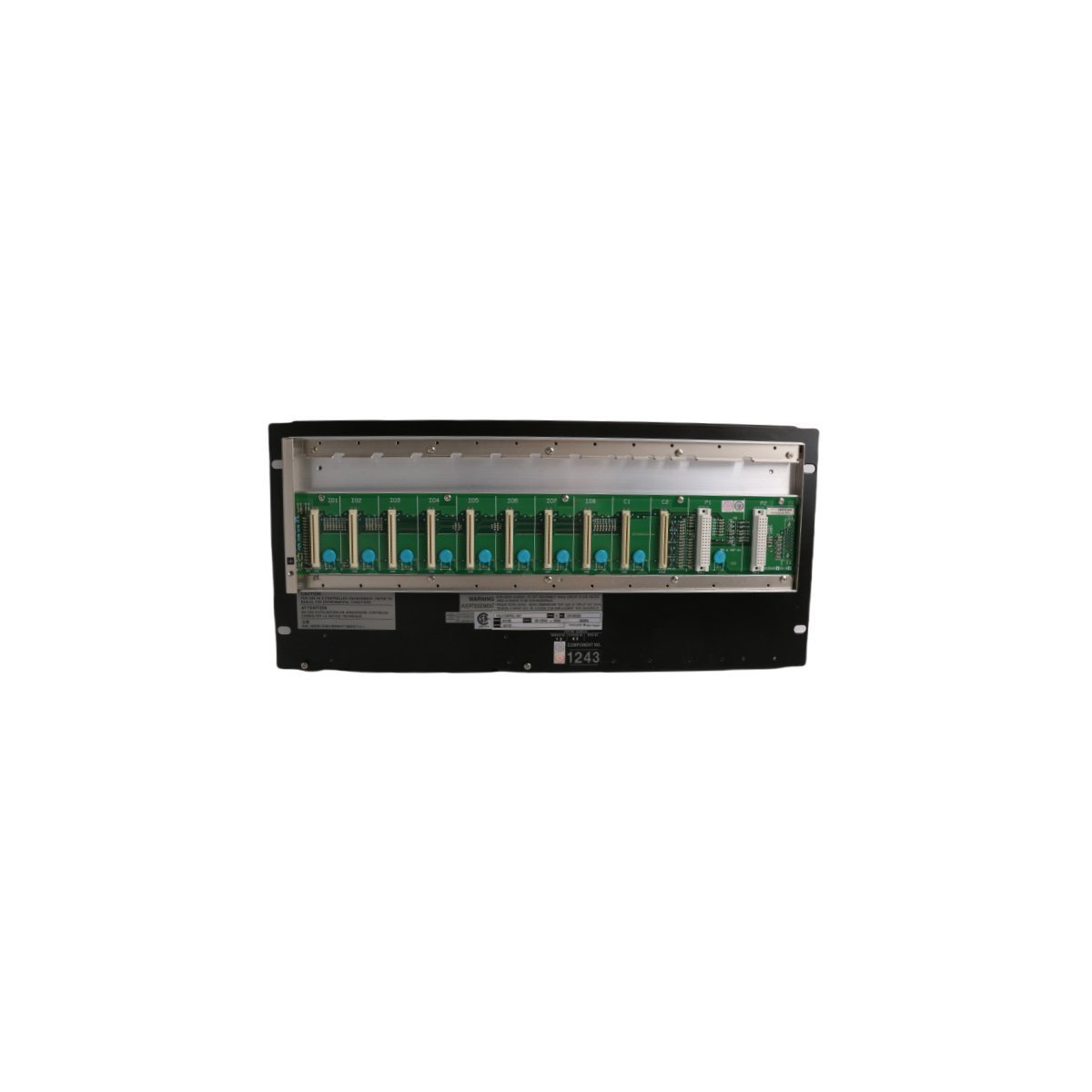
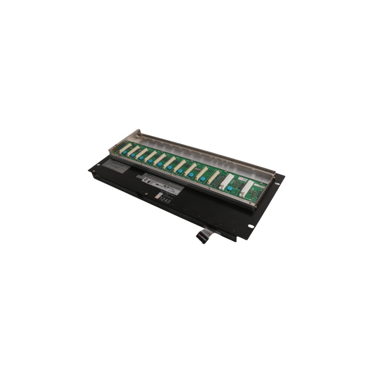
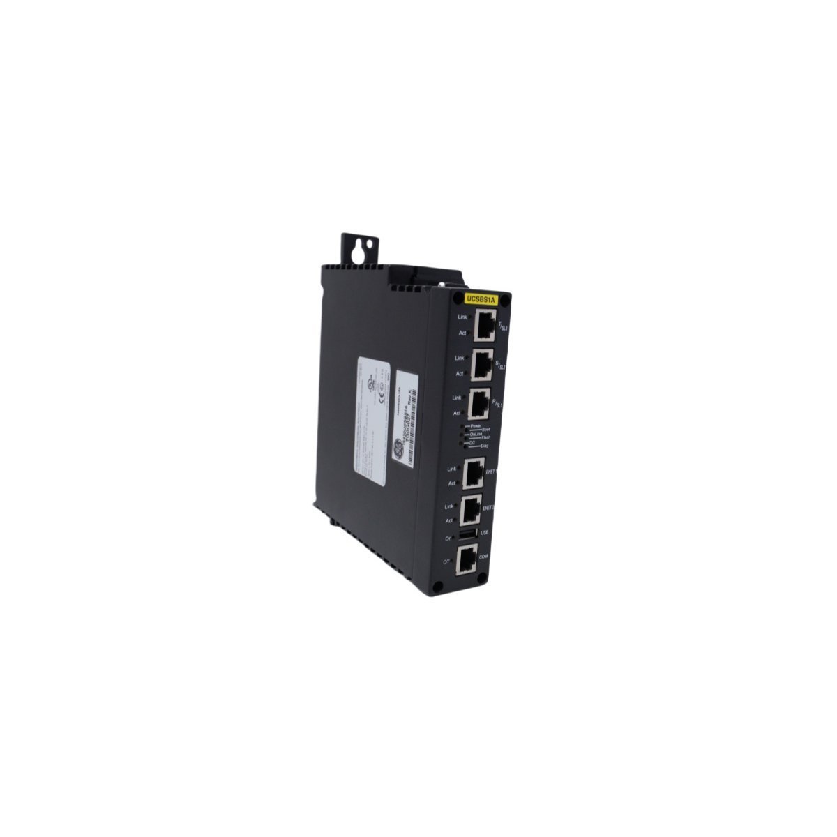
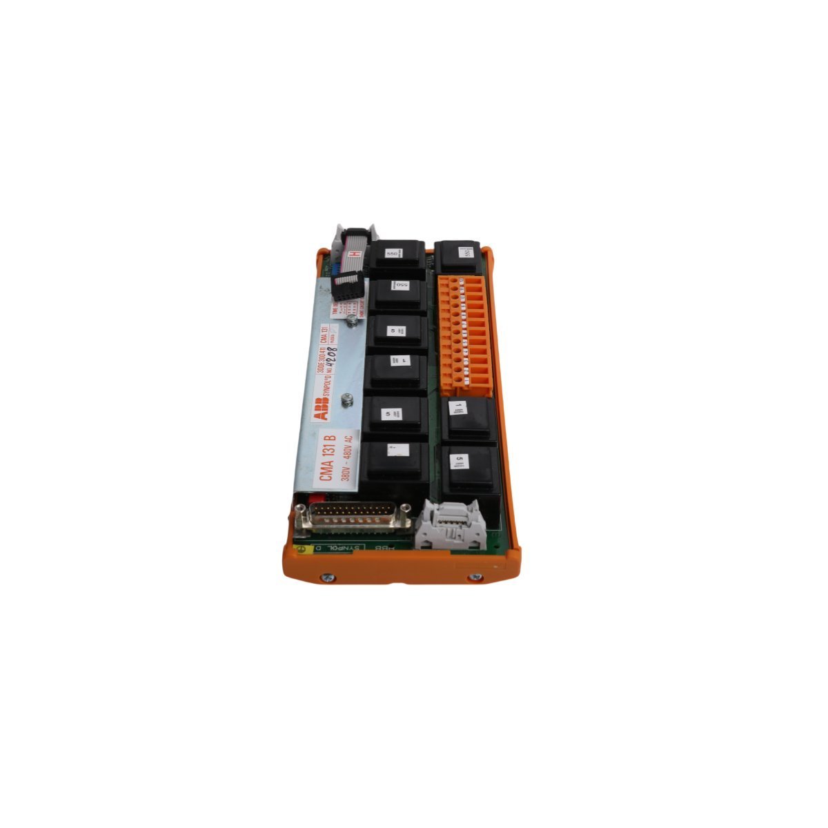
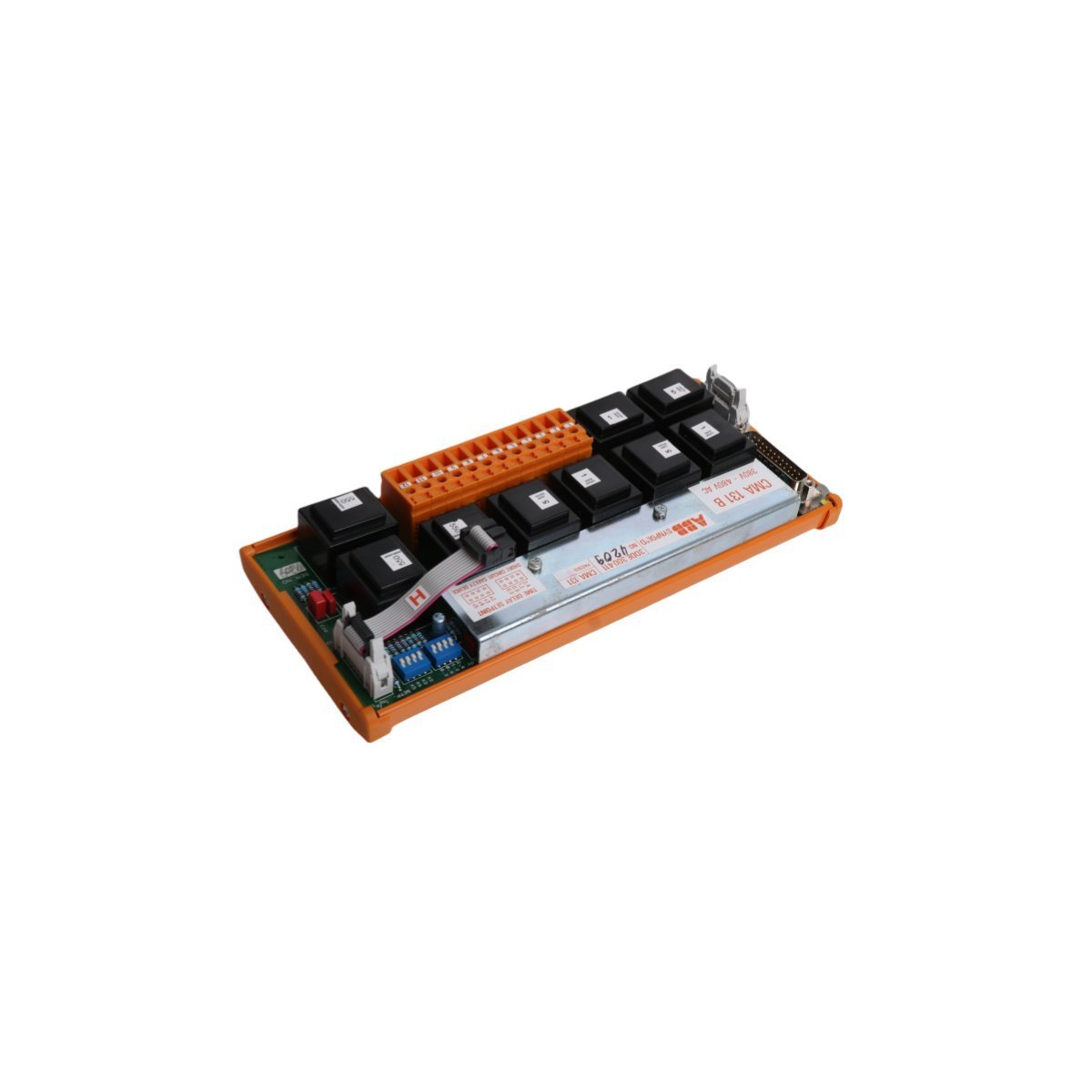
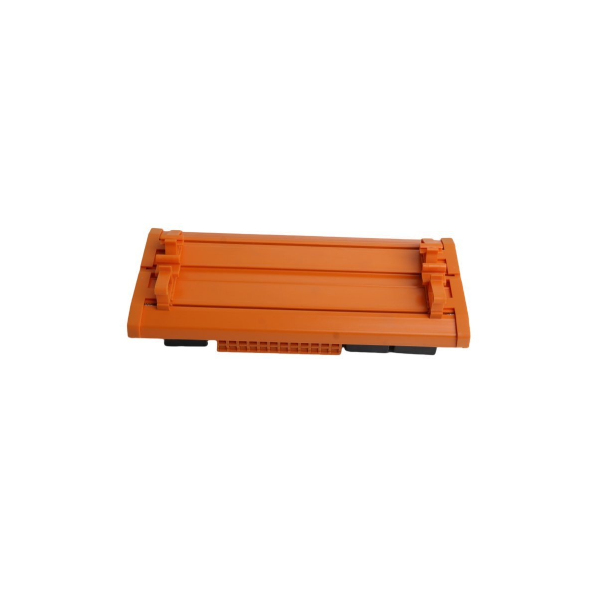
ABB CMA131 3DDE300411 Synpol D Control Module

Purchase the ABB CMA131 3DDE300411 communication module designed for Synpol D and industrial DCS infrastructure. Brand New, Original Stock with Global Shipping. Maintain your automation system uptime today.

Designed for critical excitation, speed, and positioning verification loops within industrial automation networks, the ABB CMA131 3DDE300411 (CMA131) Interface Module provides deterministic processing. As part of specialized control lines (such as Synpol D systems), this high-reliability unit delivers real-time data translation for generators, high-power servo assemblies, and industrial processors.

Hardware Specifications

ParameterSpecification
ModelCMA131 3DDE300411
BrandABB
OriginSweden
Weight0.35 kg
Dimensions15.2 x 3.3 x 5.5 cm
Operating Temperature0 to 60 deg C (standard industrial enclosure)
System CategoryDCS / Large-Scale Automation
Power Requirement24 VDC nominal
Communication StandardIEEE 802.3 Compliant (10Base-T Ethernet / System Bus)
Cable RequirementsShielded Twisted Pair (STP, Category 3, 4, or 5)
Media OptionsConfigurable base variants support optical fiber extensions
Status IndicatorsTri-Color Diagnostic LED (Green/Orange/Off)
Product Lifecycle StatusActive / Limited Maintenance Support

Synchronous Signal Management and Deterministic Bus Routing

The CMA131 3DDE300411 hardware serves as a bridge between the high-speed controller backplane and peripheral system devices. Operating on a deterministic 10Base-T communication protocol, the module handles high-frequency encoder tracking, synchronization variables, and generator feedback logic without network collision delays. By leveraging its integrated hardware-level priority queueing, critical safety and speed command sequences bypass standard non-urgent diagnostic packets to protect heavy rotary machinery from desynchronization faults.

Frequently Asked Questions

Q: How should the front-panel status indicator LEDs be interpreted during operation?

A: The tri-color LED maps the physical health of the module: Off indicates a total loss of input supply voltage or a critical internal hardware isolation fault; Green denotes that power is applied and the module is configured; Orange represents a transitional state where power is present and the module is recognized but waiting for a configuration hand-shake from the master controller.

Q: What network cable specifications are required to guarantee electromagnetic noise immunity?

A: The hardware requires Category 3, 4, or 5 Shielded Twisted Pair (STP) data lines. The cable shield must be continuous and grounded at the structural entry bulkhead panel of the enclosure to shield the internal data transceiver circuits from electromagnetic fields generated by adjacent high-voltage servo lines.

Q: Can this unit handle fiber optic system bus extensions directly?

A: Yes, certain variant sub-assemblies under the CMA131 architectural umbrella support multi-mode or single-mode fiber transceivers. Single-mode optical fiber configurations are capable of supporting long-distance lines up to 90 km, while multi-mode fibers are optimal for cost-effective short-range links up to 10 km.


Field Installation Guidelines

  • Chassis Attachment and Mechanical Locking: Slide the module onto the dedicated system base plate or chassis slot guide. Ensure the rear gold-plated connector pins remain perfectly perpendicular to the receptacle before pressing the unit firmly into place, then secure all integrated retaining screws.
  • DC Input Voltage Routing: Source the module control circuit power from an isolated 24 VDC power supply. Route the power routing leads via distinct conduits separate from the high-current 3-phase motor power lines to mitigate inductive voltage cross-talk.
  • Thermal Layout Planning: Install the hardware inside a well-ventilated control cabinet. Keep a clear zone of at least 50 mm above and below the module assembly to promote natural convection cooling and ensure internal ambient conditions do not exceed the 60 deg C ceiling.
  • System Grounding Requirements: Establish a low-impedance connection between the chassis base plate and the main cabinet earth ground bar. The grounding strap resistance must measure below 1 ohm to ensure stray electrostatic dissipation pathing functions safely.