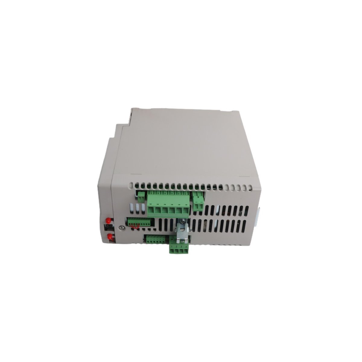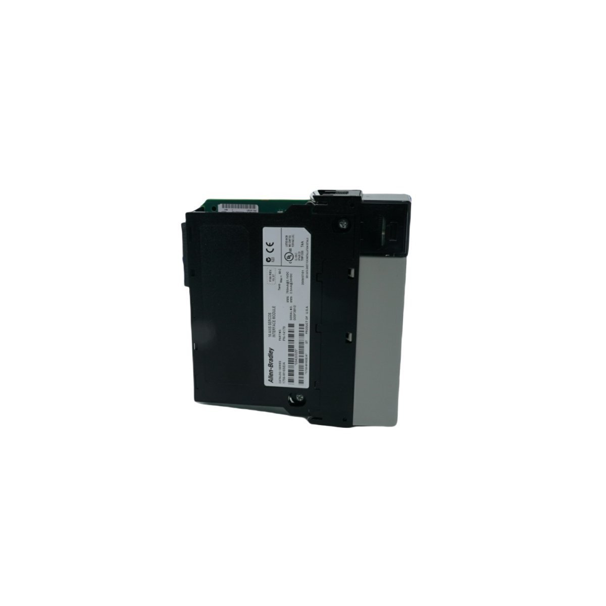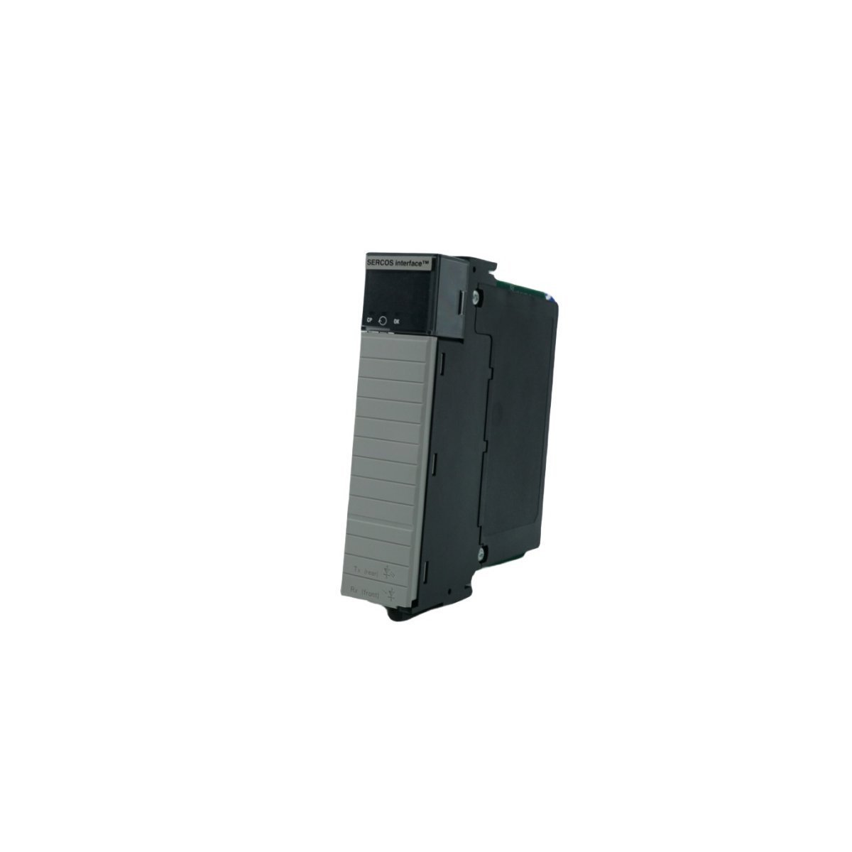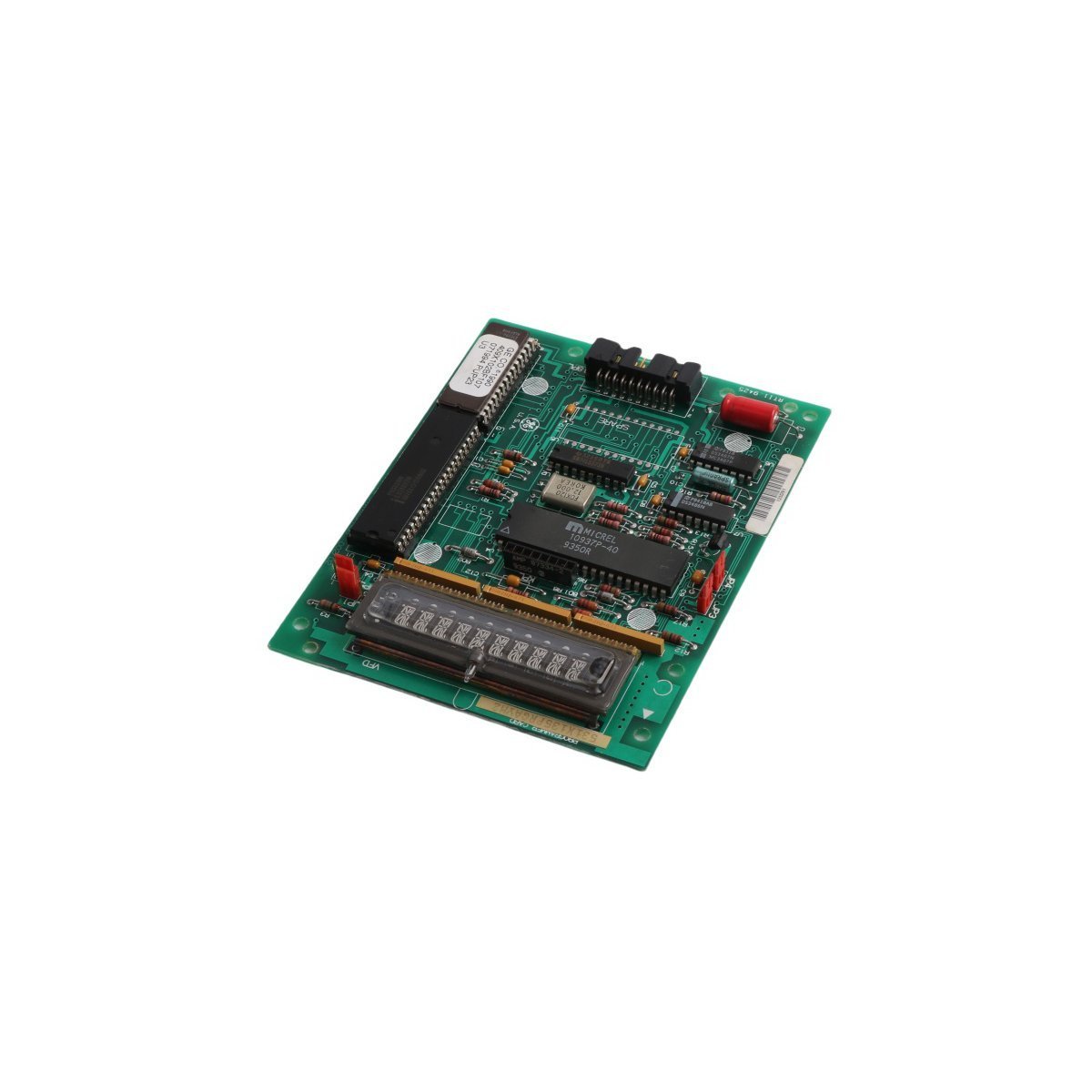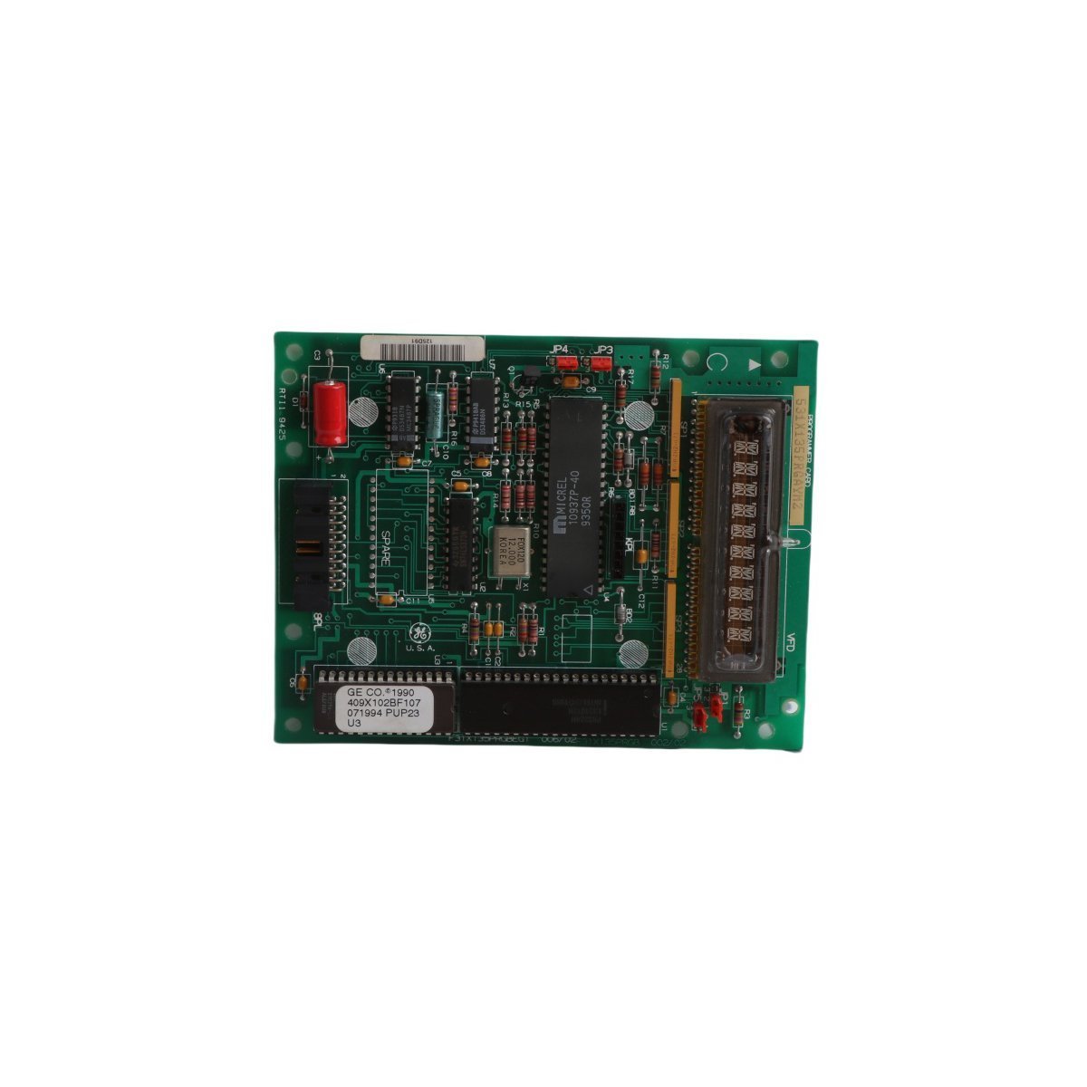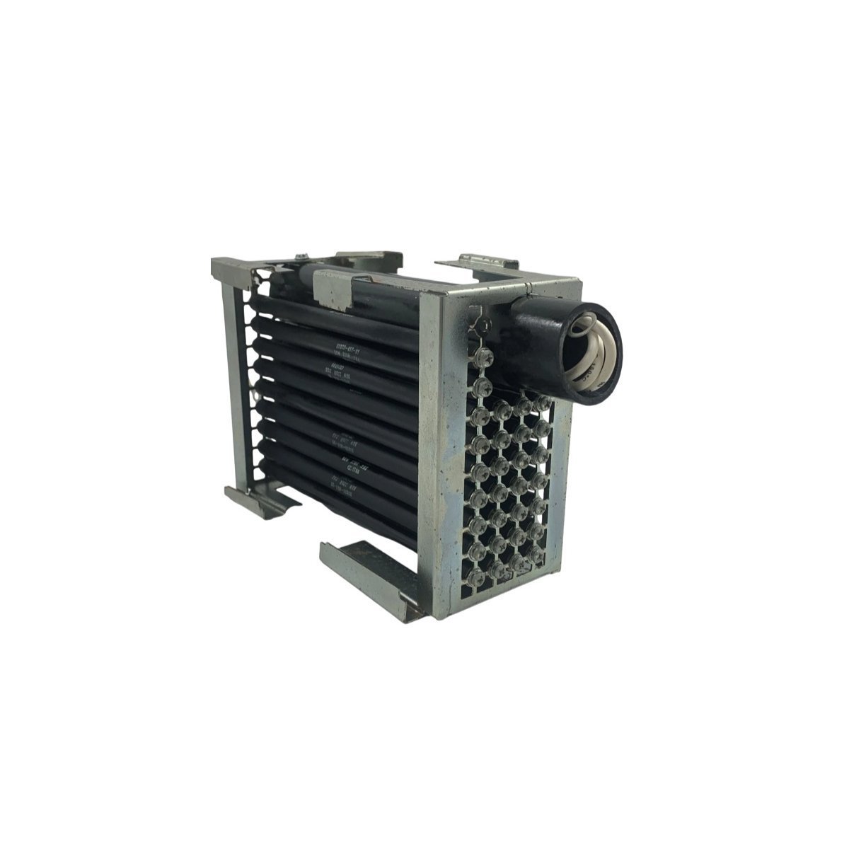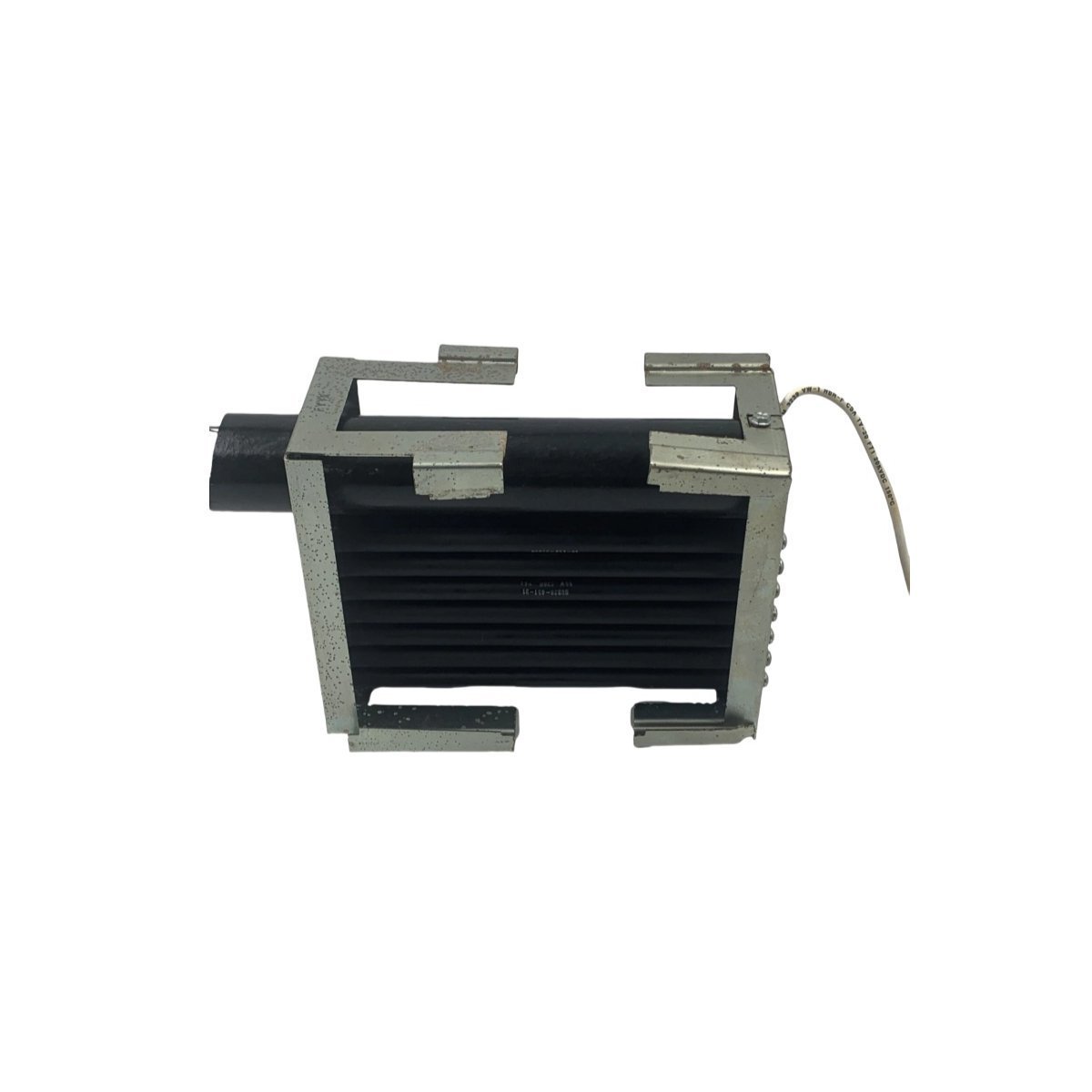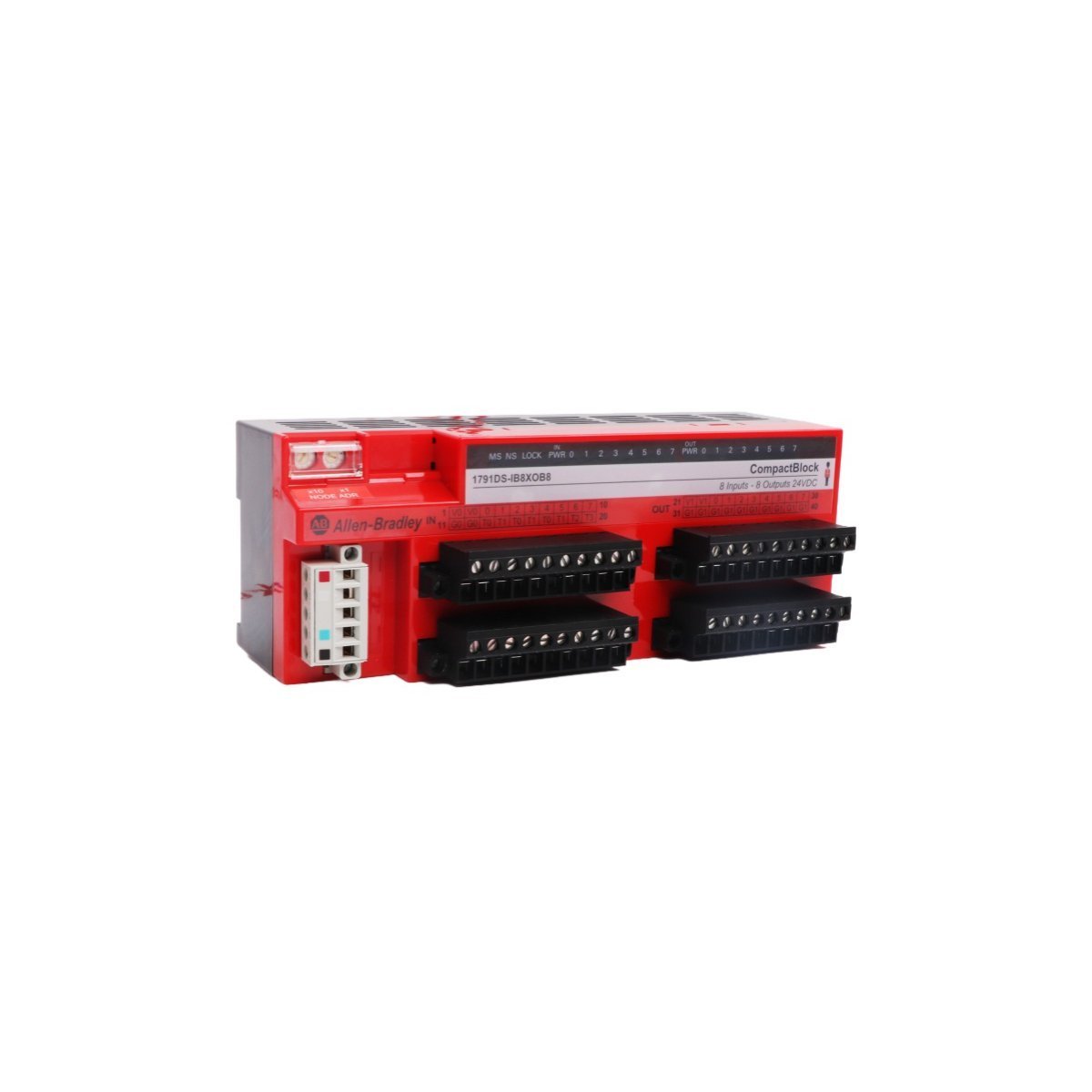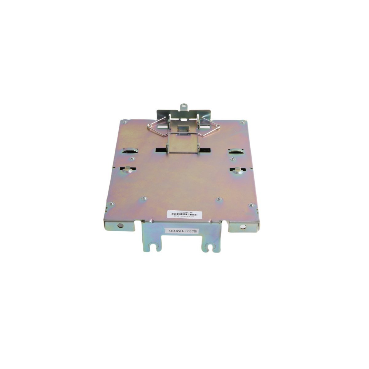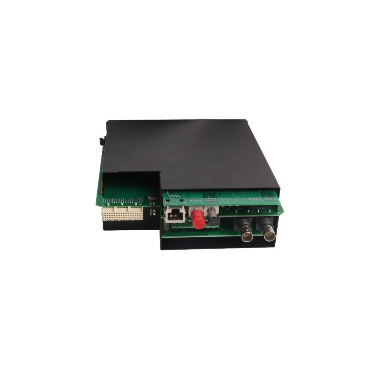
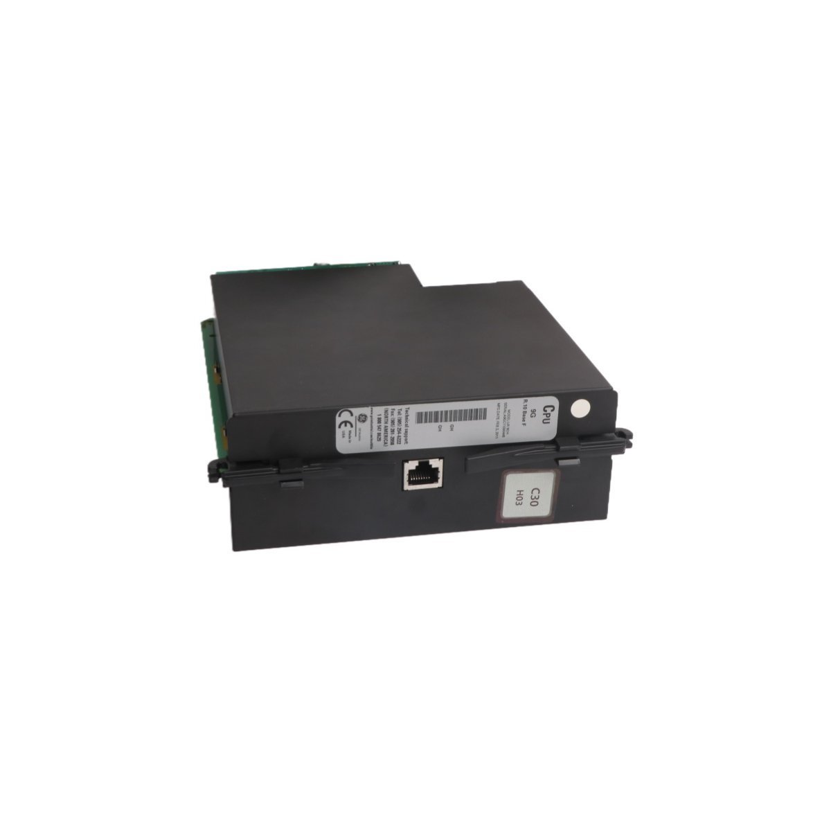
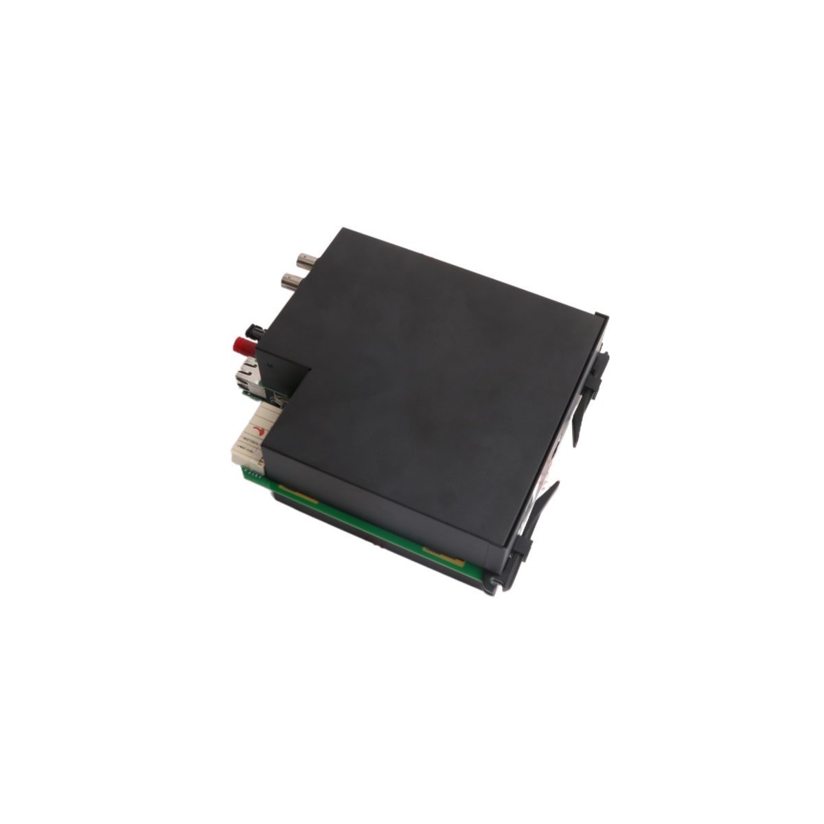
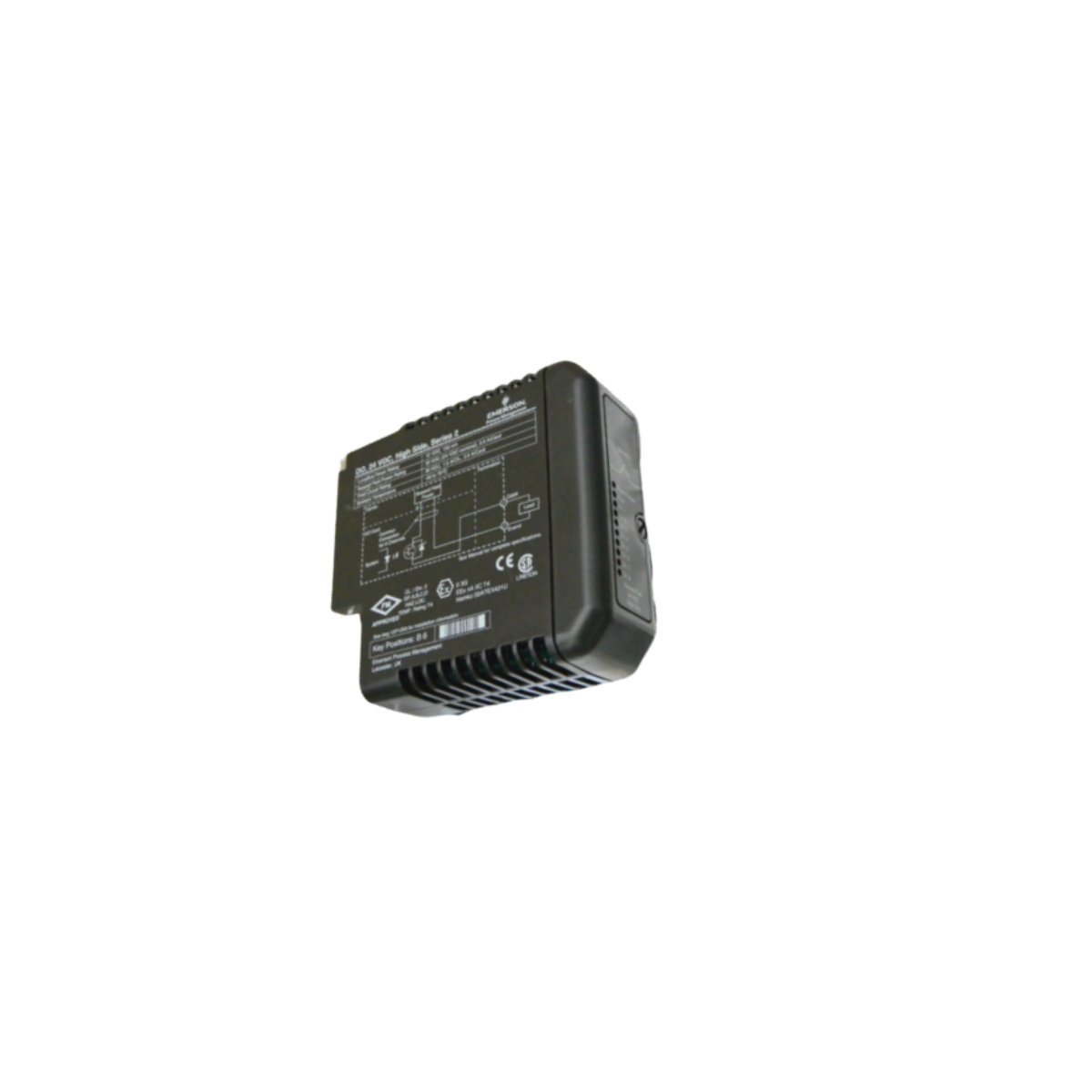
GE Multilin UR8GH Universal Relay Voltage Transformer (VT) Module
Sale!
SKU: UR8GH
GE Multilin UR8GH Universal Relay Voltage Transformer (VT) Module
The GE Multilin UR8GH is a high-precision Voltage Transformer (VT) module designed for the Universal Relay (UR) series. This 0.36kg digital I/O module provides accurate secondary signal processing for CT/VT devices, enabling real-time monitoring, fault detection, and robust protection in utility substations and complex industrial power systems.
The GE UR8GH serves as a specialized Voltage Transformer (VT) and Current Transformer (CT) interface module designed exclusively for the GE Multilin Universal Relay (UR) series. This high-performance digital module functions as the critical sensory gateway for protective relays, converting high-voltage primary signals into precise digital data for the relay’s central processing unit. By providing accurate secondary voltage and current measurements, the UR8GH enables advanced protection, monitoring, and control strategies across utility and industrial power networks.
Technical Specifications
Manufacturer:Â General Electric (GE)
Product Line:Â Multilin Universal Relay (UR) Series
System Integration:Â Multilin G60, C60, L90, and other UR-platform relays
Net Weight:Â 0.36 kg
Module Dimensions:Â 8.2 cm x 12.2 cm x 6.0 cm
Core Functionality and Technical Characteristics
The UR8GH module facilitates seamless communication between physical power apparatus and digital protection logic. It captures analog waveforms from field transformers and digitizes them with high resolution to ensure relay precision during fault conditions.
Key technical advantages include:
High-Precision Data Acquisition:Â The module employs advanced sampling techniques to provide real-time data for fault detection, metering, and power quality analysis.
Multi-Channel Versatility:Â It supports multiple input channels, allowing for the simultaneous monitoring of three-phase voltages and currents required for complex protection schemes.
Ruggedized Industrial Interface:Â Engineered to operate within the high electromagnetic interference (EMI) environments of power substations and industrial plants.
Integrated Protection Logic Support:Â The UR8GH provides the essential data stream required for differential protection, overcurrent detection, and voltage-controlled automation.
Enhanced System Diagnostics:Â Continuous self-monitoring ensures the module detects internal circuitry failures or signal loss, triggering alarms to prevent protective “blind spots.”
Primary Industrial Applications
The GE UR8GH VT Module is a staple in high-reliability power infrastructure and heavy industry:
Power Generation:Â Monitoring voltage and current levels in thermal, hydroelectric, nuclear, and wind power facilities.
Substation Automation:Â Serving as the measurement interface for transmission and distribution grid protection.
Industrial Manufacturing:Â Providing power system stability for chemical processing, automotive assembly, and steel mills.
Renewable Energy:Â Integrating wind and solar farm outputs into the main grid with precise frequency and voltage synchronization.
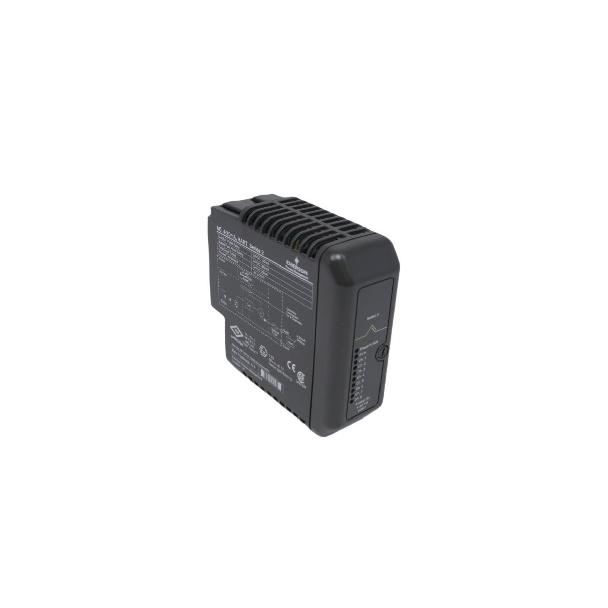
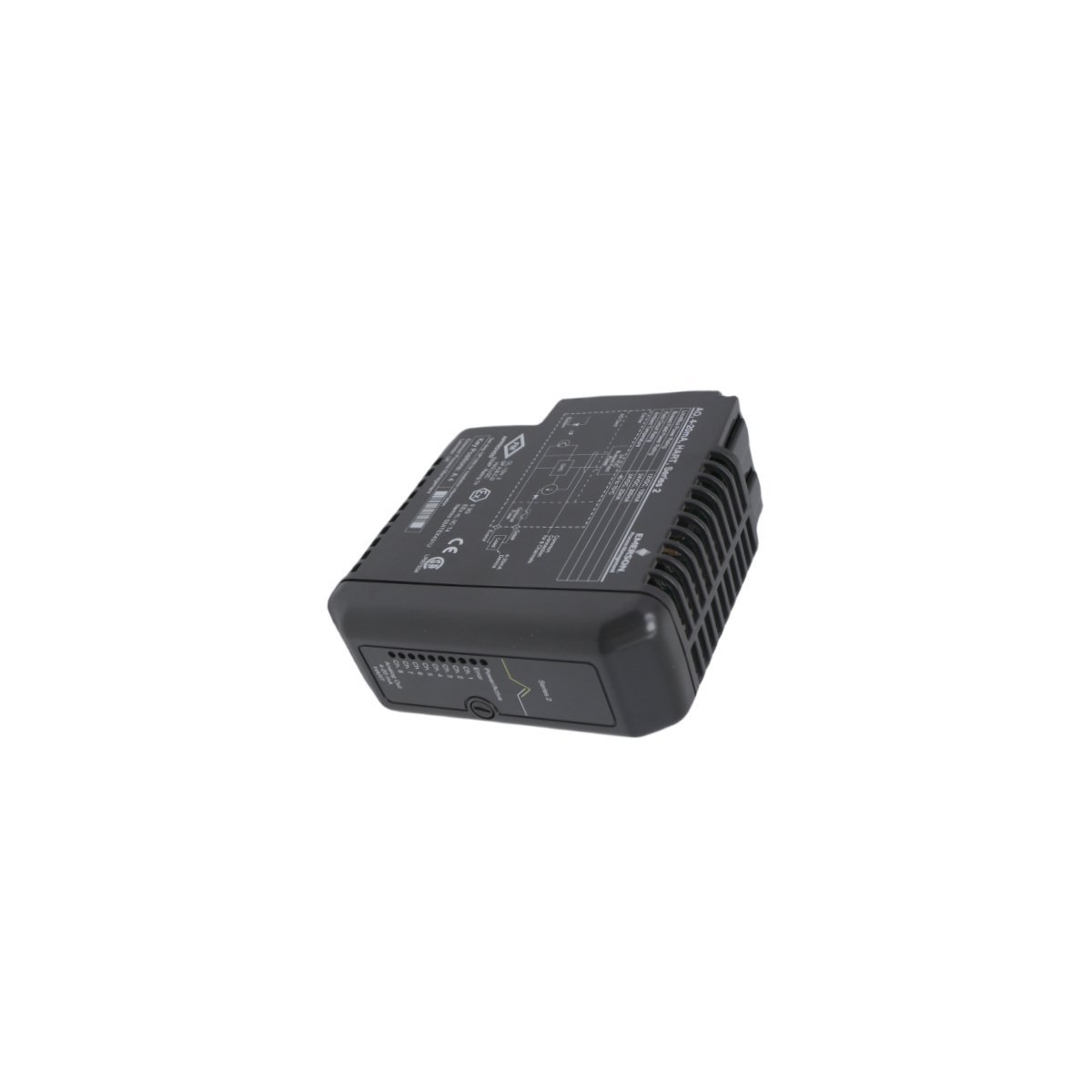
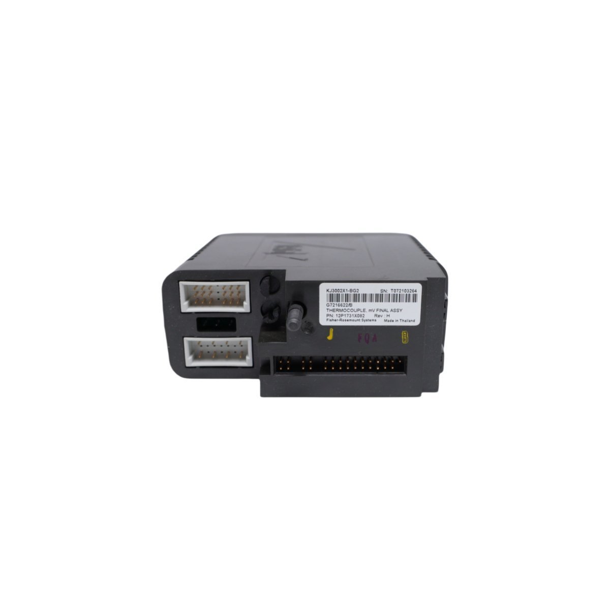
Configured for direct analog signal acquisition in Emerson DeltaV DCS environments, the Emerson KJ3002X1-BG2, also cataloged as the KJ3002X1-BG2 Thermocouple Module, provides direct physical/electrical execution.
Hardware Specifications
Parameter
Specification
Model
KJ3002X1-BG2
Brand
Emerson
Part Number
12P1731X022
System Reference
VE4003S5B1
Range of Product
DeltaV M-series I/O Subsystem
Module Type
Thermocouple Module
Channels
8 Channels
Origin
USA
Weight
0.2 kg
Dimensions
8.1 x 7.9 x 8.8 cm
HS Code
8537101190
Status
Discontinued (Dec 31, 2018)
Process Control and DCS Characteristics
Converts millivolt inputs from field thermocouples into digitized temperature values for system controller processing.
Features integrated cold junction compensation (CJC) algorithms to maintain signal accuracy across varying cabinet temperatures.
Utilizes channel-to-channel isolation architecture to eliminate ground loops and reject common-mode voltage spikes across industrial field cabling.
Incorporates 4-20 mA HART loop protocol carrier compatibility across system backplane interfaces for extended instrument diagnostic passthrough.
Frequently Asked Questions
Q: How does the KJ3002X1-BG2 module perform cold junction compensation?A: Cold junction compensation is maintained via internal thermal sensors embedded on the terminal block assembly, correcting for ambient variations at the wiring termination point.Q: Can the module be inserted or removed while the terminal base is powered?A: Yes, DeltaV M-series I/O modules support power-on insertion and removal (removal under power) when installed on compatible I/O carrier bases.
Field Installation Guidelines
Secure the module onto the DeltaV M-series I/O carrier until the locking mechanisms fully engage with the backplane base.
Ensure shielded thermocouple wiring is grounded at a single point to prevent high-frequency noise interference on low-millivolt input channels.
Maintain a minimum bending clearance for field wiring to prevent mechanical stress on terminal connectors.
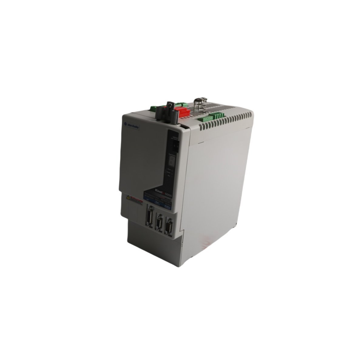
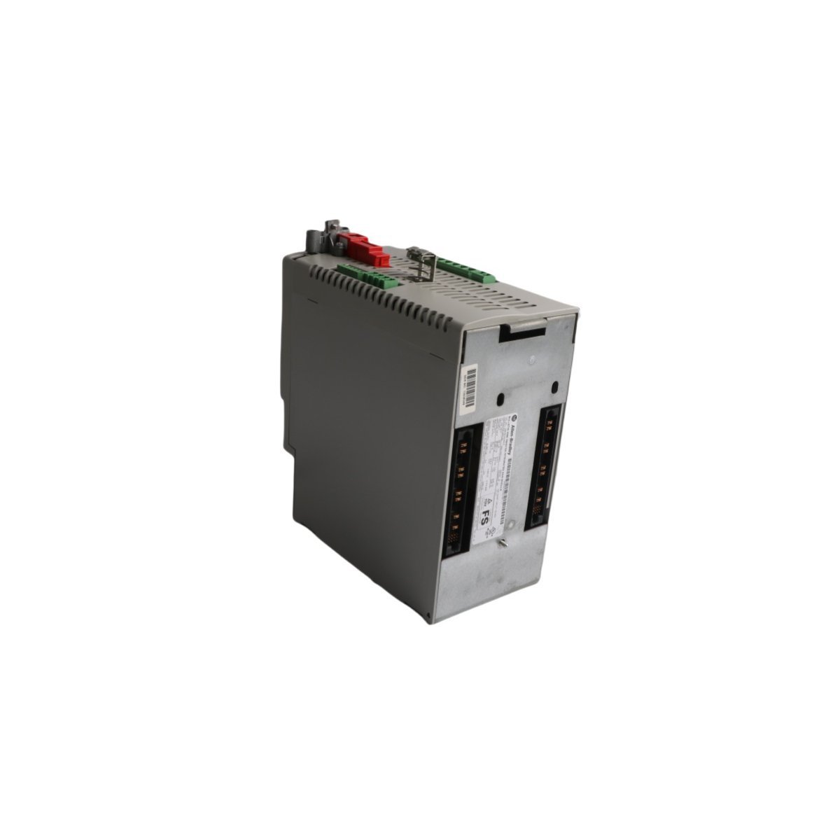
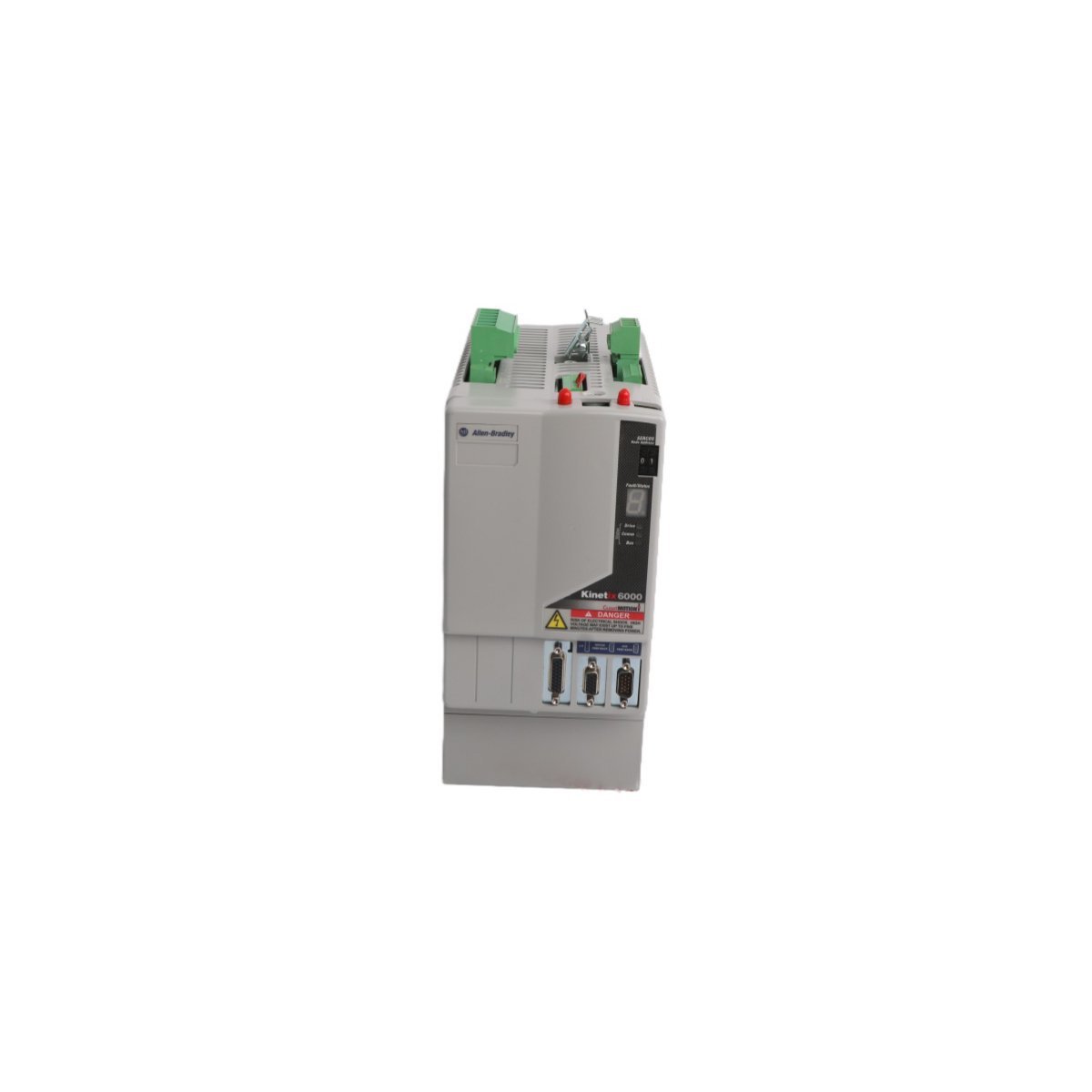
The Allen-Bradley 2094-BC02-M02-M, also cataloged as the 2094-BC02 Integrated Axis Module, operates as a dedicated hardware component for AC line power rectification and axis motion execution within Kinetix 6000 multi-axis servo systems. It converts three-phase AC input voltage into a regulated DC bus supply while simultaneously controlling a single servo axis inverter output. The module features embedded hardware-based Safe Torque-Off (STO) logic, solid-state motor short-circuit monitoring, and direct interface links for multi-axis power sharing across external drive rails.
Hardware Specifications
Parameter
Specification
Model
2094-BC02-M02-M
Brand
Allen-Bradley
Origin
USA
Module Type
Integrated Axis Module (IAM)
System Architecture
PLC / Kinetix 6000 Multi-Axis Servo
Input Voltage Range
360-480 VAC, 3-Phase
Converter Power Rating
15 kW / 23 A
Inverter Power Rating
6.6 kW / 14.6 A
Heat Dissipation
44 W (Converter), 72 W (Inverter)
Short Circuit Rating
200000 A (Fused), 65000 A (Circuit Breaker)
Integrated Safety
Safe Torque-Off (STO)
Control Input Fuse Recommendation
Bussmann FNQ-R-10 (10 A)
DC Bus Power Fuse Recommendation
Bussmann FWJ-40A
HS Code
8537101190
Dimensions
12.7 cm x 29.2 cm x 25.4 cm
Weight
5.6 kg
Operating Temp
0 to 50 deg C
EtherNet/IP and SERCOS Deterministic Network Integration
The module coordinates real-time synchronization using EtherNet/IP and SERCOS communication interfaces. High-speed position and velocity loop data flow deterministically between the central Logix controller and the drive inverter stages over cyclic network slots. Internal timing hardware synchronizes multi-axis motion cycles to reduce axis skew. Integrated diagnostic registers transmit voltage levels, thermal status, phase loss detections, and motor fault flags back to the controller without dedicated external sensor wiring.
Frequently Asked Questions
Q: What branch circuit protection fuses are mandated for input power isolation?A: Control input power loops require Bussmann FNQ-R-10 (10 A) fuses, while the DC bus power link requires Bussmann FWJ-40A fuses to achieve a 200000 A short-circuit current rating (SCCR).Q: How does the integrated Safe Torque-Off (STO) function operate electronically?A: The STO circuit directly disables the gate drive signals to the output power transistors (IGBTs), preventing the inverter from generating motor torque without removing main line input power from the power supply stage.Q: What are the thermal dissipation metrics during partial load operations?A: Under standard partial load conditions, the internal converter section dissipates 44 W of heat, and the internal inverter section dissipates 72 W of heat into the cabinet enclosure.
Field Installation Guidelines
Enclosure Clearance and Thermal Mounting: Mount the module vertically on a flat, grounded surface inside an IP54 or NEMA 12 industrial enclosure. Maintain a minimum vertical clearance of 50 mm above and below the chassis to allow unimpeded convection airflow through the heat sink assembly.
Grounding and Shielding Protocols: Connect the module ground lug directly to the central enclosure ground bus using a low-impedance stranded copper conductor. Motor power cables must utilize 360-degree continuous metallic braid shielding clamped directly to the chassis ground plate to suppress high-frequency electromagnetic interference (EMI).
Power and DC Bus Terminal Wiring: Ensure three-phase 360-480 VAC line power is disconnected before accessing input terminal blocks. Verify correct terminal polarity on shared DC bus link bars when interconnecting additional follower axis modules on the power rail. Torque all power terminal screw connections to the vendor-specified mechanical limits.
The Allen Bradley 80190-560-01-R, also cataloged as the 80190-560-01-R PC Board, operates as a dedicated hardware component for industrial communication and signal routing within PLC networks.
Hardware Specifications
Parameter
Specification
Model
80190-560-01-R
Brand
Allen Bradley
Origin
USA
Weight
0.4 kg
Dimensions
19.1 x 18.8 x 6.5 cm
Operating Temp
Industrial Standard
Power Consumption
System Backplane Dependent
Primary Function
Ethernet Router / Signal Processing
Profinet and EtherNet/IP Deterministic Network Characteristics
The 80190-560-01-R leverages integrated logic to facilitate deterministic data exchange across industrial networks. Specifically, the module supports high-speed packet routing, thereby minimizing latency in Ethernet-based PLC backplane communication. Furthermore, firmware flash compatibility ensures the hardware remains synchronized with contemporary network protocols. In addition to this, I/O density scaling allows for seamless integration into complex, multi-node automation environments without compromising bus velocity. Consequently, the system maintains strict timing compliance even as network traffic demands increase.
Frequently Asked Questions
Q: Does the 80190-560-01-R support live extraction from the PLC backplane?A: No. Power must be disconnected from the chassis before installing or removing the PC Board to prevent electrical arcing or damage to backplane pin connectors.Q: How should the module be configured for network routing?A: Configuration is performed via the primary PLC programming environment, utilizing the integrated Ethernet router interface to map physical addresses to logical network tags.
Field Installation Guidelines
Ensure the control cabinet power is isolated and locked out before installation.
Inspect the PCB edge connectors for any oxidation or mechanical deformation.
Slide the module into the designated PLC chassis slot, ensuring the backplane connector aligns correctly with the receiving socket.
Secure the module using the top and bottom captive screws to ensure proper grounding and mechanical stability on the DIN rail.
Connect shielded Ethernet cabling to the designated ports, ensuring the cable shield is terminated at the cabinet common ground point to minimize EMI interference.
The Allen Bradley 81001-450-52-R Power Block Drive, also cataloged as the 81001-450-52-R Power Block Drive, operates as a dedicated hardware component for power distribution and conversion within PLC platform networks.
Hardware Specifications
Parameter
Specification
Model
81001-450-52-R
Brand
Allen Bradley
Origin
USA
Weight
1.14 kg
Dimensions
25 x 20.7 x 5.5 cm
Operating Temp
Standard Industrial Range
Power Consumption
System Dependent
Module Type
Power Block Drive
PLC Deterministic Network Integration
The Allen Bradley 81001-450-52-R utilizes backplane bus communication protocols designed for integration with PLC control architectures. The module supports deterministic network timing, ensuring low-latency power state feedback and synchronization within complex I/O density configurations. Compatibility with field-programmable firmware allows for flash updates to align with evolving backplane bus communication velocity requirements, maintaining bus traffic integrity and reducing collision potential in high-speed control loops.
Frequently Asked Questions
Q: What are the restrictions regarding the installation of the 81001-450-52-R in a redundant power rack?A: Ensure that the backplane bus address is correctly configured to prevent signal collisions. Redundant power configurations must be verified for voltage matching before closing the primary disconnect.Q: Is this module capable of firmware field-upgrades?A: Yes, the unit supports firmware flash compatibility via the primary control bus. Consult the PLC backplane interface documentation for current revision requirements.
Field Installation Guidelines
Mount the module onto a standard metal DIN-rail. Ensure the rail is bonded to the cabinet chassis ground to minimize EMI.
Maintain a minimum clearance of 50 mm above and below the unit to allow for passive thermal heat dissipation.
All power input cabling must utilize shielded twisted-pair conductors to prevent common-mode noise injection into the PLC backplane.
Verify that the 24 VDC output load does not exceed the continuous current rating specified for the associated PLC power bus segment.
Ensure the connector interface is fully seated until a tactile lock is achieved to prevent intermittent contact resistance.
The Allen Bradley 80190-378-51, also cataloged as the 80190-378-51 PC Board, operates as a dedicated hardware component for signal processing and logic execution within PLC-5 platform networks.
Hardware Specifications
Parameter
Specification
Model
80190-378-51
Brand
Allen Bradley
Origin
USA
Weight
0.46 kg
Dimensions
27.8 x 21.4 x 2.8 cm
Operating Temp
Standard Industrial Range
Power Consumption
System Dependent
Module Type
PC Board
PLC Deterministic Network Integration
The Allen Bradley 80190-378-51 utilizes backplane bus communication protocols designed for integration with PLC-5 control architectures. The module supports deterministic network timing, ensuring low-latency state feedback and synchronization within complex I/O density configurations. Compatibility with field-programmable firmware allows for flash updates to align with evolving backplane bus communication velocity requirements, maintaining bus traffic integrity and reducing collision potential in high-speed control loops.
Frequently Asked Questions
Q: What are the restrictions regarding the installation of the 80190-378-51 in an active PLC-5 backplane?A: Ensure that the backplane power is cycled off before insertion or removal to prevent electrical arcing on the connector pins. The module must be correctly seated in the chassis slot to maintain signal integrity across the backplane bus.Q: Is this module capable of firmware field-upgrades?A: Yes, the unit supports firmware flash compatibility via the primary control bus interface. Verify the current revision against the specific PLC-5 processor requirements before initiating any update sequence.
Field Installation Guidelines
Mount the PC Board into a standard PLC-5 chassis. Ensure the mounting screws are tightened to the specified torque to guarantee a secure electrical chassis ground connection.
Avoid exposing the component to electrostatic discharge (ESD). Utilize a grounded wrist strap when handling the board.
Ensure all backplane pins are free of debris or oxidation before installation.
Maintain ambient operating temperature within the specified industrial limits to prevent thermal degradation of on-board components.
Verify that the backplane power supply capacity is sufficient for the total I/O density load when the module is initialized.
Configured for signal distribution in DeltaV M-series I/O subsystems, the Emerson KJ3222X1-BA1 (KJ3222X1-BA1 Redundant Terminal Block) provides direct physical and electrical execution of field wiring termination for redundant I/O configurations.
Hardware Specifications
Parameter
Specification
Model
KJ3222X1-BA1
Brand
Emerson
Origin
USA
Weight
0.2 kg
Dimensions
4.1 x 12.5 x 10.5 cm
Operating Temp
Standard Industrial Range
Power Consumption
Passive Component
Compatibility
DeltaV M-series I/O
DeltaV DCS Process Control Characteristics
The terminal block facilitates the implementation of 4-20 mA HART loop protocol architectures by providing physical connection points for redundant I/O card pairs. It maintains channel-to-channel isolation through optimized PCB routing, preventing cross-talk between high-density loops. The mechanical design ensures cold junction compensation (CJC) stability when integrated with thermocouple input channels. By utilizing the redundant terminal architecture, the system maintains continuous signal integrity for critical control loops, allowing for maintenance operations on one I/O module without disrupting the current loop of the secondary redundant partner.
Frequently Asked Questions
Q: Does the KJ3222X1-BA1 support active electronic components?A: No, this is a passive terminal block. It serves as an interface between field wiring and the DeltaV I/O carrier, routing signals to the redundant I/O module pair.Q: Can this terminal block be used for non-redundant I/O configurations?A: While designed for redundancy, the terminal block provides the physical interface required for specific DeltaV M-series modules. Compatibility must be verified against the specific I/O module part number (VE4033S2B1) to ensure pin mapping alignment.
Field Installation Guidelines
Prior to wiring, verify that the I/O carrier power is disconnected to prevent accidental contact with energized field circuits.
During installation, align the terminal block with the mating connectors on the DeltaV I/O carrier, ensuring the guide pins are fully seated before tightening the retention screws.
When connecting field devices, ensure that shielded, twisted-pair cabling is utilized for all 4-20 mA loops to mitigate electromagnetic interference.
Upon securing the wiring, verify the continuity of the redundant paths using a digital multimeter at the terminal points before initiating loop commissioning.
Maintain appropriate physical separation between the terminal block wiring and any high-voltage AC lines to prevent induced noise on the analog signal loops.
The Allen-Bradley 2094-BC01-M01-S, also cataloged as the 2094-BC01-M01-S Integrated Axis Module, operates as a dedicated hardware component for high-speed motion control and power regulation within Kinetix 6000 multi-axis drive platforms.
Hardware Specifications
Parameter
Specification
Model
2094-BC01-M01-S
Brand
Allen-Bradley
Origin
USA
Weight
0.9 kg
Dimensions
3.5 cm x 13 cm x 14.5 cm
Operating Temp
Standard industrial range
Power Consumption
3.9 kW (Total)
Inverter Current
9 A
Input Voltage
360-480 V AC
PLC and Drive Control Characteristics
The 2094-BC01-M01-S incorporates backplane bus communication velocity protocols, enabling deterministic synchronization between the converter and inverter stages. The architecture facilitates I/O density scaling within the drive cabinet, allowing for coordinated power distribution across multiple integrated axes. Furthermore, the module supports firmware flash compatibility, which ensures that internal logic remains aligned with system-wide motion control requirements. This design enables precise control over power threshold excursions and maintains stable torque output during transient loading conditions.
Frequently Asked Questions (FAQ)
Q: What are the primary communication requirements for the SERCOS interface on this module?A: The SERCOS interface requires fiber optic media configured in either linear or ring topologies; ensure that the fiber ends are polished and properly seated in the transceivers to maintain signal integrity and avoid communication latency.Q: Can the Safe Torque Off (STO) function be bypassed if not required by the application?A: The STO circuit must remain closed via the designated safety input terminals to enable drive operation; if the safety function is not utilized, you must jumper these inputs according to the installation manual to permit the pulse-width modulation (PWM) output to the motor.
Field Installation Guidelines
To begin with, ensure all primary power is disconnected and the DC bus capacitors have reached a discharge state before you mount the module onto the power rail;Â subsequently, verify that the rear-facing power connectors align correctly to prevent pin deformation.
Furthermore, terminate all motor feedback cables using the appropriate shielded connectors;Â in addition, ensure the shield drain wire connects to the designated ground lug to minimize electromagnetic interference (EMI).
When configuring the SERCOS ring, route fiber optic cables with a sufficient bend radius to prevent signal attenuation;Â meanwhile, label each fiber connection to identify the transmit (Tx) and receive (Rx) paths clearly.
Finally, verify the input voltage range (360-480 V AC) matches the site supply before you apply power;Â by doing so, you ensure the internal power conversion stage functions within rated limits.
The GE DS200TCEAG1BTF is a dedicated Emergency Overspeed Board for the Mark V turbine control system. It features an integrated microprocessor and hardware-based protection to monitor turbine velocity and execute critical safety trip functions reliably.
The Allen Bradley 80190-440-02-R interface board provides reliable signal management and logic control for SMC Flex soft starter motor protection systems.
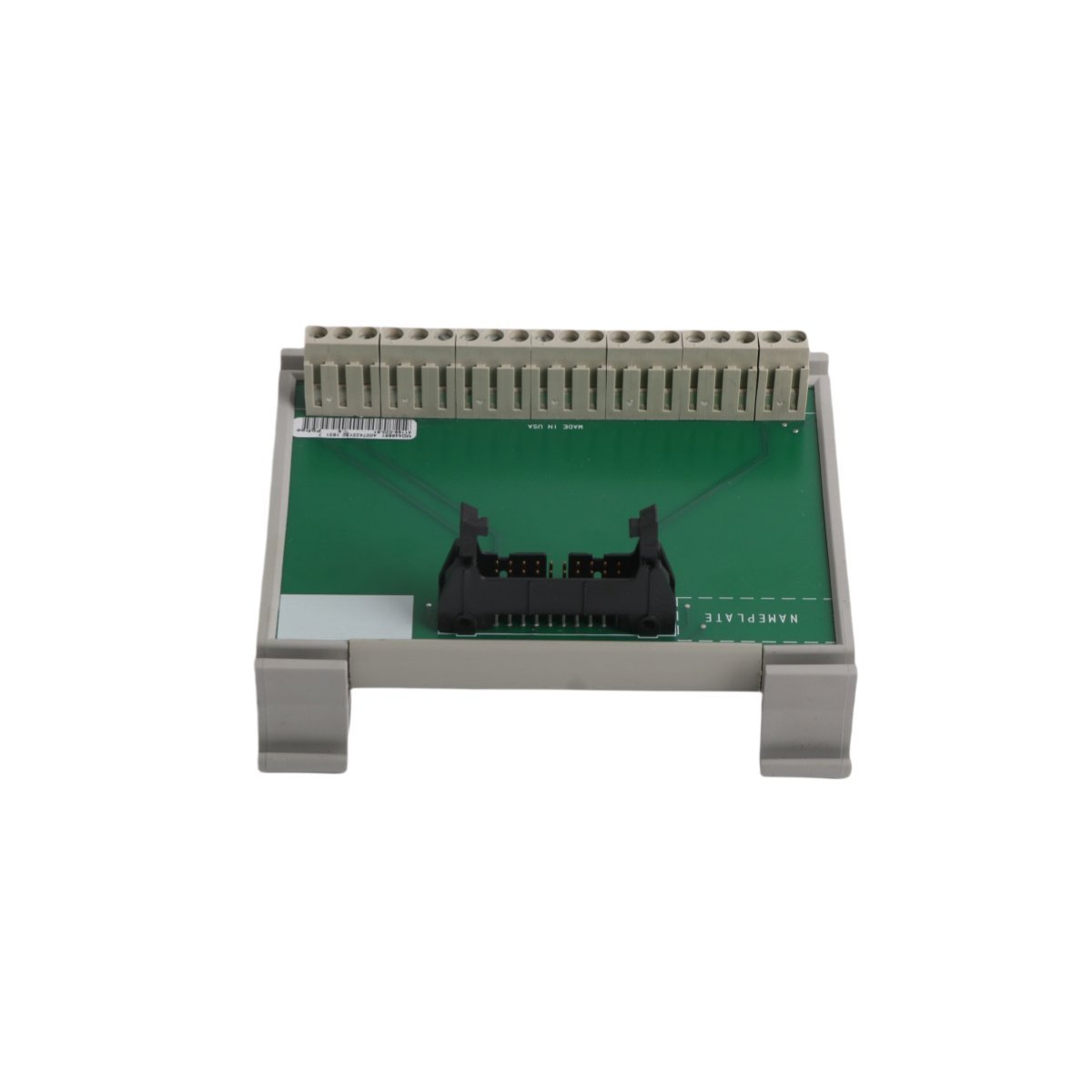
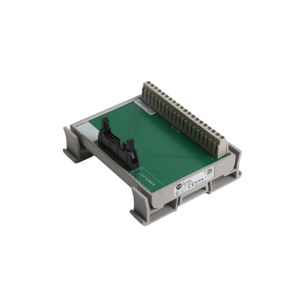
The Allen-Bradley 1492-IFM20F-F120A-2 is a 20-point fusible termination module featuring 120V AC/DC blown-fuse indicators and group isolation. It provides robust circuit protection and simplified field wiring for industrial PLC systems.
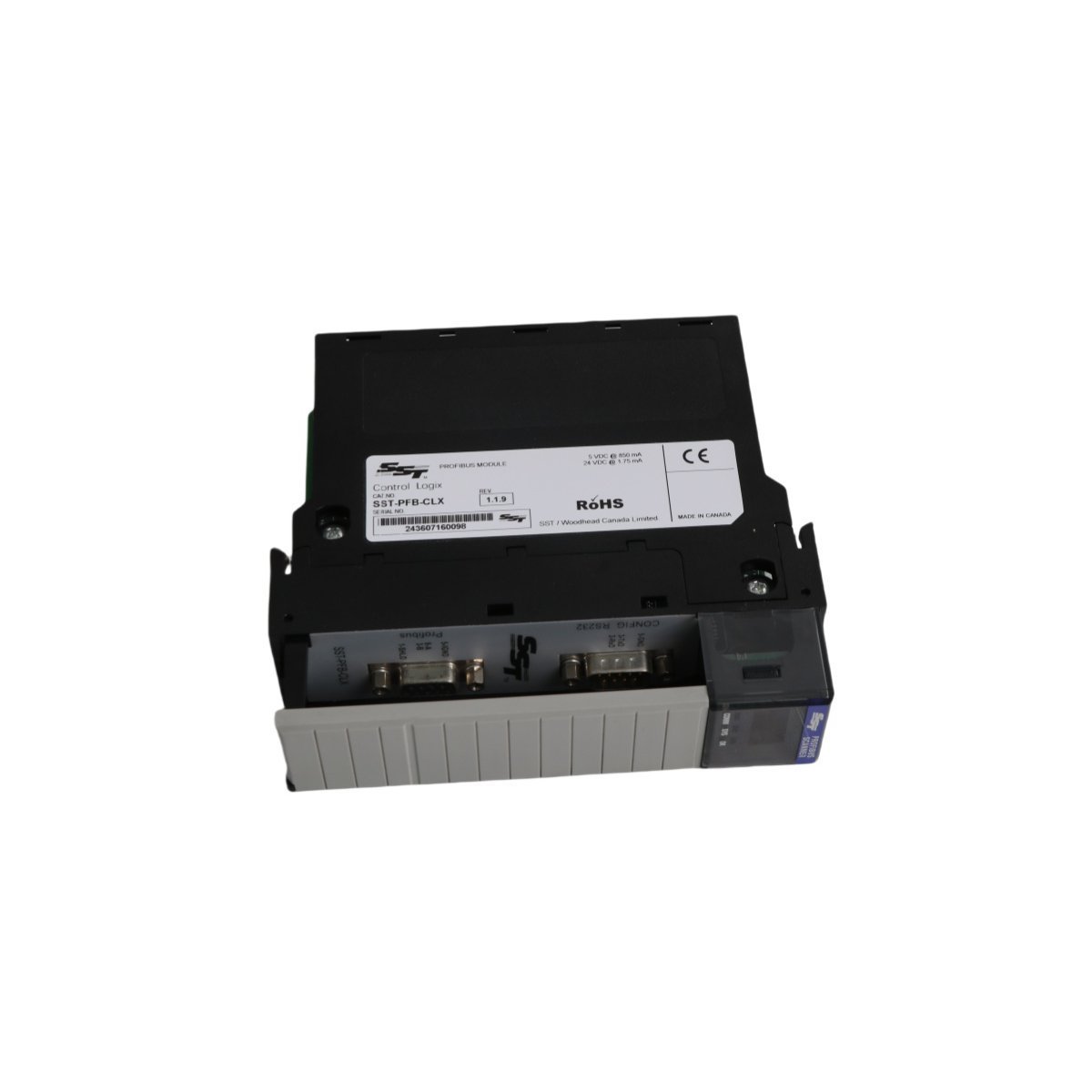
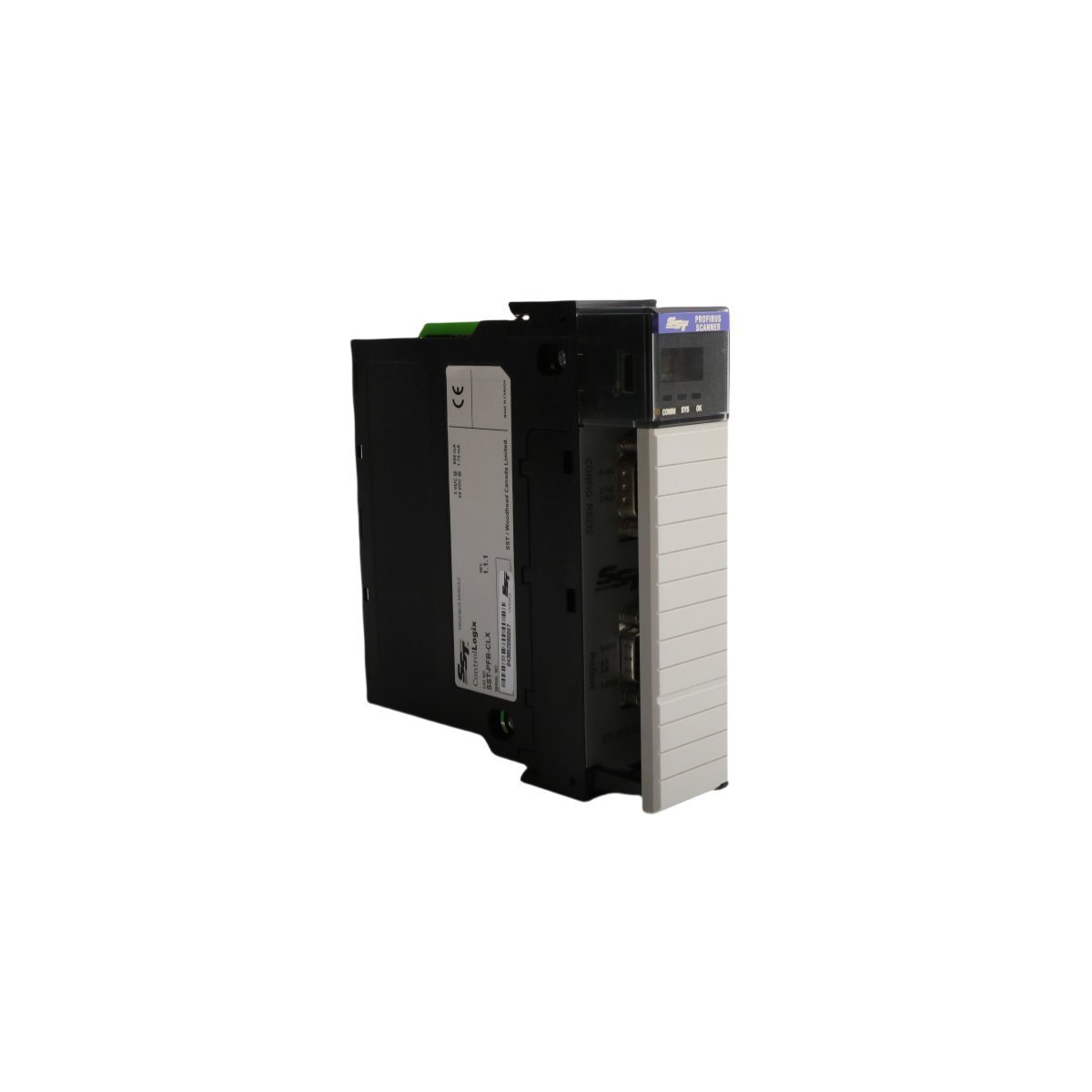
The Allen-Bradley SST-PFB-CLX is a ControlLogix PROFIBUS DP Master Scanner module that provides seamless integration between Rockwell controllers and PROFIBUS networks. It supports up to 12 Mbps data rates and features a dedicated configuration port for easy system setup.
The GE Fanuc IC670CHS002 is a high-performance terminal block for Field Control systems. It features isolated common groups (A, B, and E) for flexible power distribution and a modular design that allows for I/O module replacement without disconnecting field wiring.
We are committed to protecting your privacy. The information collected here is strictly used to provide the requested quotes, technical support, and relevant industrial automation solutions.