


Sale!
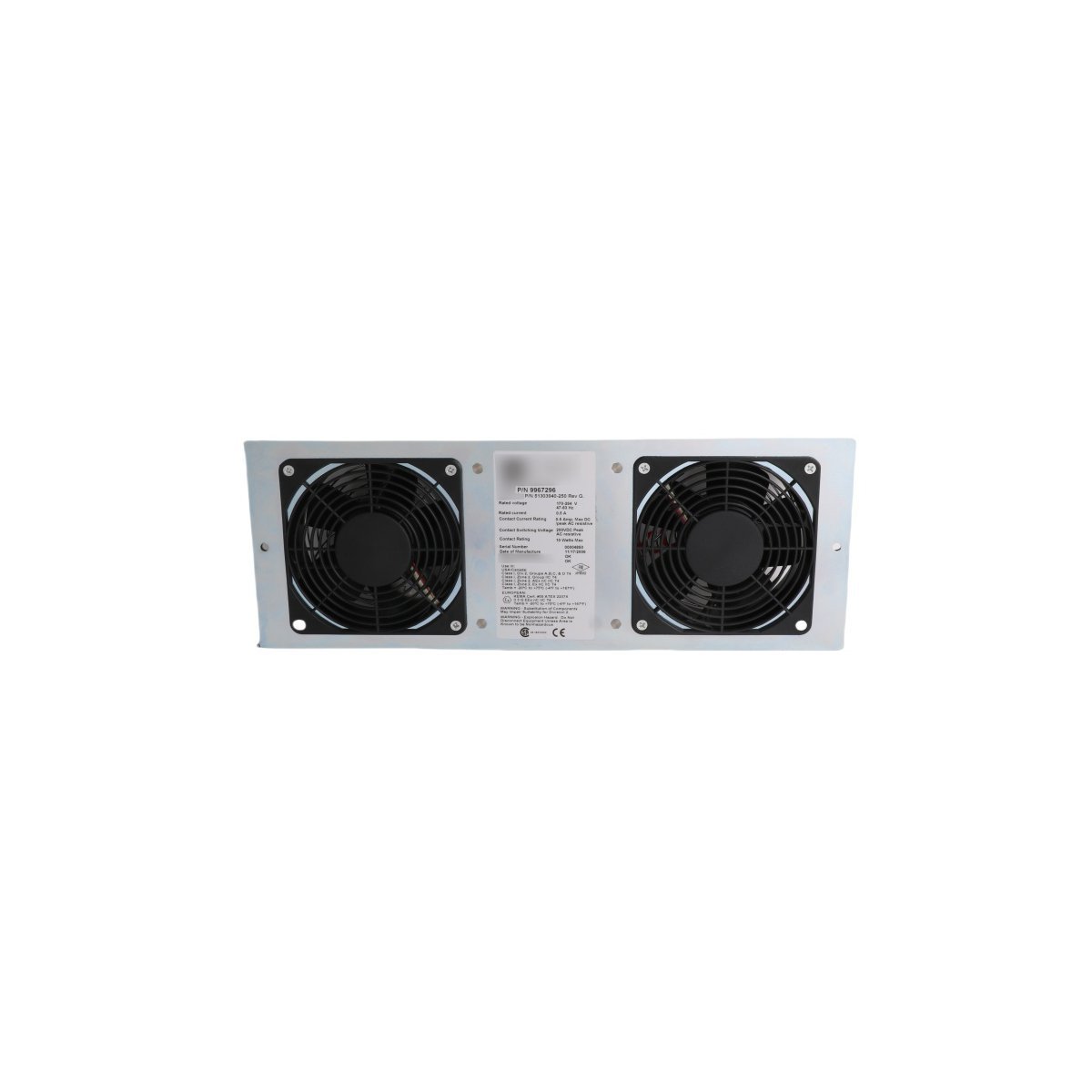
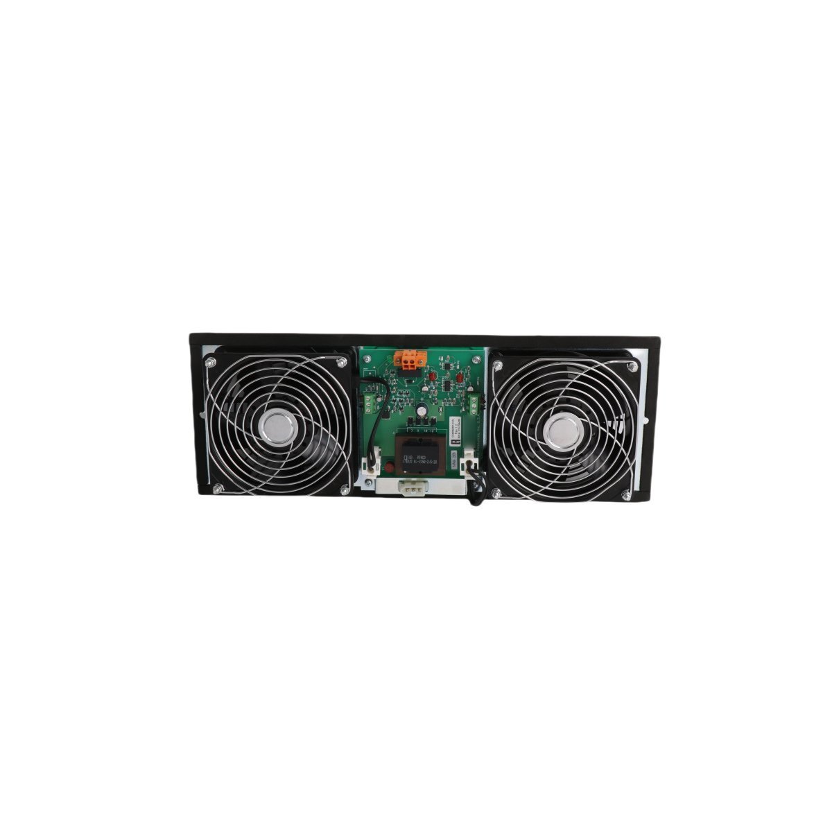
Honeywell 51303940-250 TDC 3000 Series Cabinet Fan With Alarm
Honeywell 51303940-250 cooling fan assembly with integrated alarm for TDC 3000 cabinets. Brand New, Original Stock, Global Shipping. Full specifications detailed.
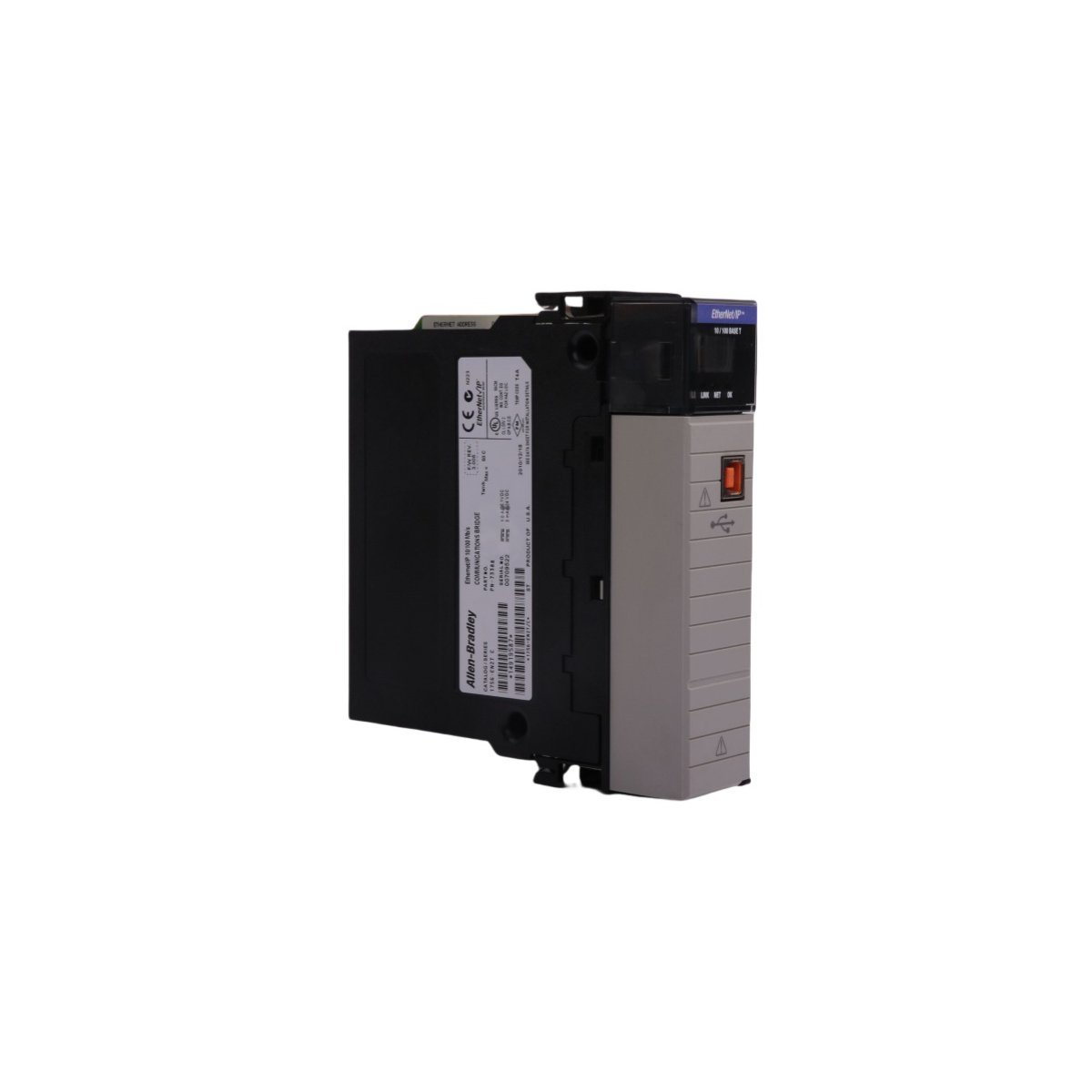
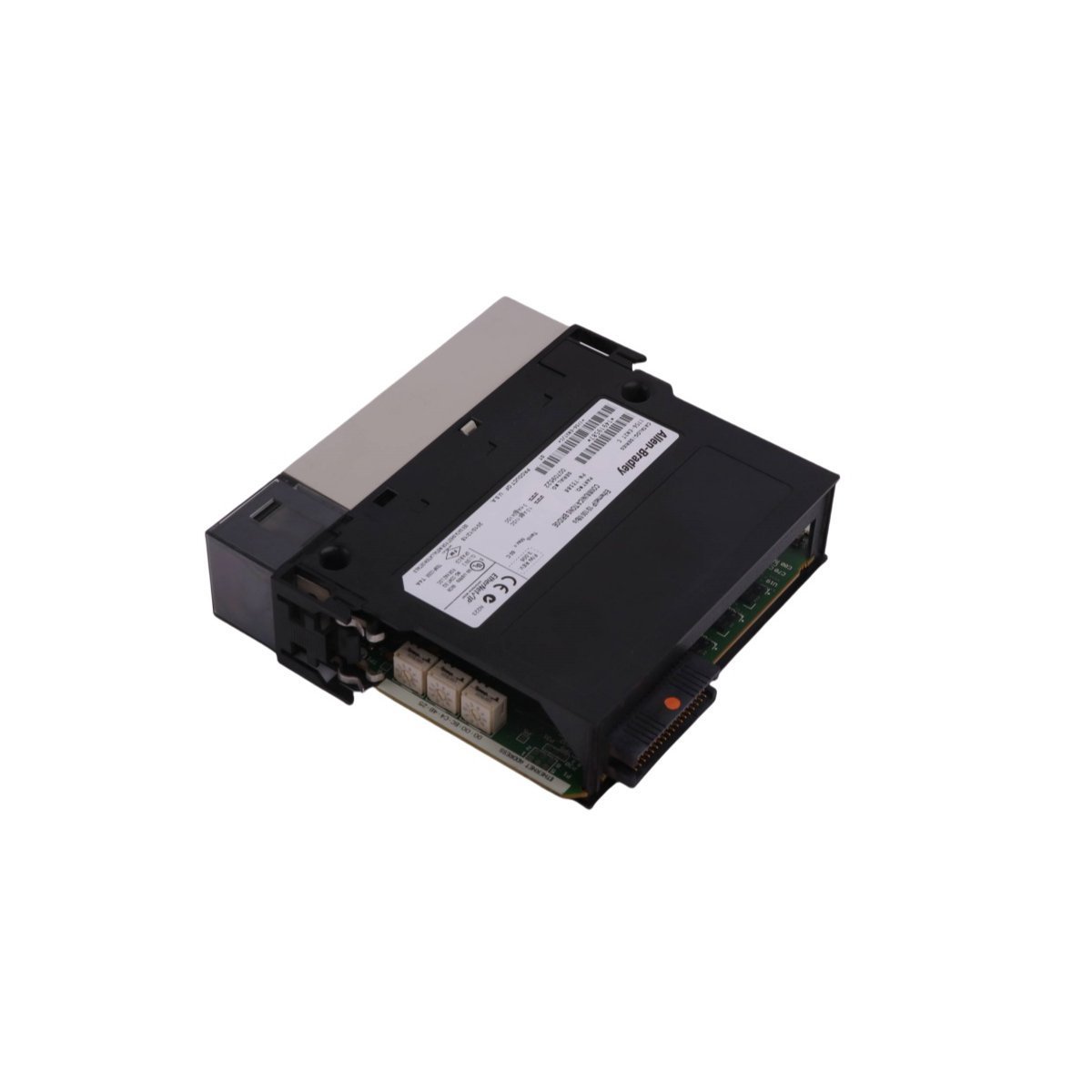
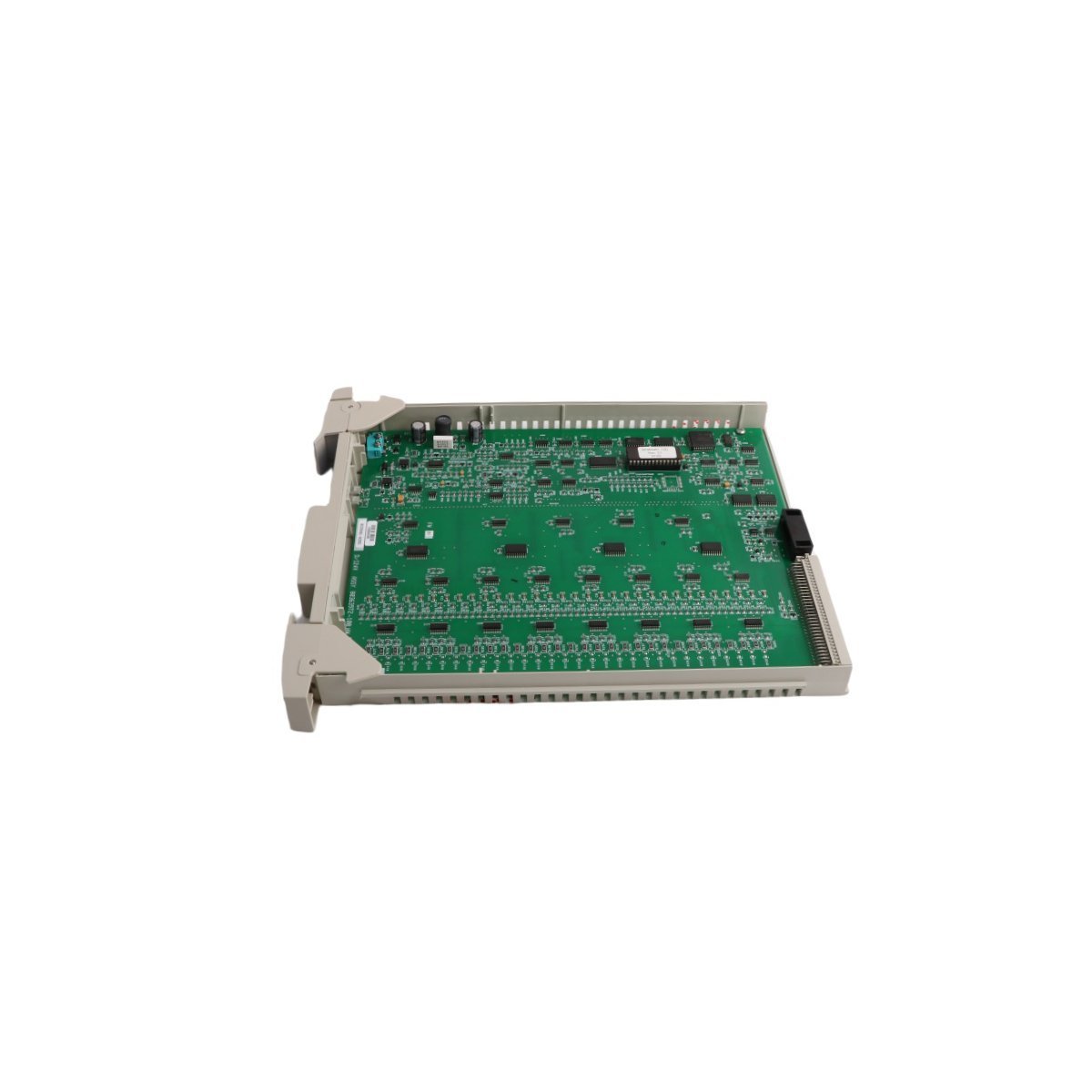
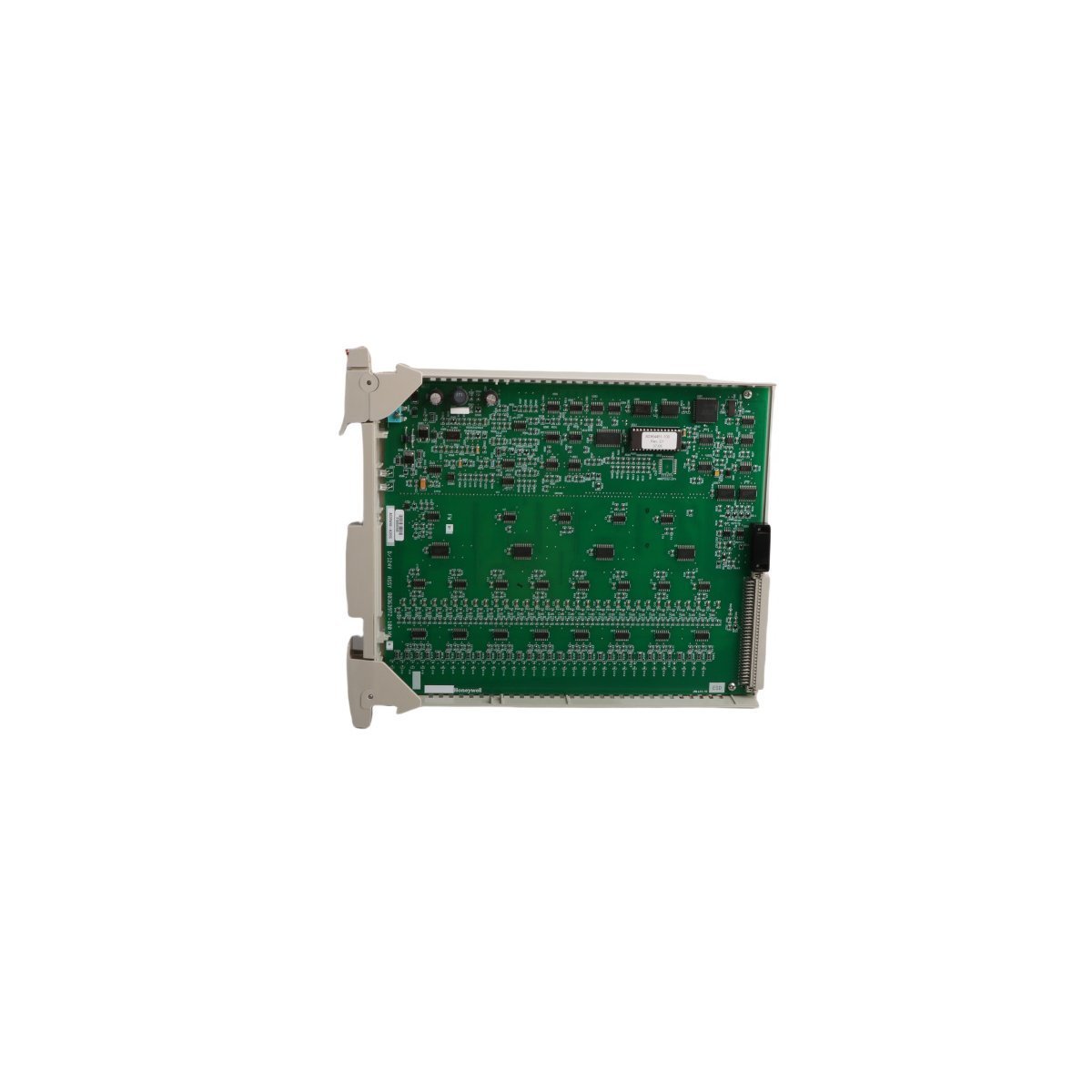
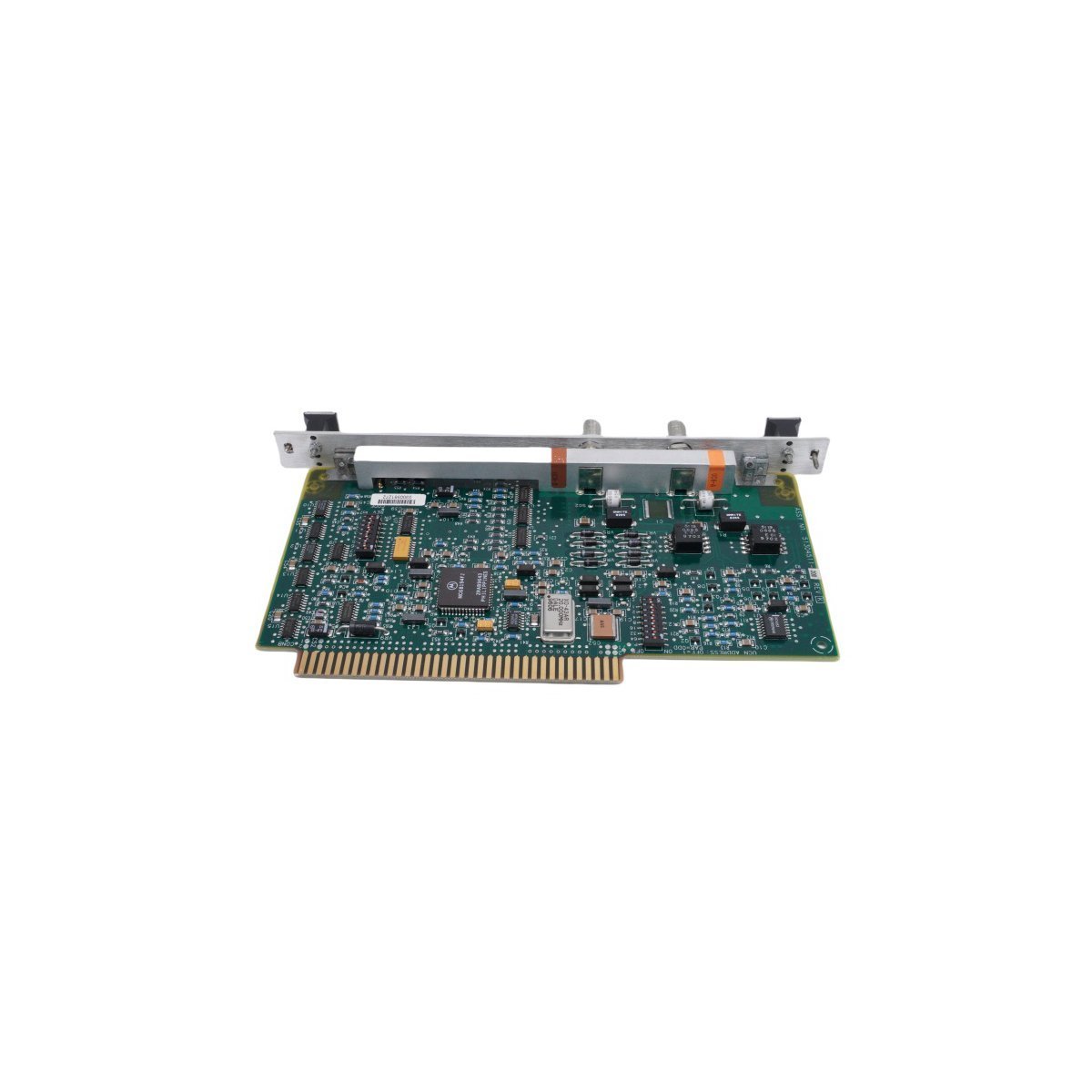
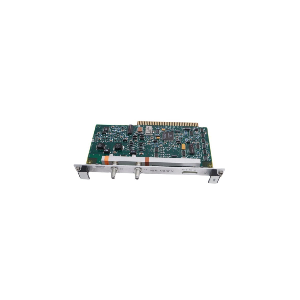
Configured for signal distribution and UCN communication management in TDC 3000 system architectures, the Honeywell 51304511-100 (51304511-100 Network Interface Module) provides direct physical/electrical execution for data routing between control nodes.
| Parameter | Specification |
|---|---|
| Model | 51304511-100 |
| Brand | Honeywell |
| Origin | USA |
| Weight | 0.24 kg |
| Dimensions | 2 x 13.3 x 23.7 cm |
| Operating Temp | Standard Industrial |
| Power Consumption | Not Specified |
| Module Type | Network Interface Module |
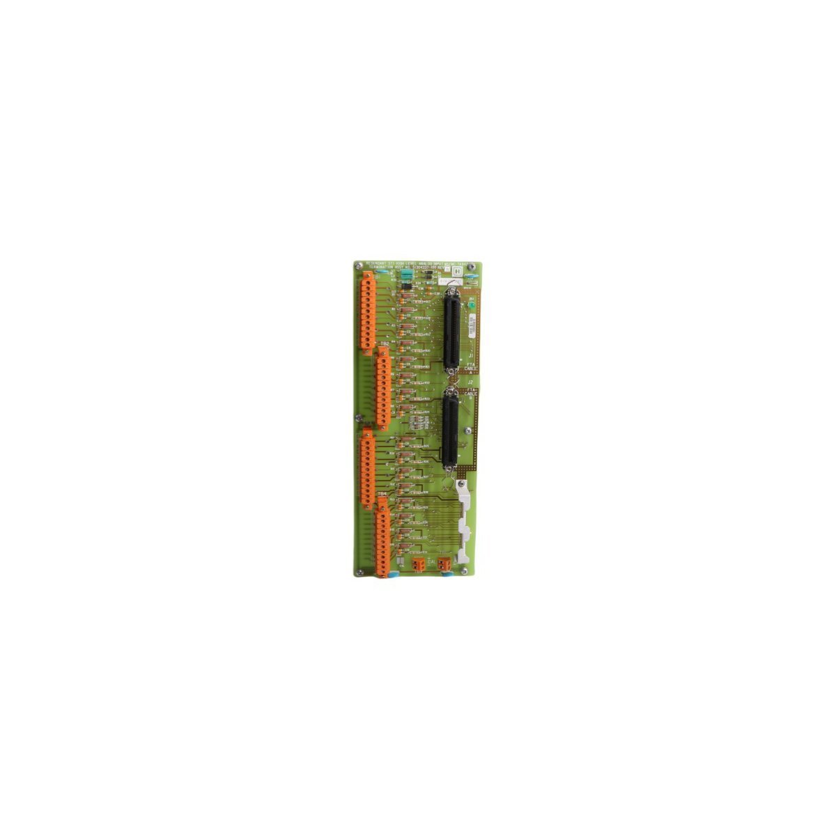
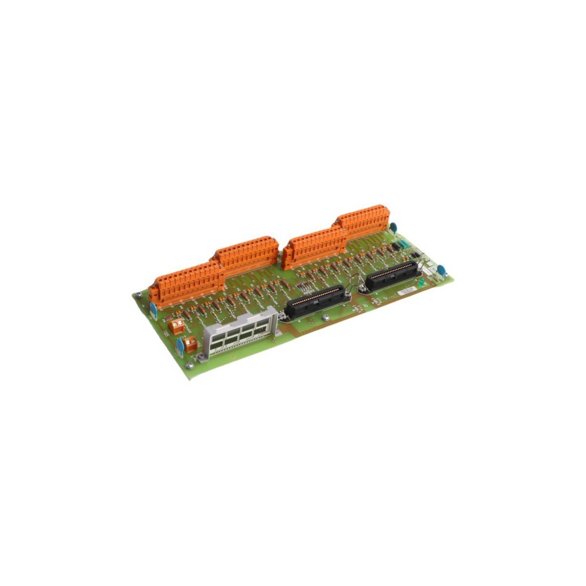
Signal integrity is primarily maintained within the DCS environment through the systematic implementation of dedicated input termination pathways. Consequently, data acquisition is facilitated by the 51304511-100, whereby field sensor signals are processed and subsequently routed to the control cabinet backplane. Furthermore, channel-to-channel isolation is consistently utilized so that, as a result, common-mode noise propagation is effectively prevented. In this manner, it is ensured that 4-20 mA HART loop protocol signals or discrete inputs are accurately translated. Additionally, cold junction compensation (CJC) is managed via the associated termination logic; meanwhile, loop impedance is calibrated to match specific field requirements. Moreover, data transmission is executed through standardized backplane interfaces. In addition, these interfaces are continuously monitored, thereby minimizing signal attenuation across long-distance field wiring. Furthermore, by adhering to these protocols, system stability is enhanced; likewise, operational accuracy is preserved throughout the signal path.
Q: Is the 51304511-100 supported for hot-swapping procedures within an active UCN chassis?
A: Hot-swapping is not permitted for this module. Power must be removed from the backplane segment prior to the insertion or extraction of the card to prevent electrical transients from damaging the communication bus circuitry.
Q: How is the physical grounding of the Network Interface Module established?
A: Grounding is established through the mechanical connection of the module mounting hardware to the chassis backplane, ensuring a common reference potential for all signal shielding.
The 51304511-100 must be installed within a standard control cabinet environment, strictly adhering to industrial hardware mounting practices.


We are committed to protecting your privacy. The information collected here is strictly used to provide the requested quotes, technical support, and relevant industrial automation solutions.