Sale!
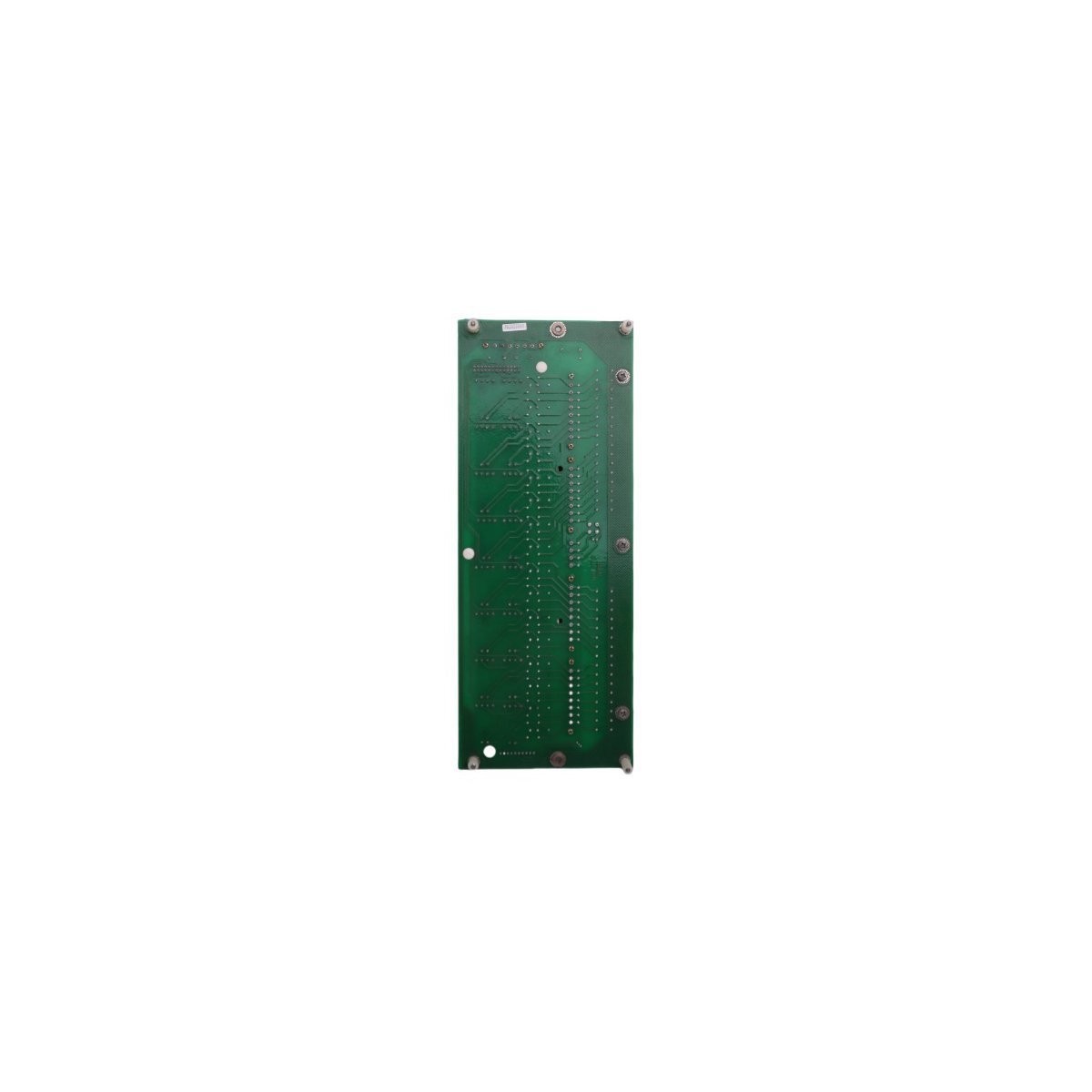
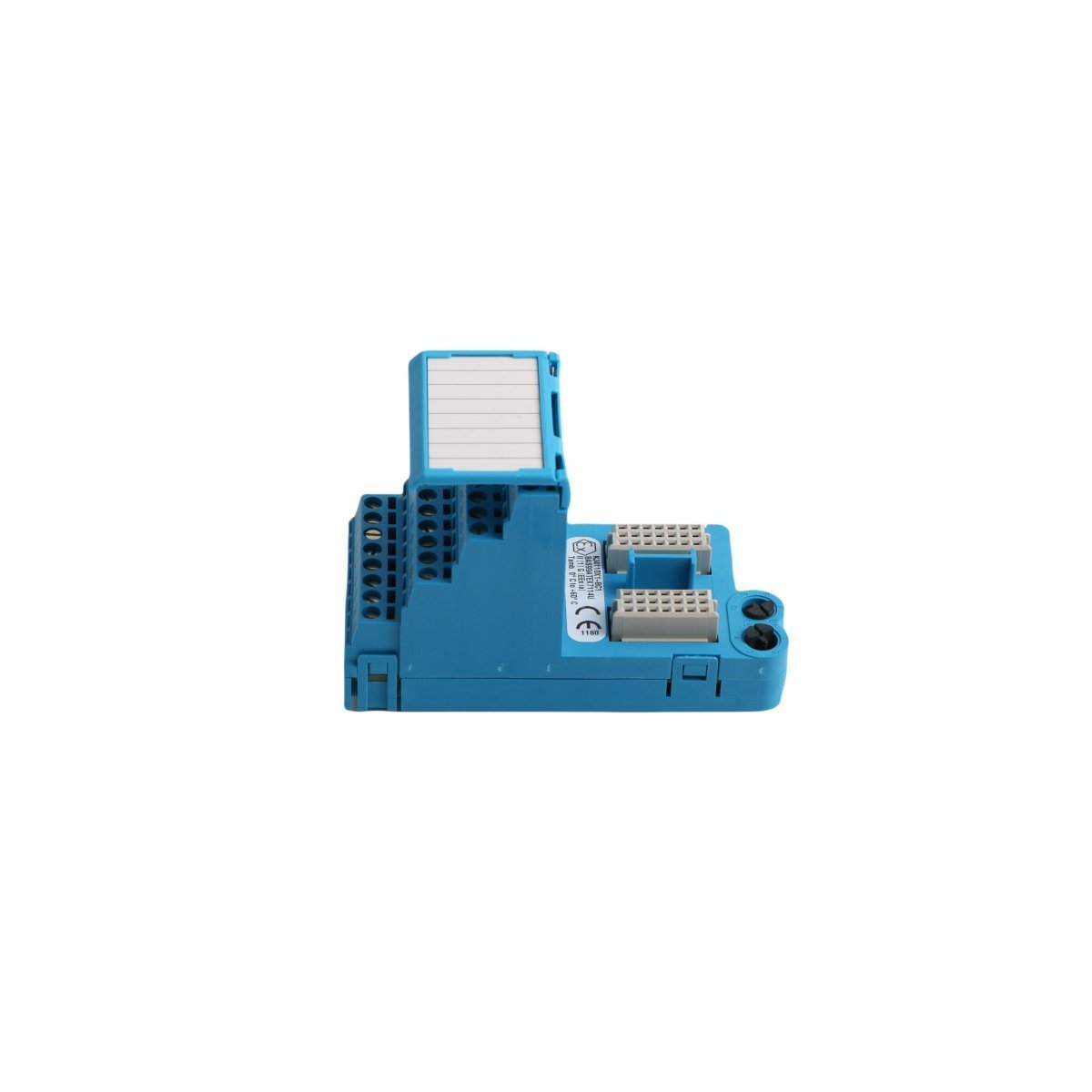
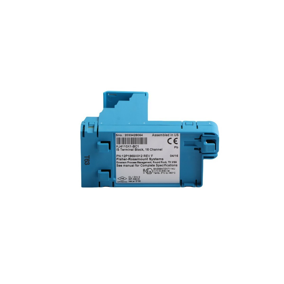
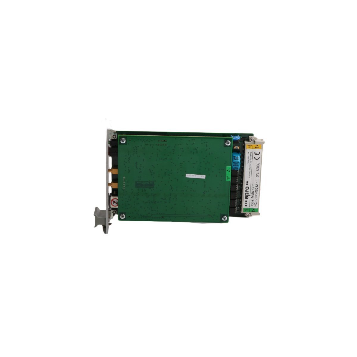
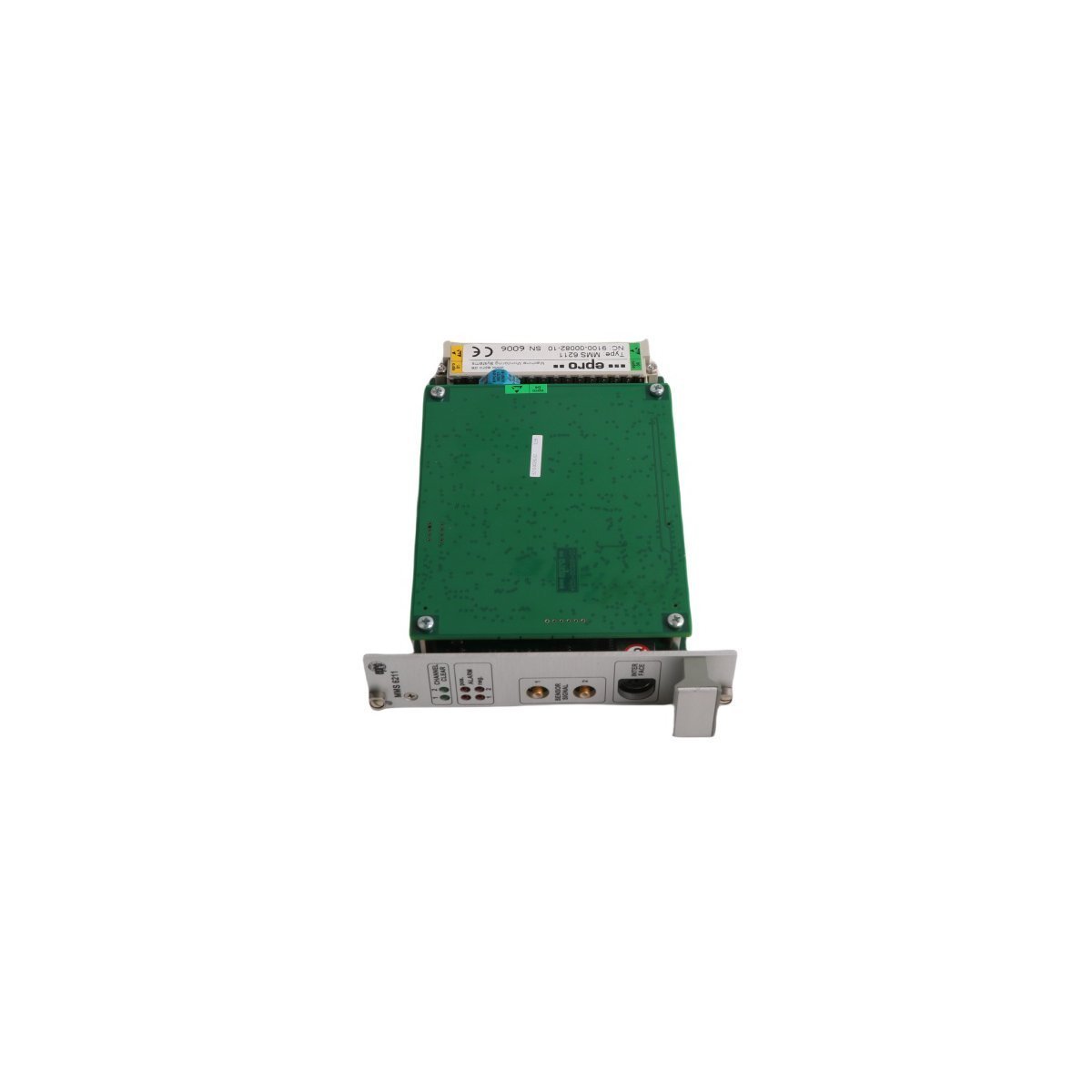
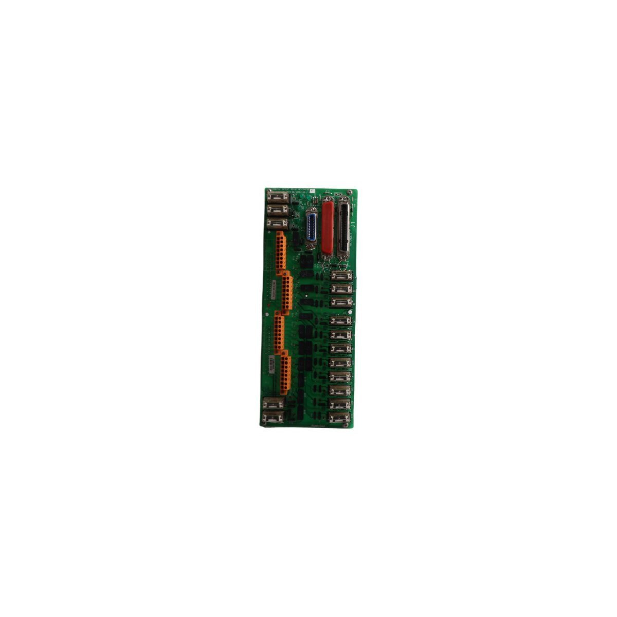
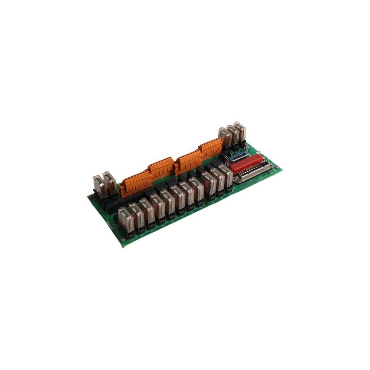
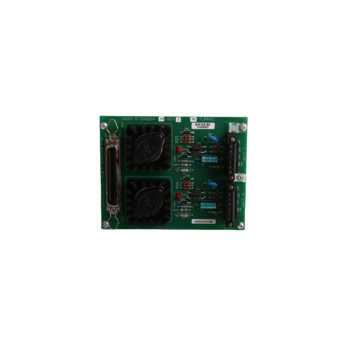
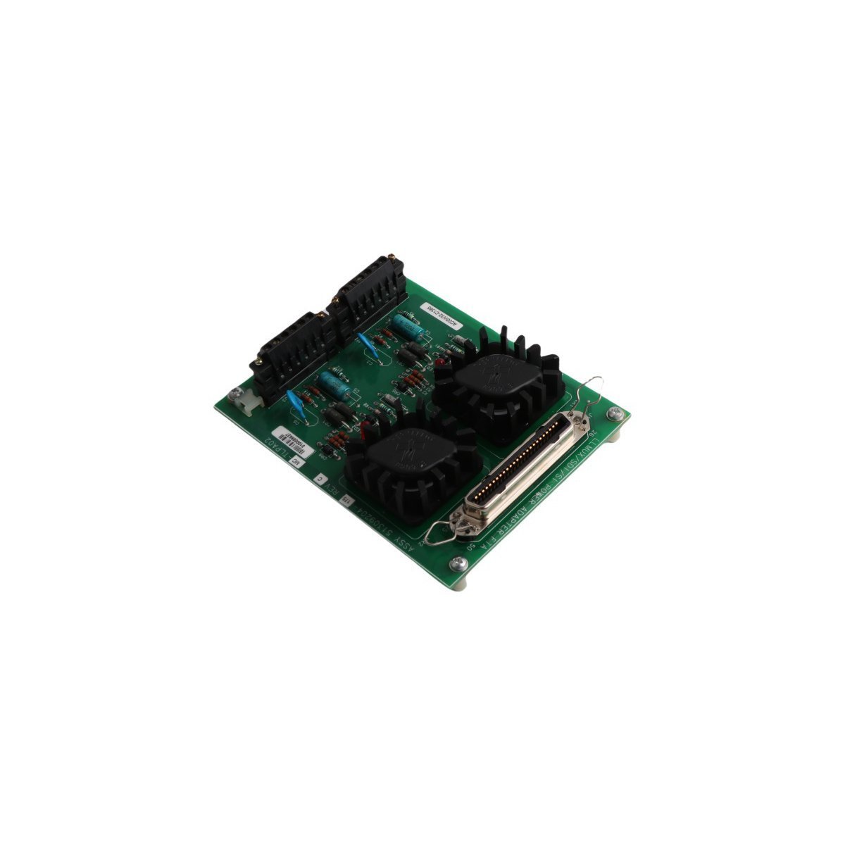
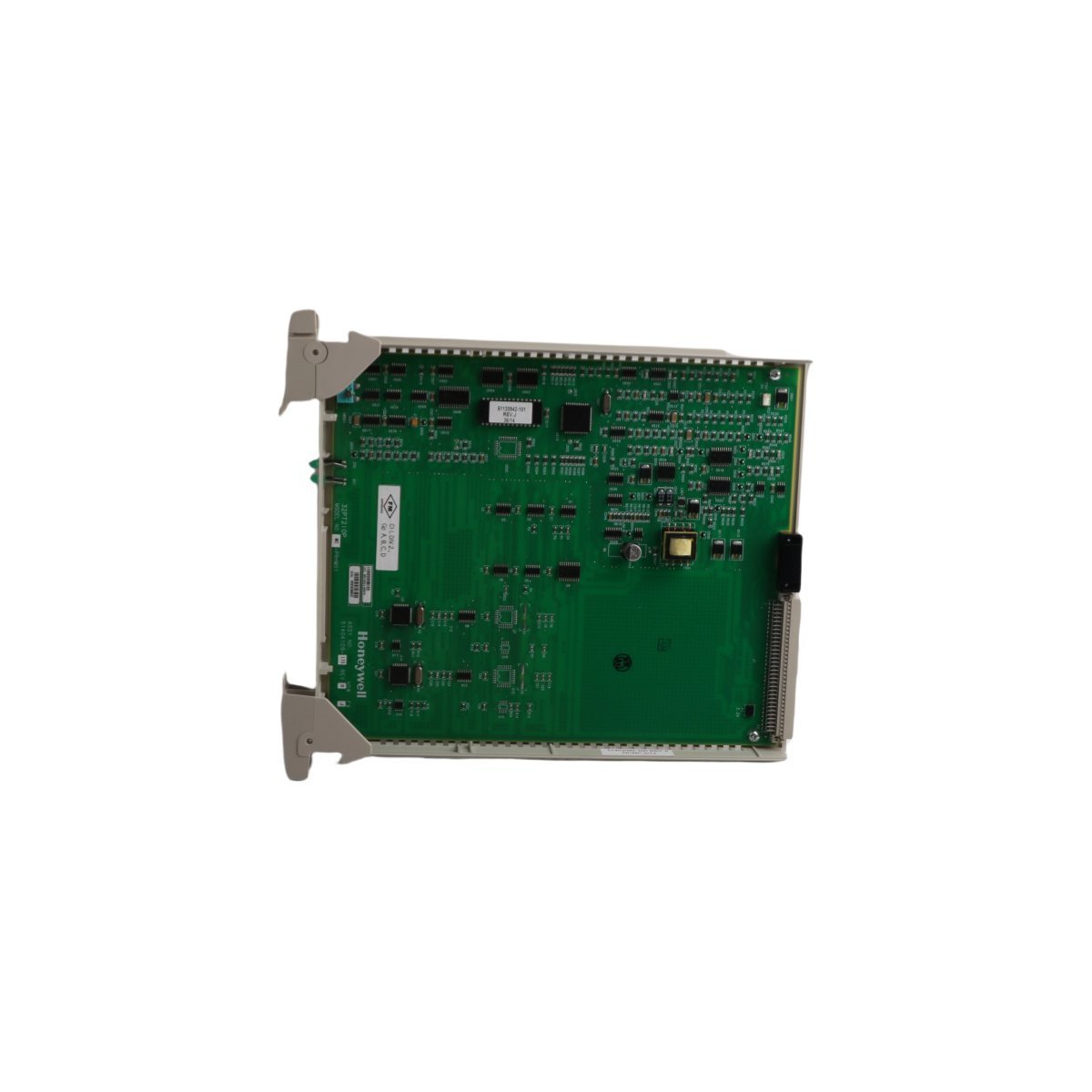
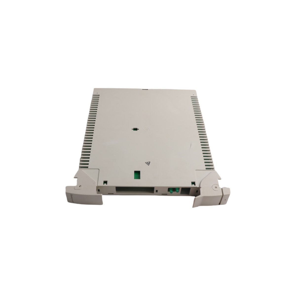
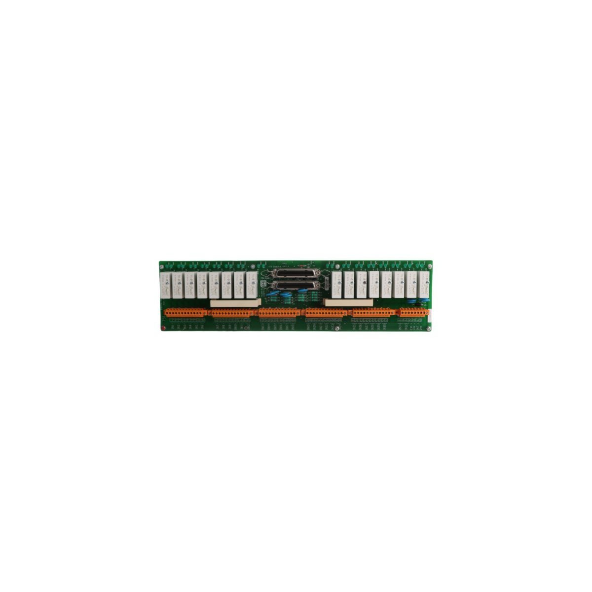
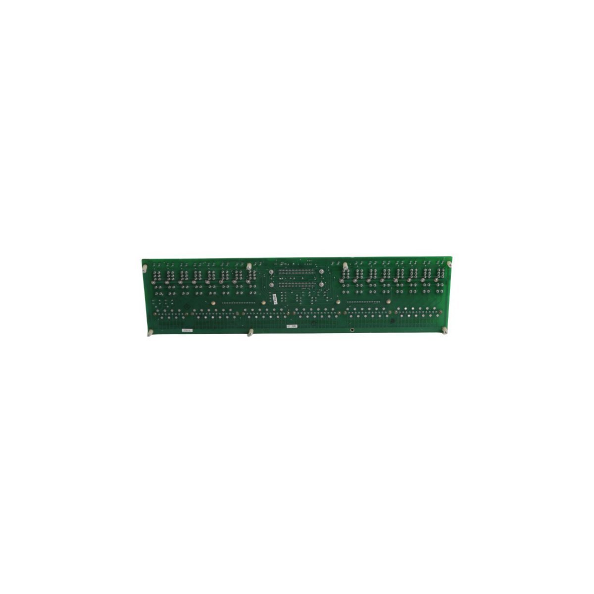
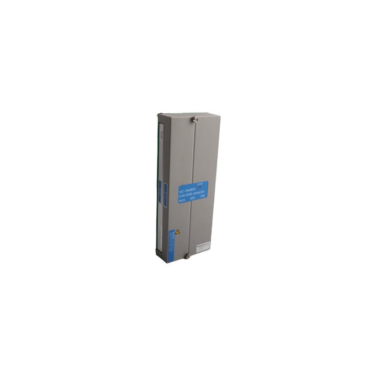
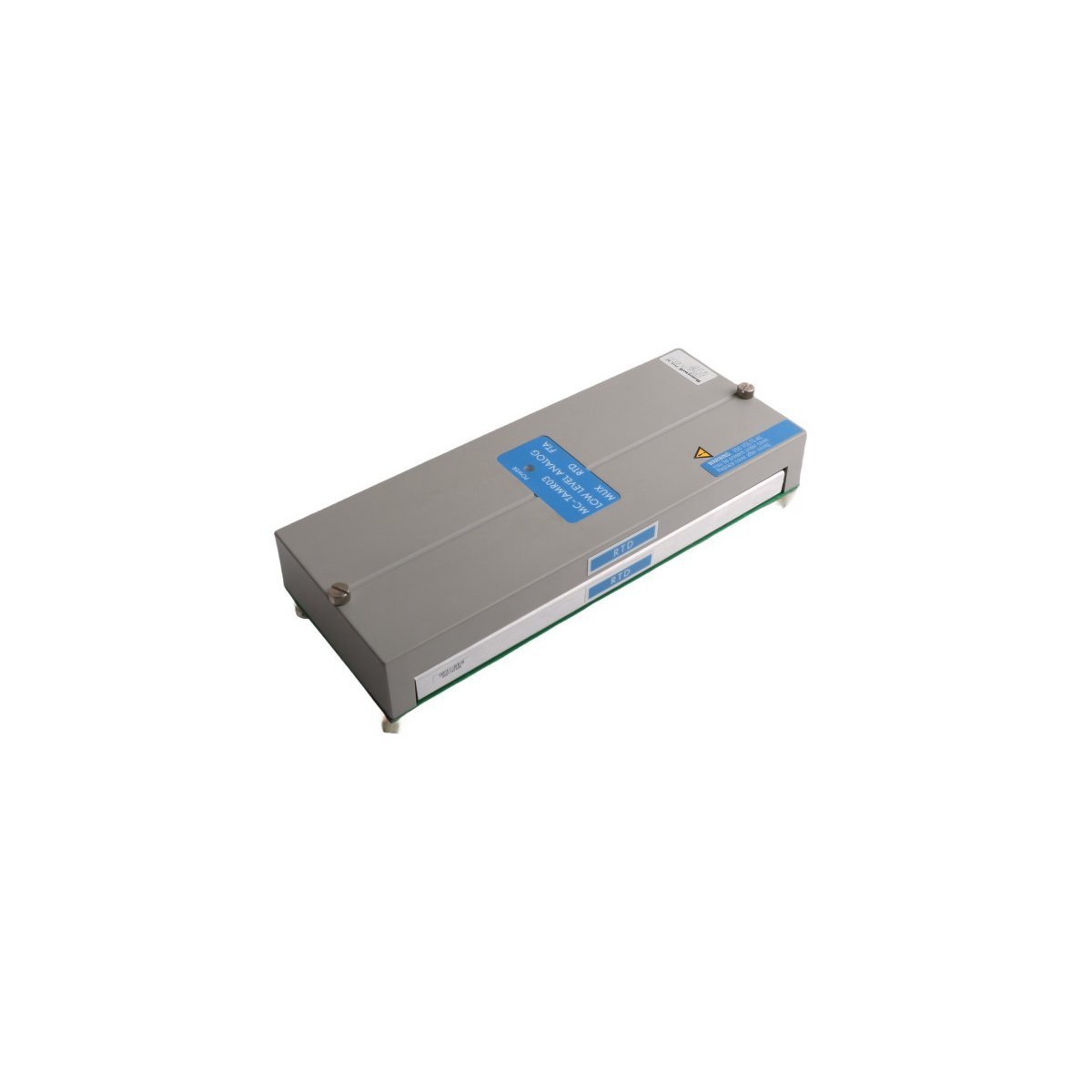
HONEYWELL MC-TAMT03 51309223-175 Multiplexer Thermocouple
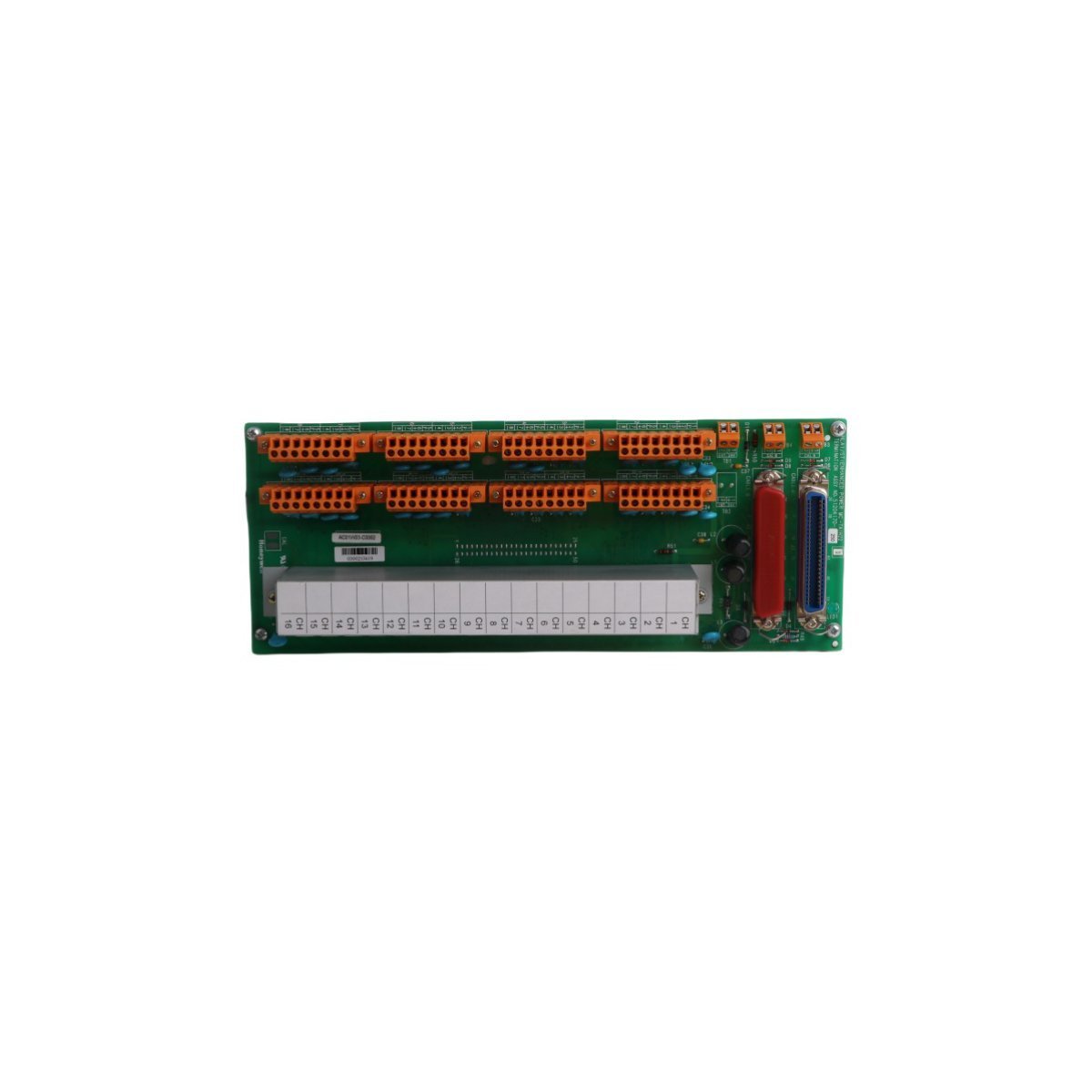
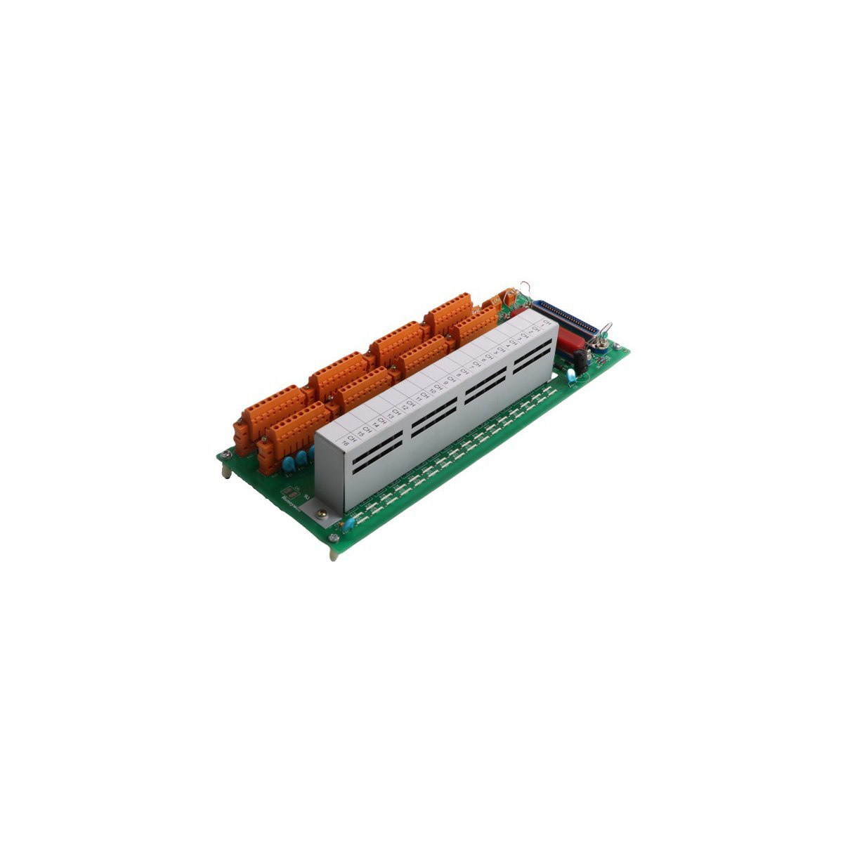
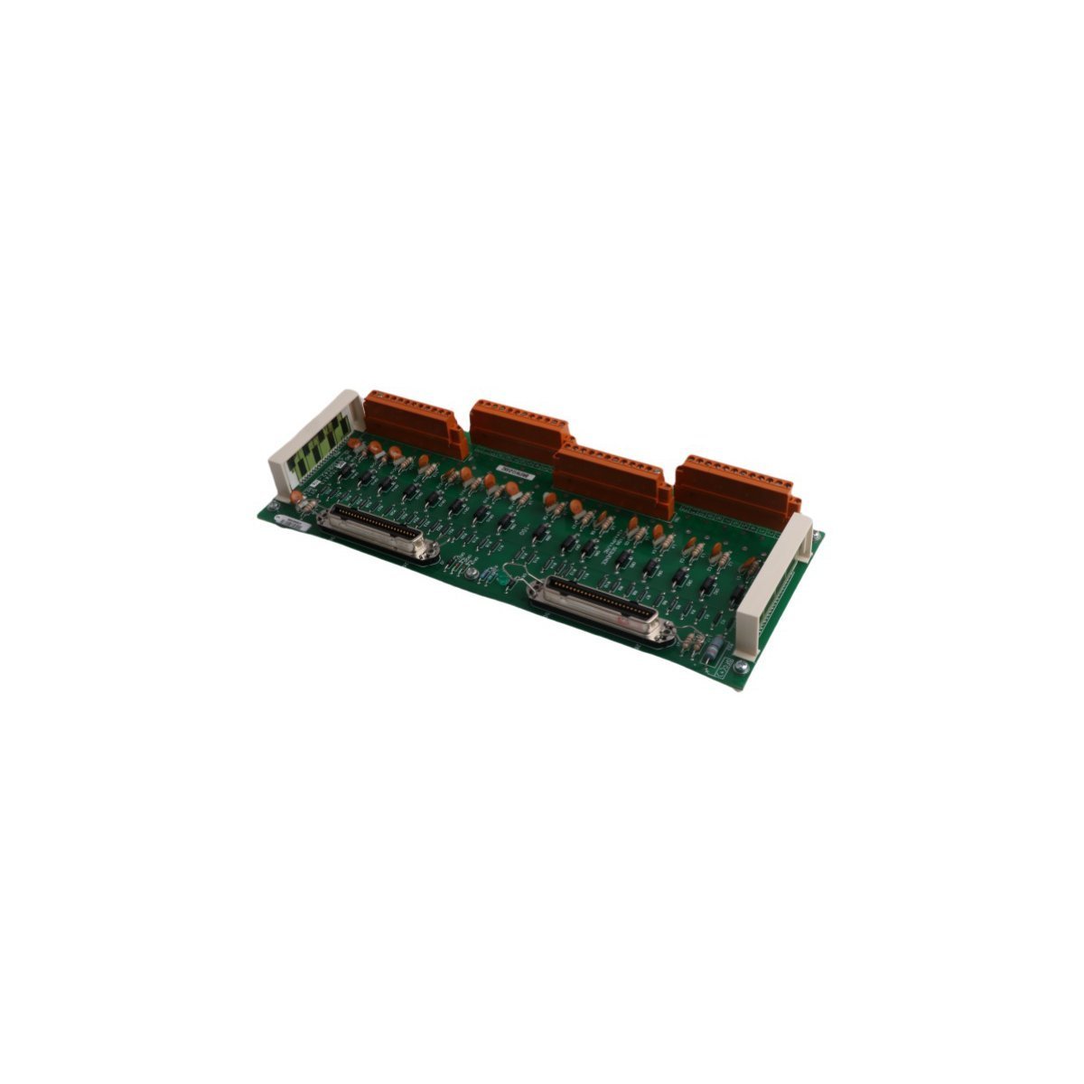
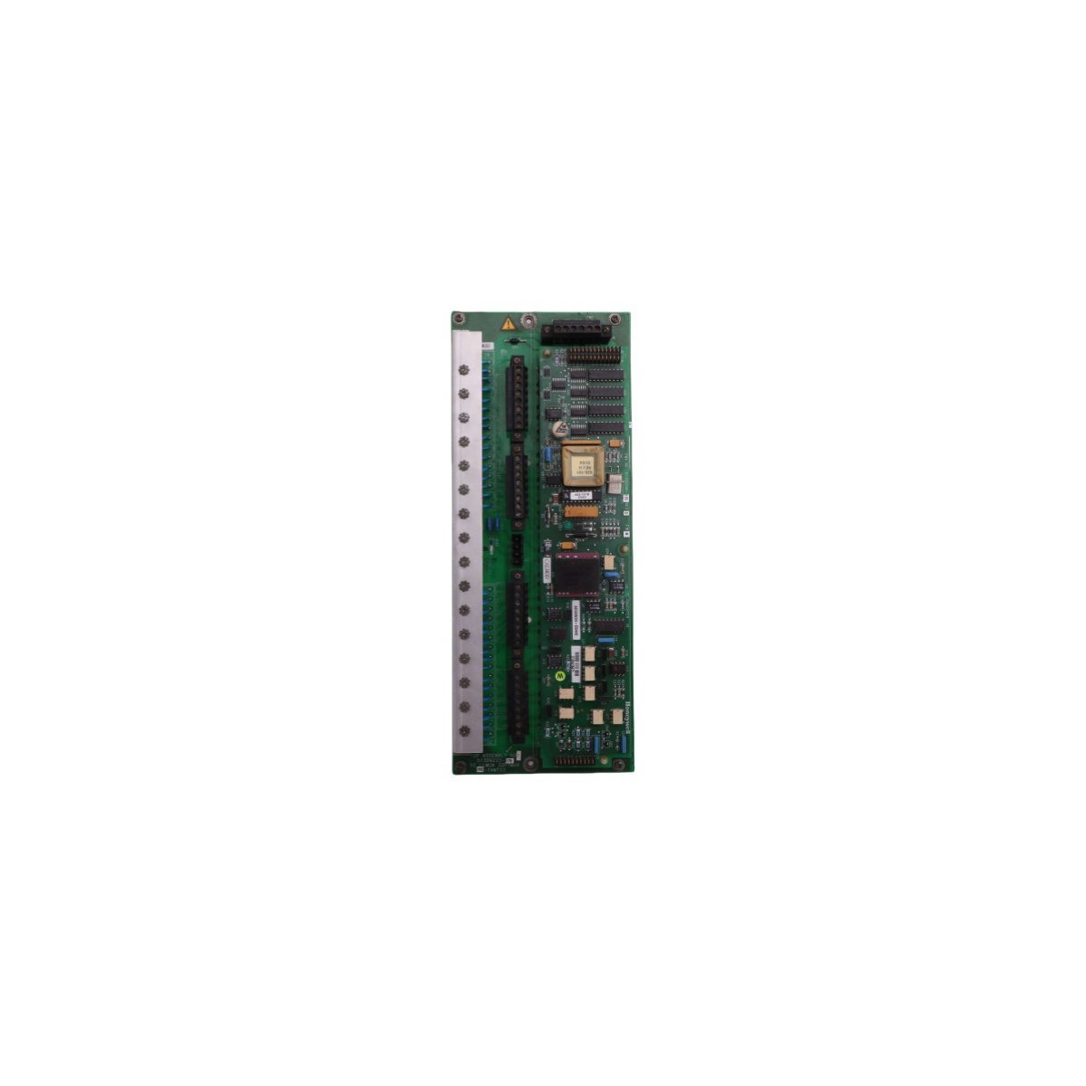
The HONEYWELL MC-TAMT03 51309223-175, also cataloged as the MC-TAMT03 51309223-175 Multiplexer Thermocouple, operates as a dedicated hardware component for multi-channel thermocouple signal acquisition within DCS platforms.
Hardware Specifications
| Parameter | Specification |
|---|---|
| Model | MC-TAMT03 51309223-175 |
| Brand | HONEYWELL |
| Origin | USA |
| Weight | 0.75 kg |
| Dimensions | 30.8 cm x 12.1 cm x 5 cm |
| Operating Temp | -40 deg C to +85 deg C |
| Power Consumption | System Backplane Dependent |
| Module Type | Multiplexer Thermocouple |
Process Control and DCS Connectivity
The MC-TAMT03 51309223-175 interfaces with thermocouple sensors to provide high-density input signal processing. It utilizes channel-to-channel isolation to prevent ground loops and common-mode noise during multi-point temperature measurement. Cold junction compensation (CJC) is performed internally to maintain measurement accuracy across the input terminal block. The module supports integration into DCS loops, where precise signal conditioning is required for control and monitoring routines.Frequently Asked Questions
Q: Does this module support field configuration of input types?A: Input configuration is managed through the DCS engineering workstation software; jumper settings or software-defined parameters must be aligned with the specific thermocouple type (e.g., Type J, K, T) connected to the terminal assembly.Q: Is hot-swapping permitted during system operation?A: Module removal must be performed in accordance with Honeywell MU-T series maintenance procedures, ensuring that the associated control loops are in manual or bypass mode to prevent process instability.Field Installation Guidelines
- First, the control cabinet power must be verified as disconnected, and the local grounding integrity of the rack must be confirmed.
- Subsequently, the module must be aligned with the designated MU-T series slot guide rails so that pin damage is avoided.
- Once the module is fully seated, it must be secured by the integrated mechanical retention tabs.
- Furthermore, thermocouple wiring must be routed in shielded twisted-pair cabling away from high-voltage AC lines so that electromagnetic interference is mitigated; additionally, dedicated wire ducts must be utilized for all field signal conductors.
- Finally, signal continuity at the termination points must be checked after installation so that a valid physical link to the DCS backplane is confirmed.