Sale!
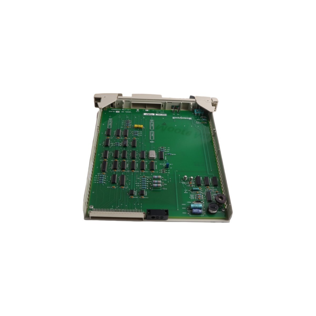
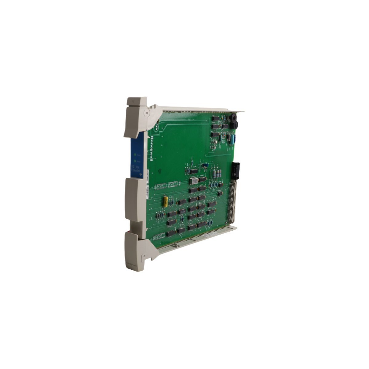
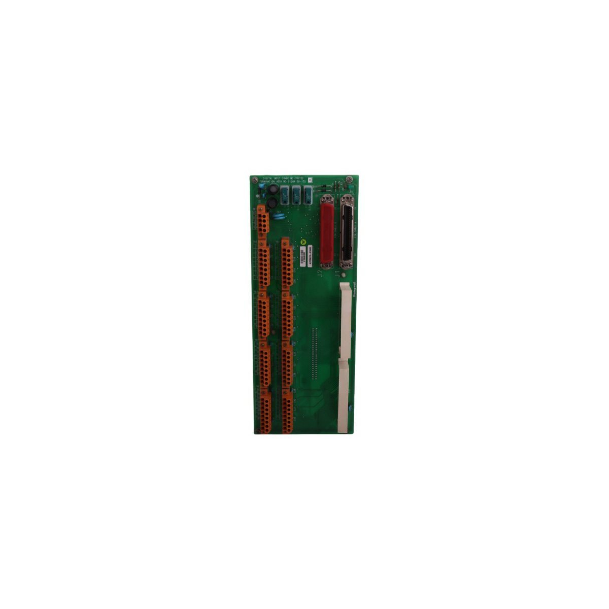
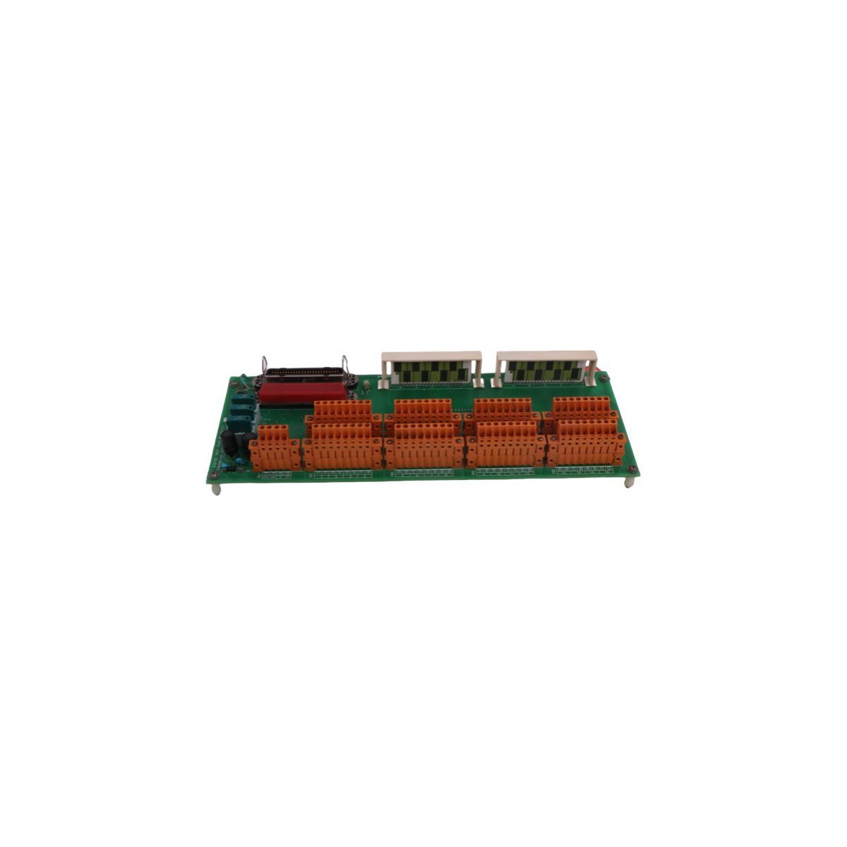
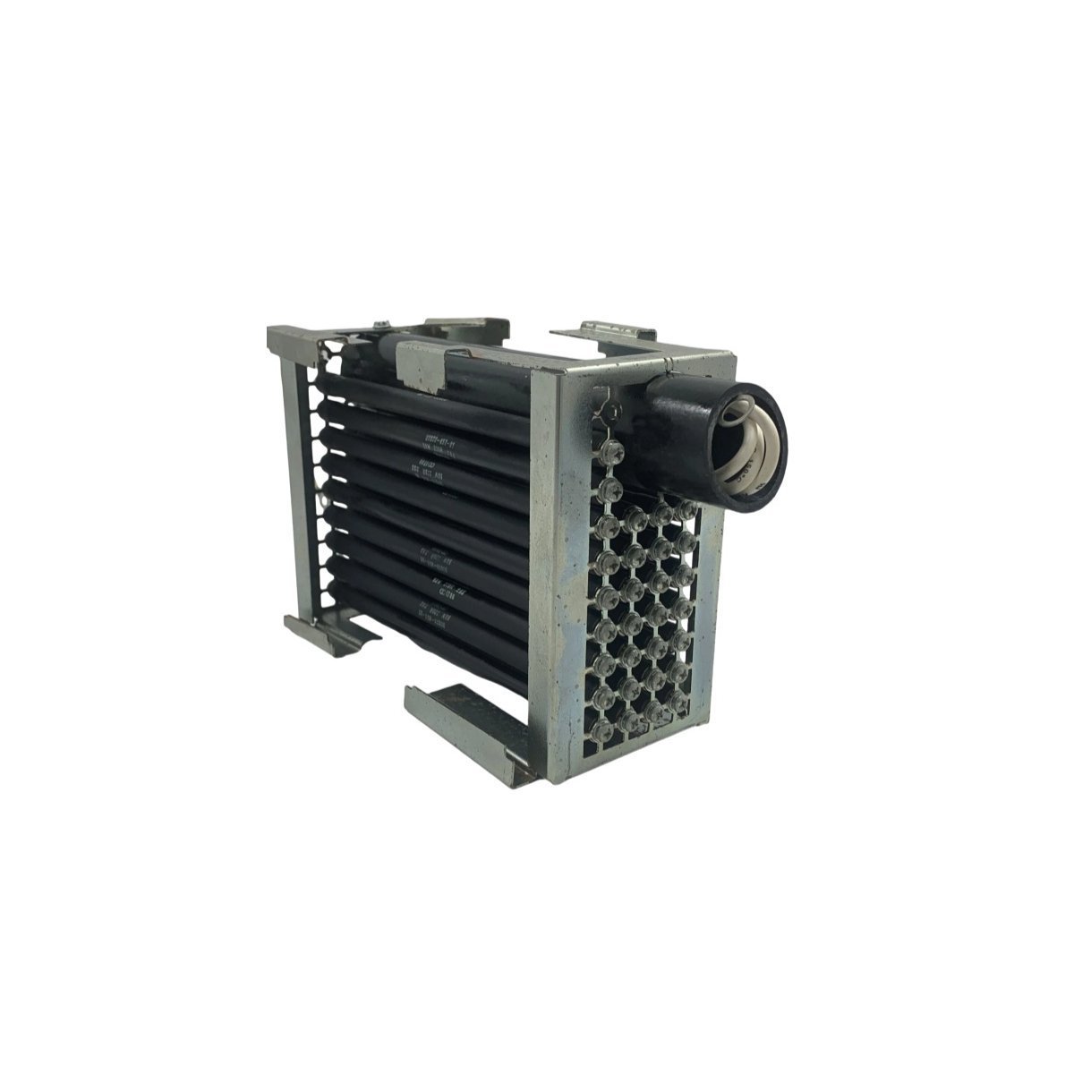
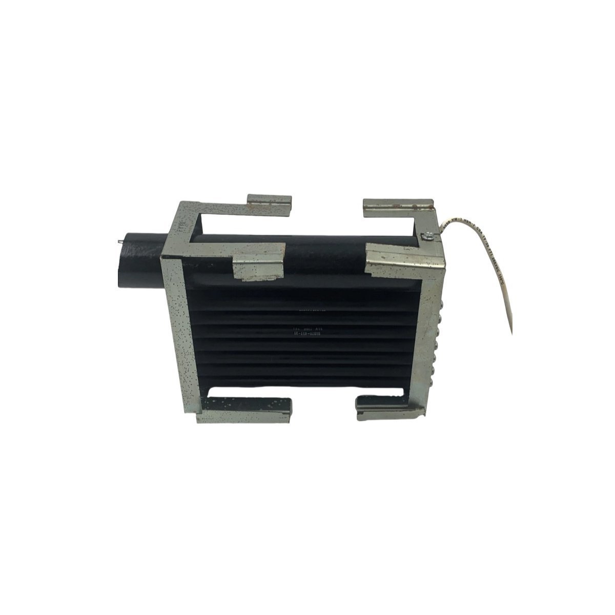
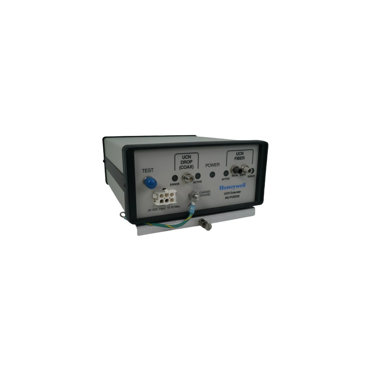
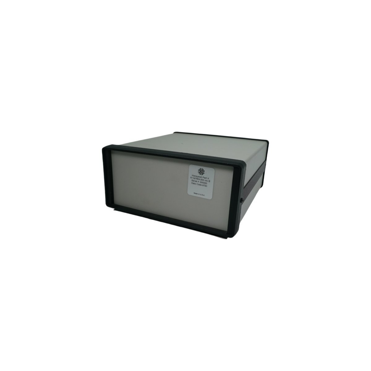
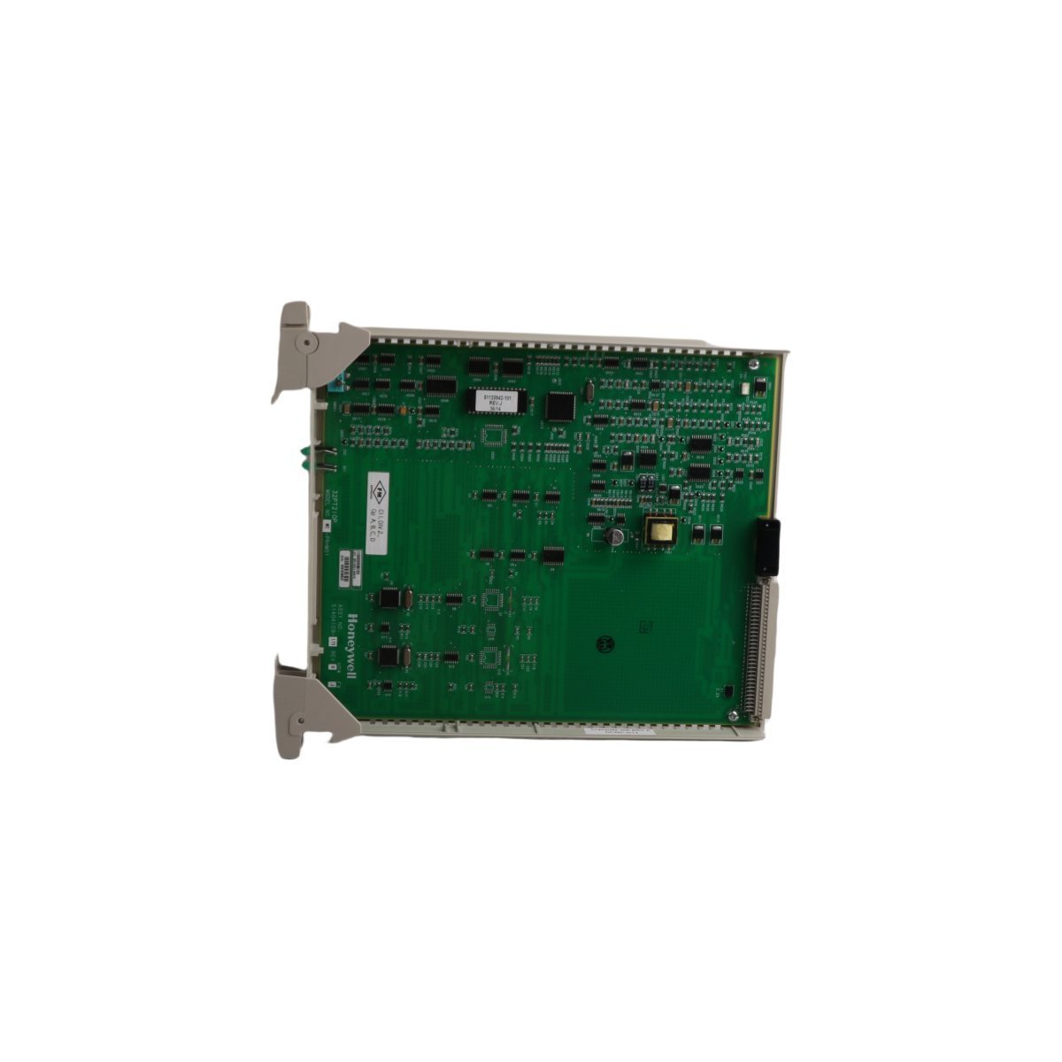
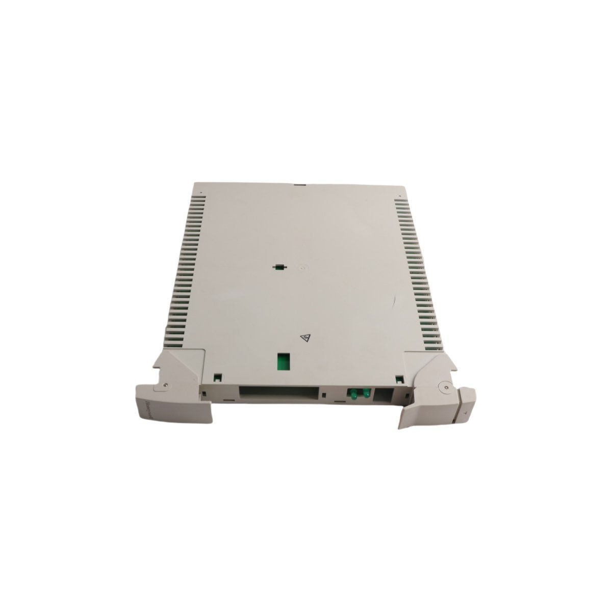
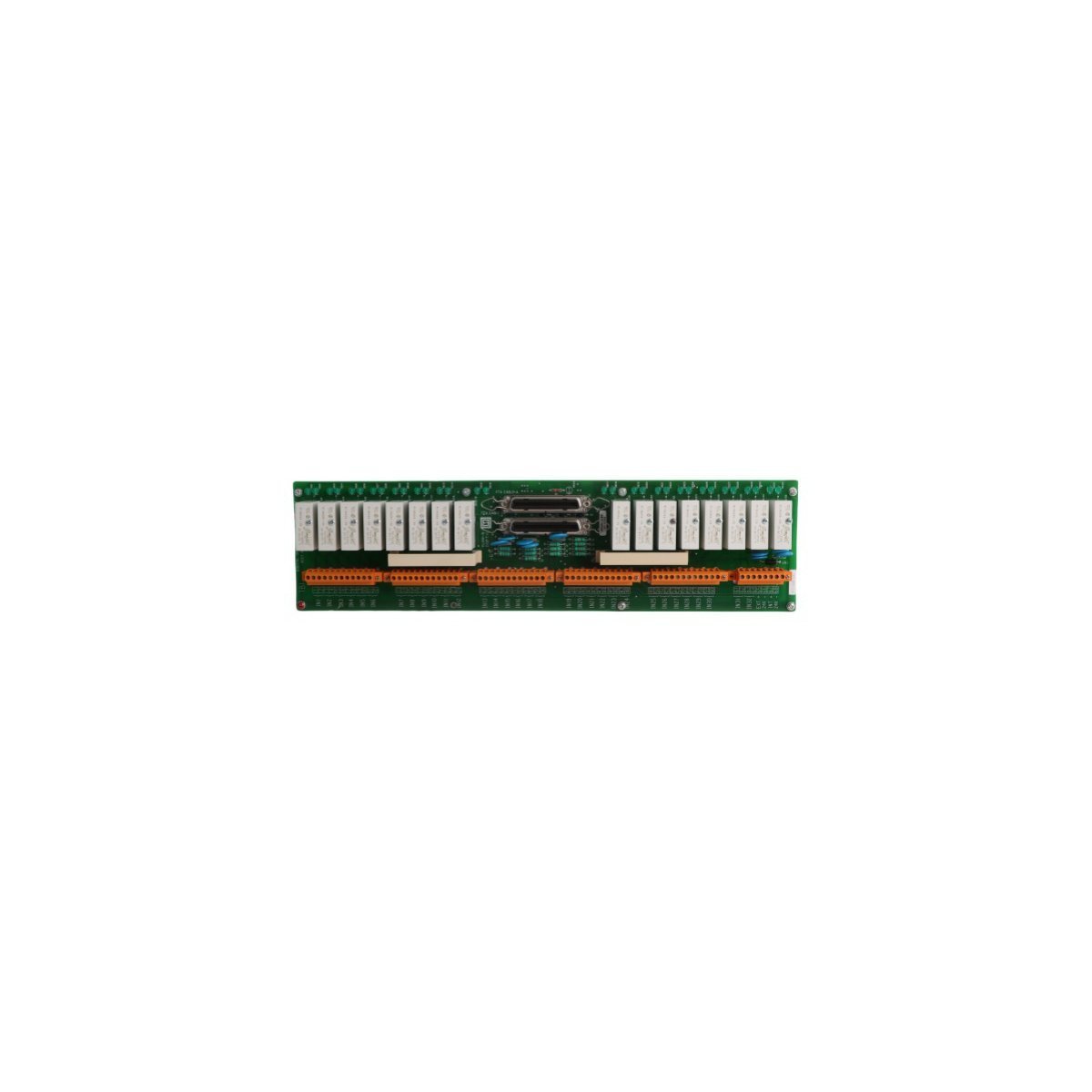
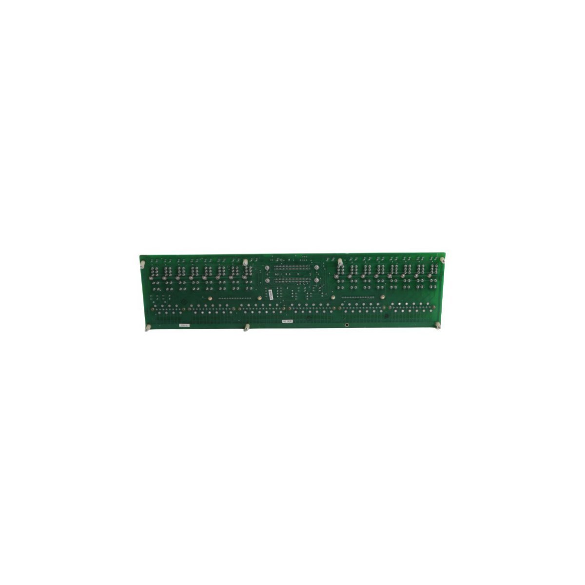
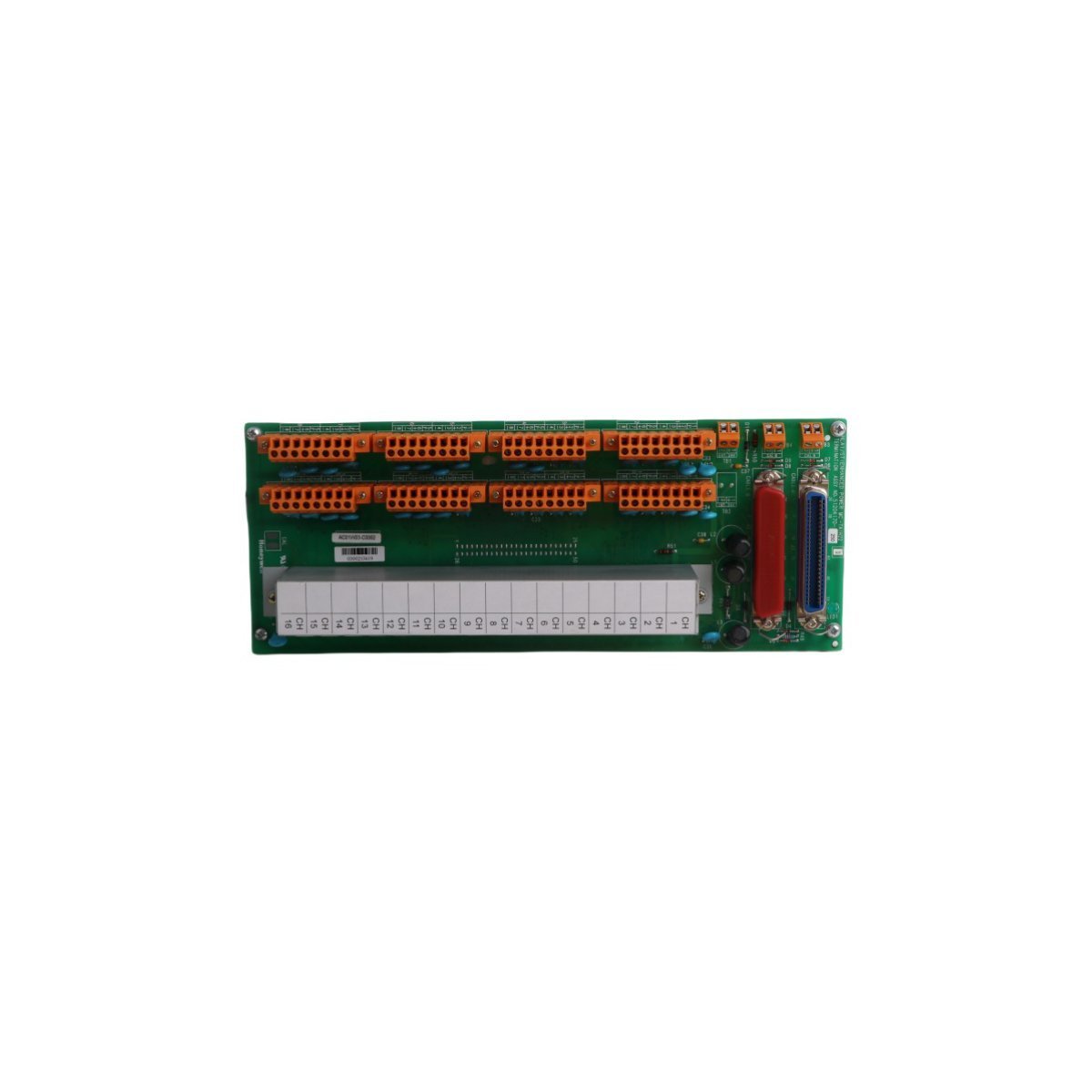
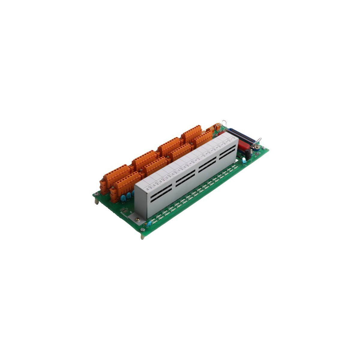
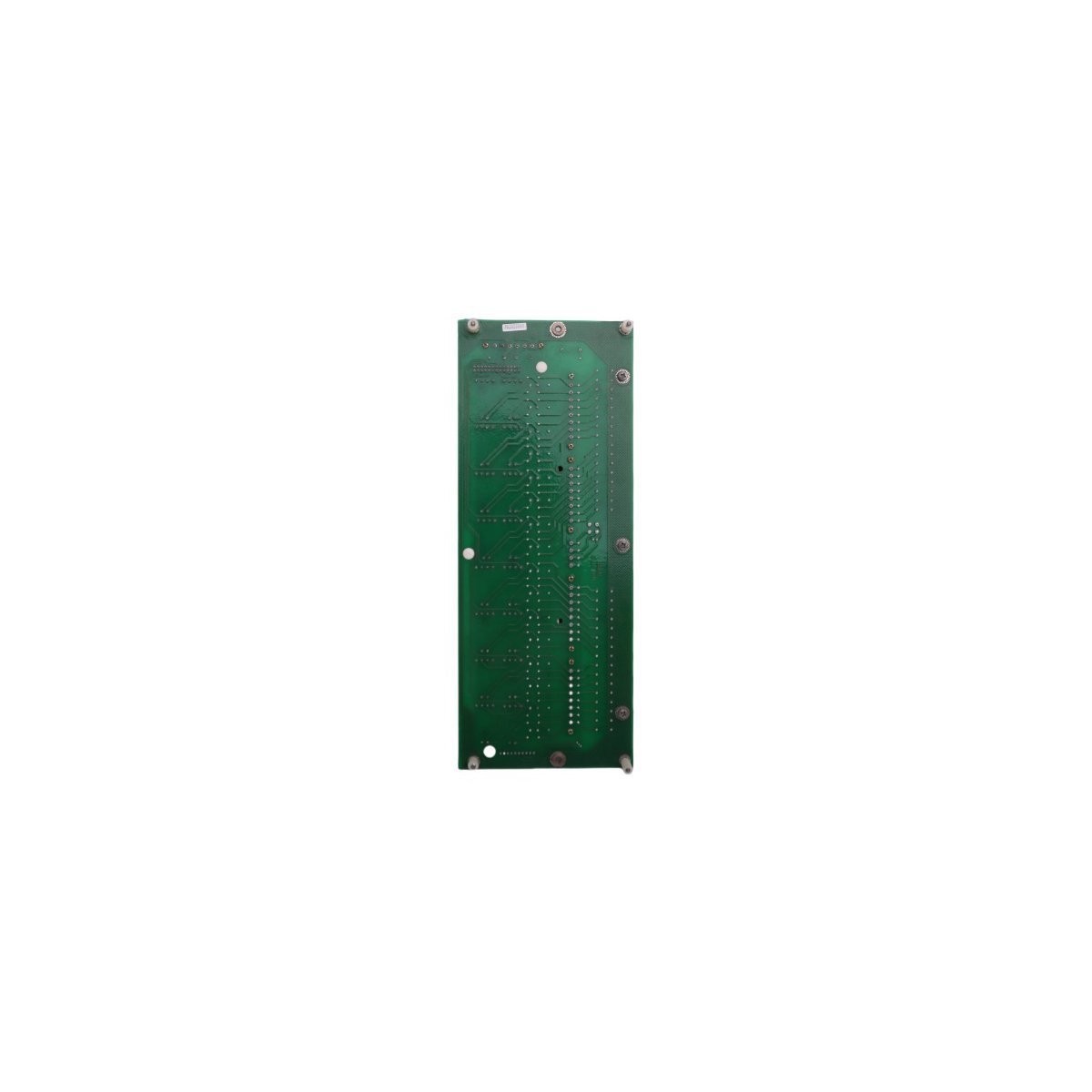
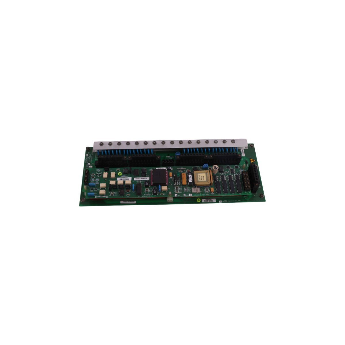
Honeywell MC-IOLX02 I/O Link Extender Card
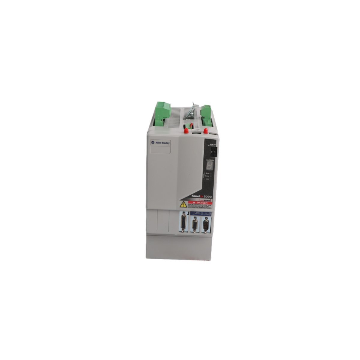
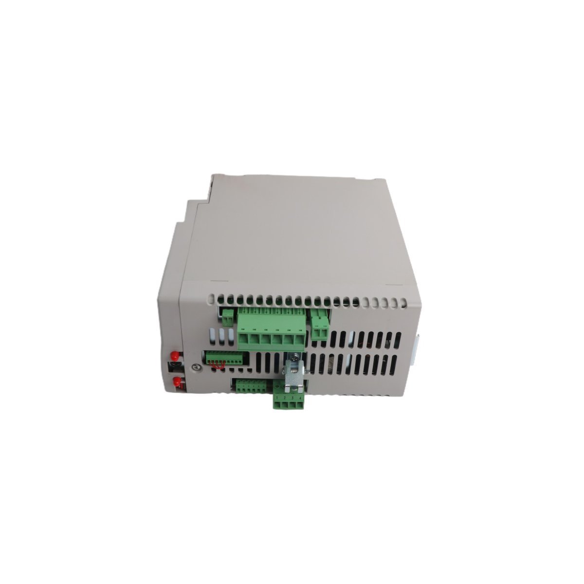
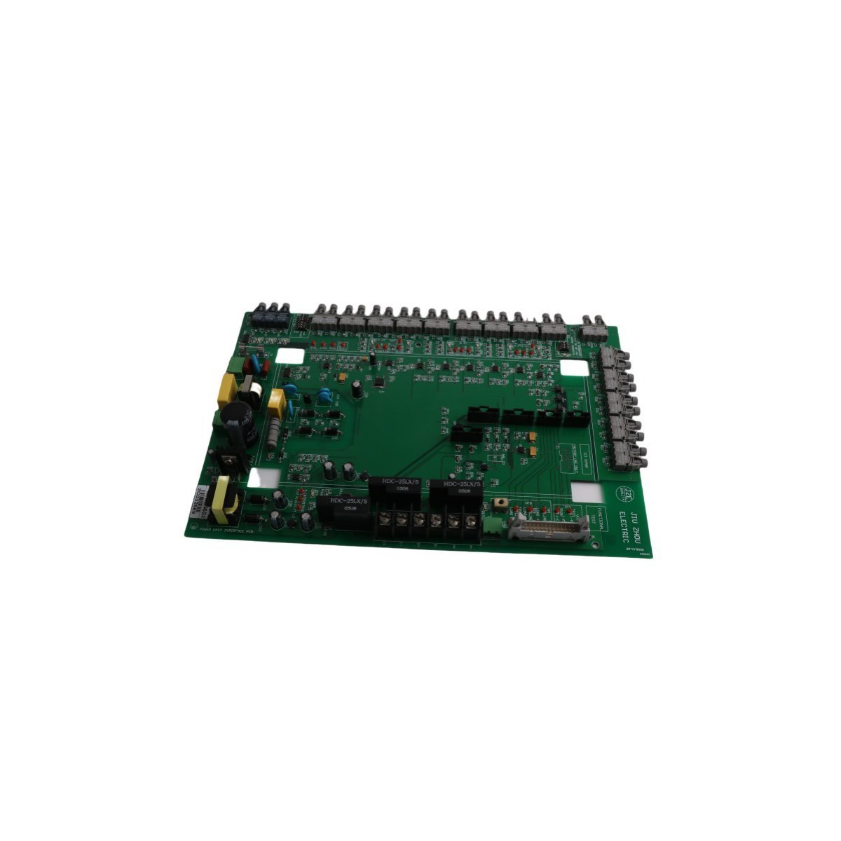
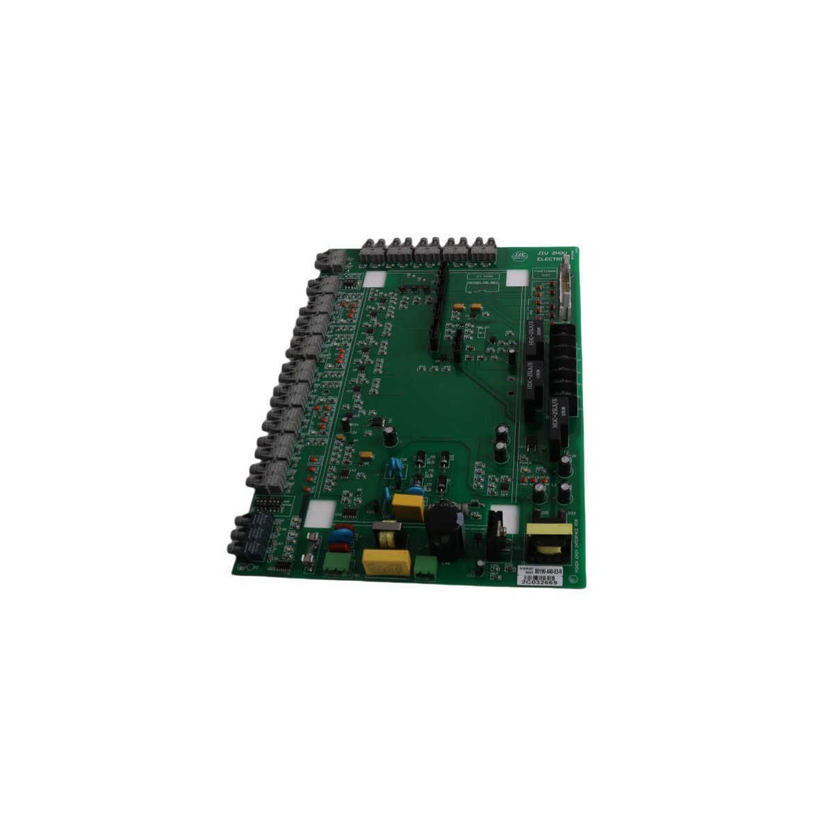
The Honeywell MC-IOLX02, also cataloged as the 51304419-150 I/O Link Extender Card, operates as a dedicated hardware component for signal expansion and physical layer coupling within distributed control system (DCS) architectures.
Hardware Specifications
| Parameter | Specification |
|---|---|
| Model | MC-IOLX02 |
| Brand | Honeywell |
| Origin | USA |
| Weight | 0.58 kg |
| Dimensions | 3 x 31.8 x 27.8 cm |
| Operating Temp | Industrial standard |
| Power Consumption | System-bus dependent |
| Product Range | MU-T Series |
| Communication Service | Ethernet router |
Process Control and DCS Connectivity
The Honeywell MC-IOLX02 facilitates signal integrity across DCS loops by managing communication pathways between field-level devices and higher-level processing nodes. The module integrates 4-20 mA HART loop protocol standards, allowing for seamless integration with legacy instrumentation and modern smart field devices. Channel-to-channel isolation is implemented to mitigate electromagnetic interference, ensuring that analog signals remain stable even under high-density wiring conditions. The architecture supports standard HART digital communication overlays, providing diagnostics and configuration data without disrupting the primary process control loop.Frequently Asked Questions
Q: Does the MC-IOLX02 support hot-swap functionality within the MU-T Series rack?A: Yes, the module is designed for insertion and extraction under power; however, control logic must be verified to ensure the I/O state transition does not trigger an unexpected process response.Q: What is the primary function of the Ethernet router service integrated into this module?A: The onboard communication service manages data packet routing between the I/O link and the system backplane to ensure deterministic timing for process variables.Q: Are there specific shielding requirements for the input cabling connected to this card?A: Yes, all signal cabling must utilize high-quality twisted-pair shielded cables with the shield grounded at the cabinet entry point to maintain signal-to-noise ratios.Field Installation Guidelines
Initially, ensure the control cabinet power is isolated before inserting the module into the designated slot of the MU-T Series backplane.
Subsequently, verify that the mechanical guides are correctly aligned before applying the necessary force to seat the card connector.
Following this, secure the module using the provided captive screws to maintain vibration resistance and establish a low-impedance electrical contact with the backplane ground rail.
Simultaneously, route all field wiring separately from high-voltage AC power lines to prevent induced noise on the I/O channels.
Finally, perform a point-to-point wiring continuity check to confirm circuit integrity before initiating system-level loop configuration.