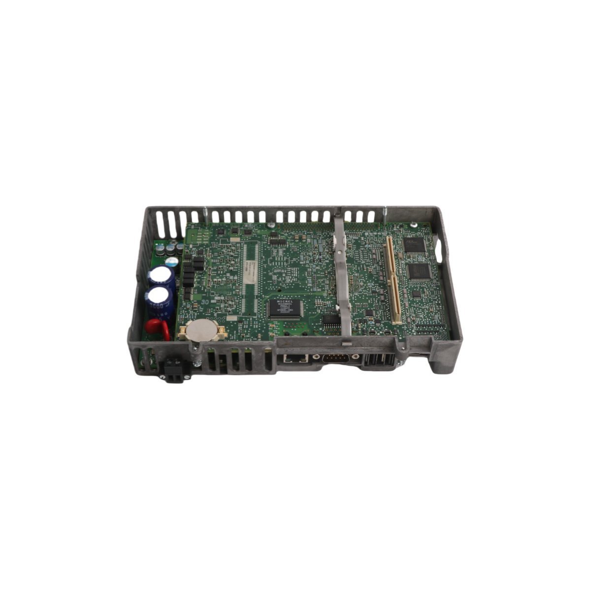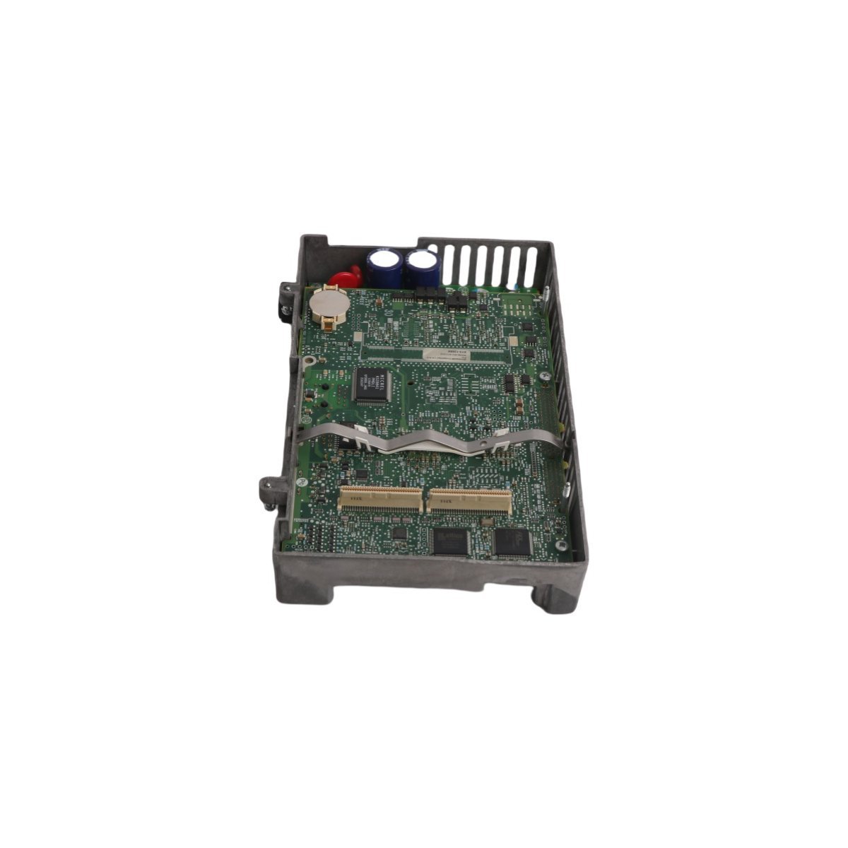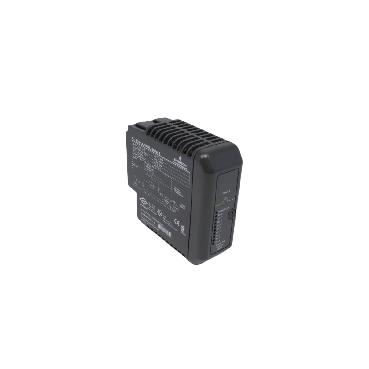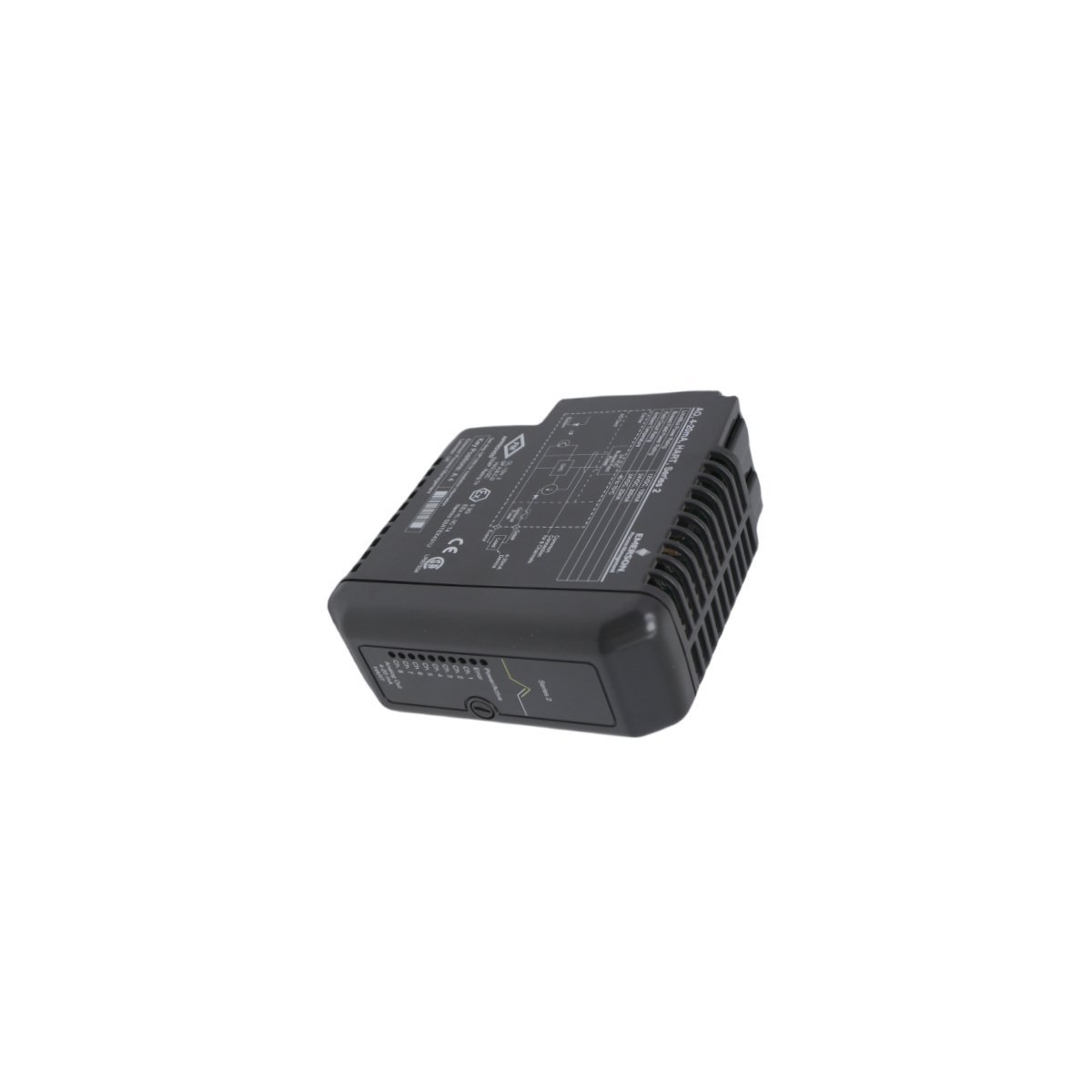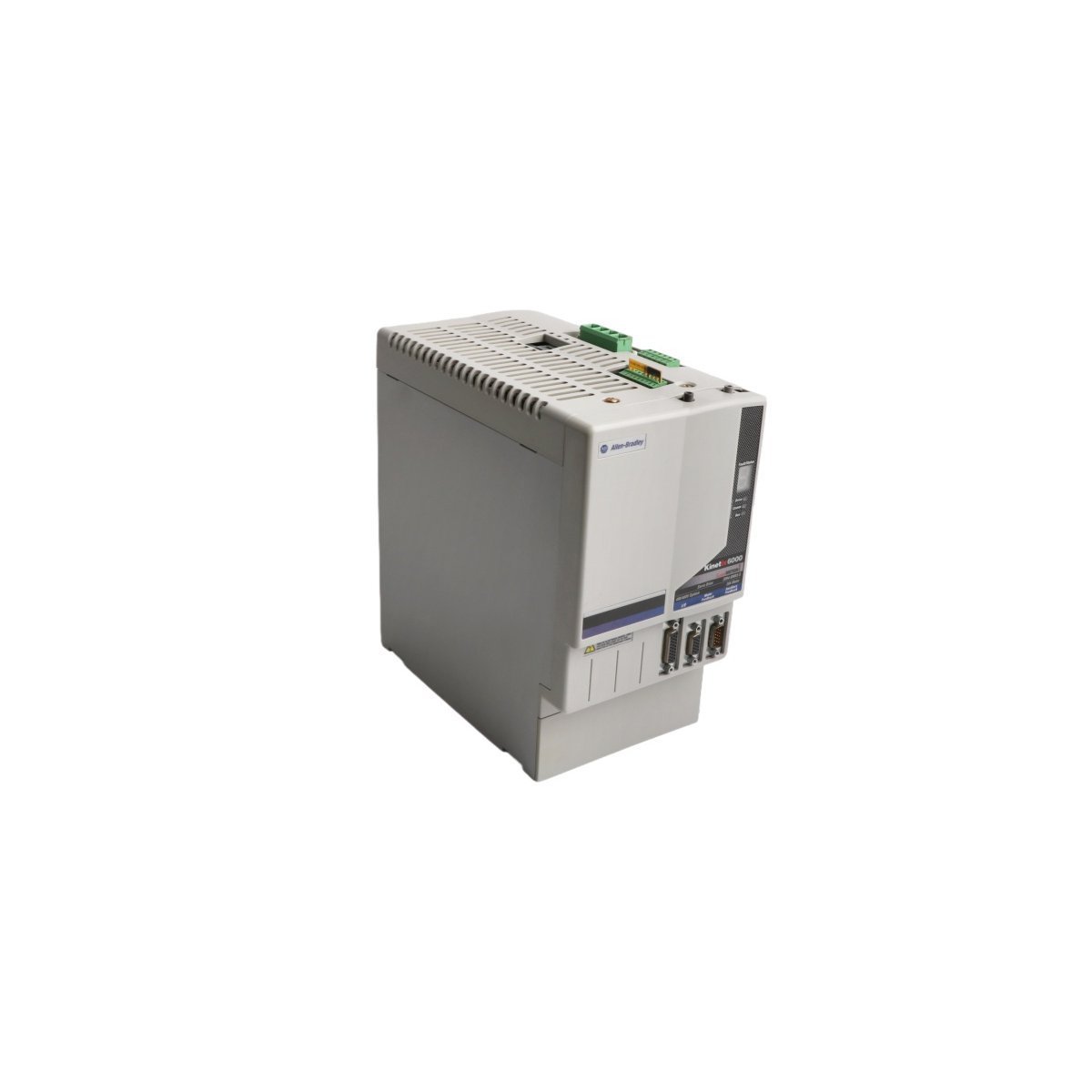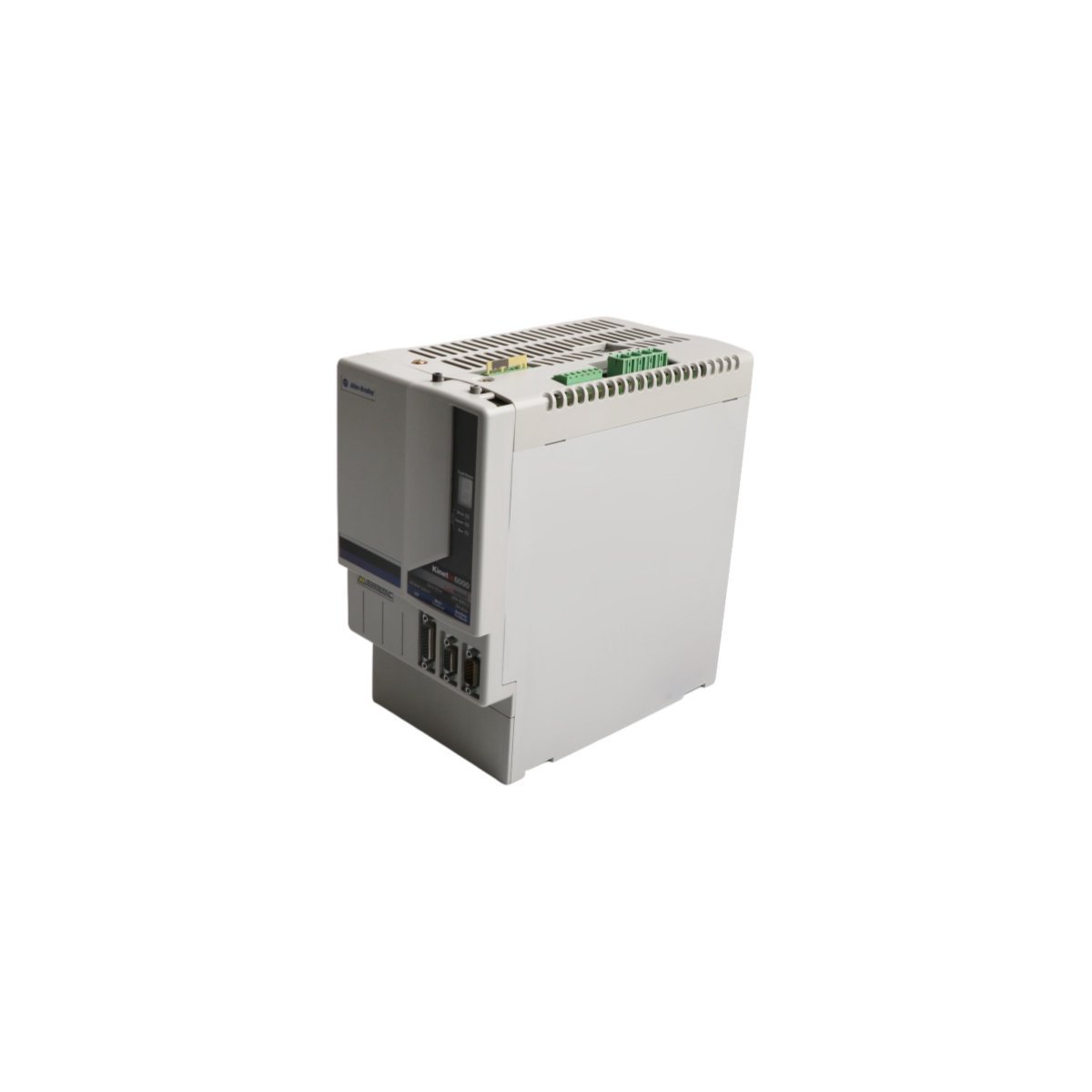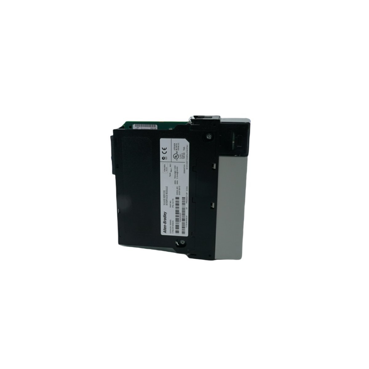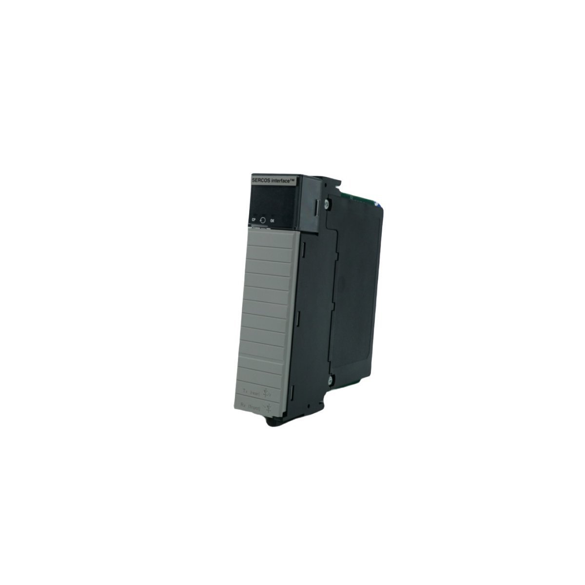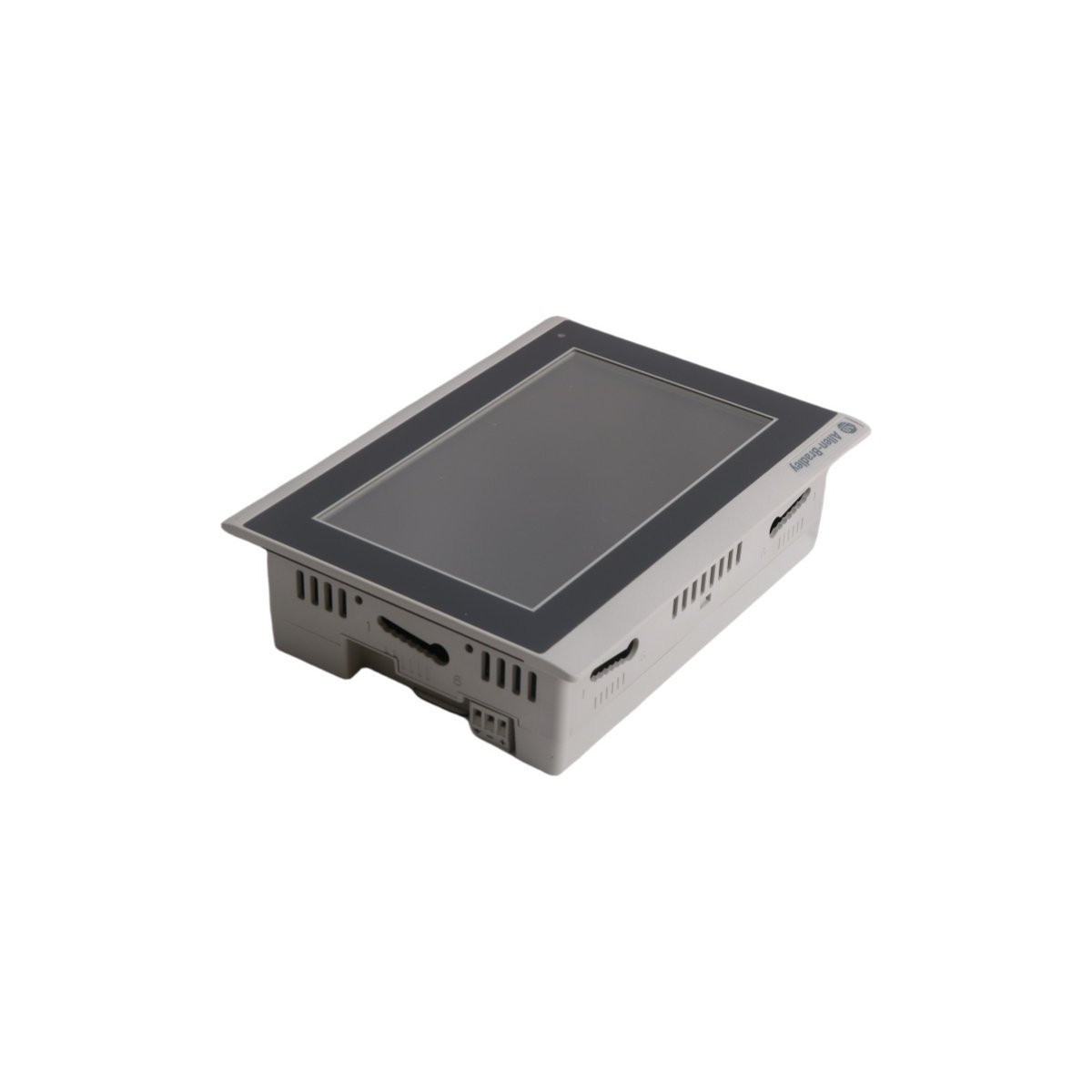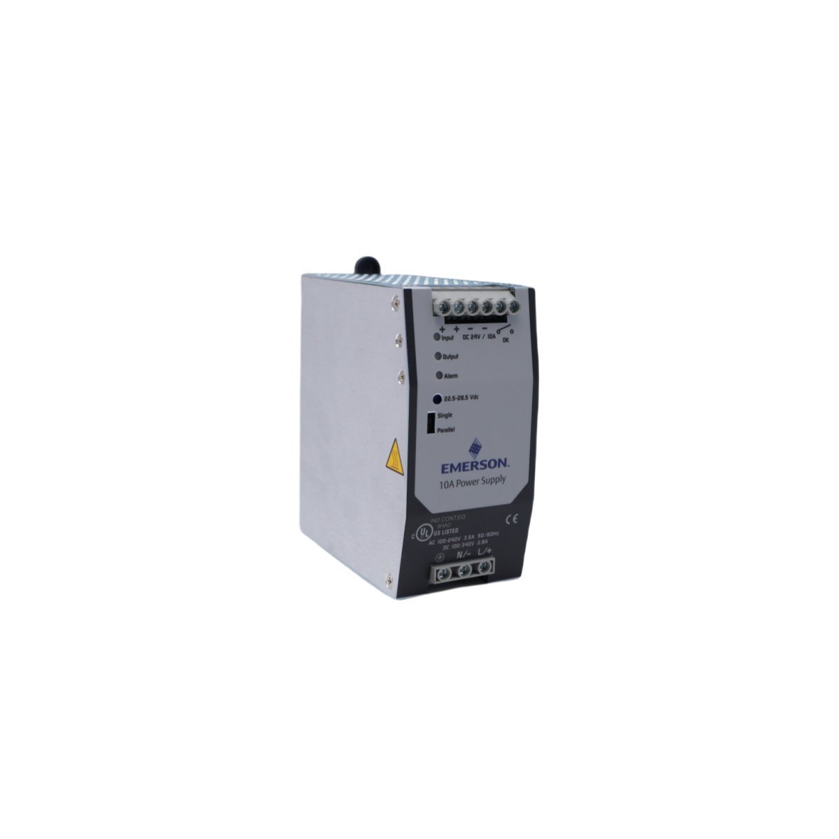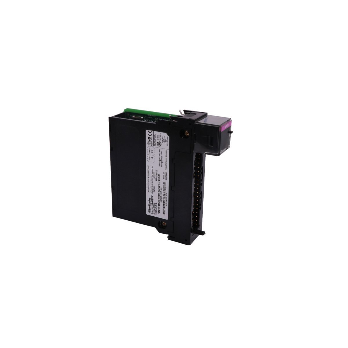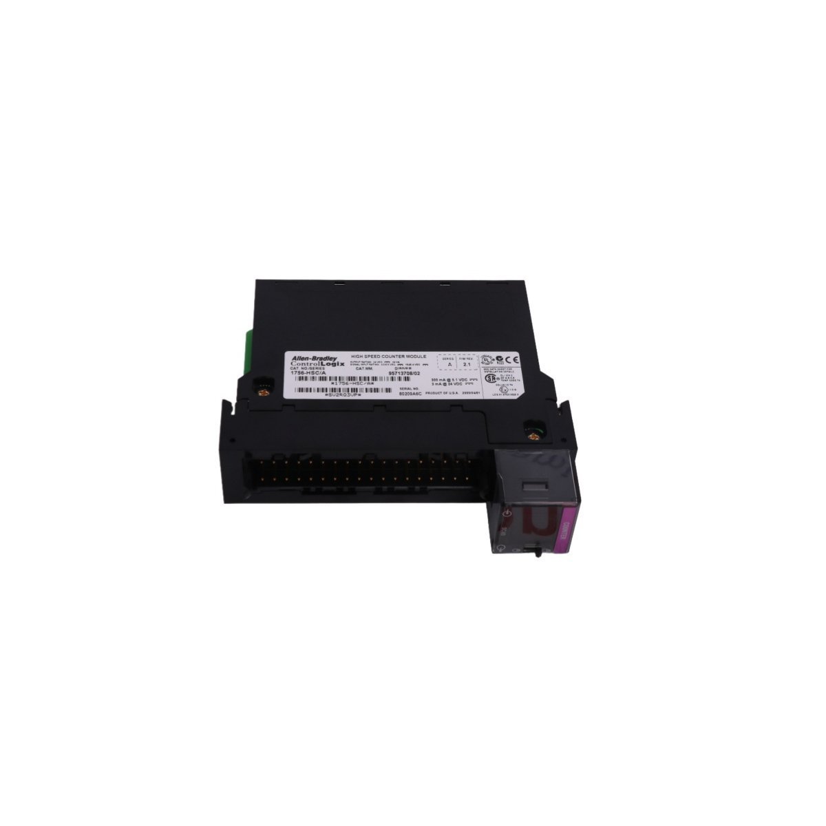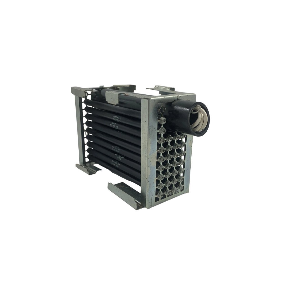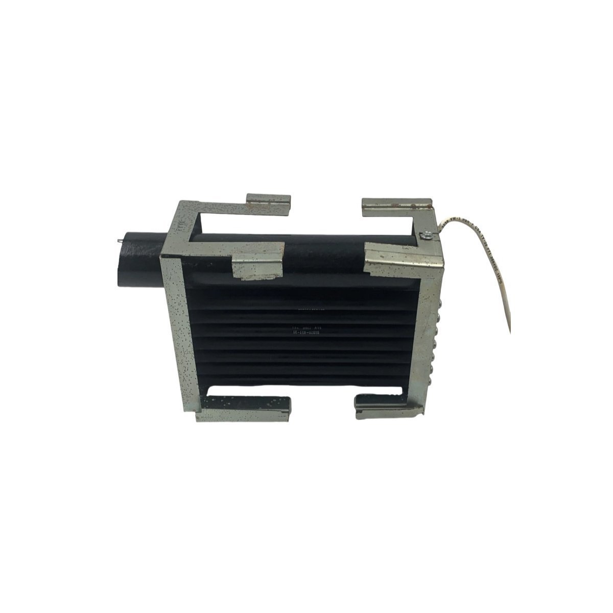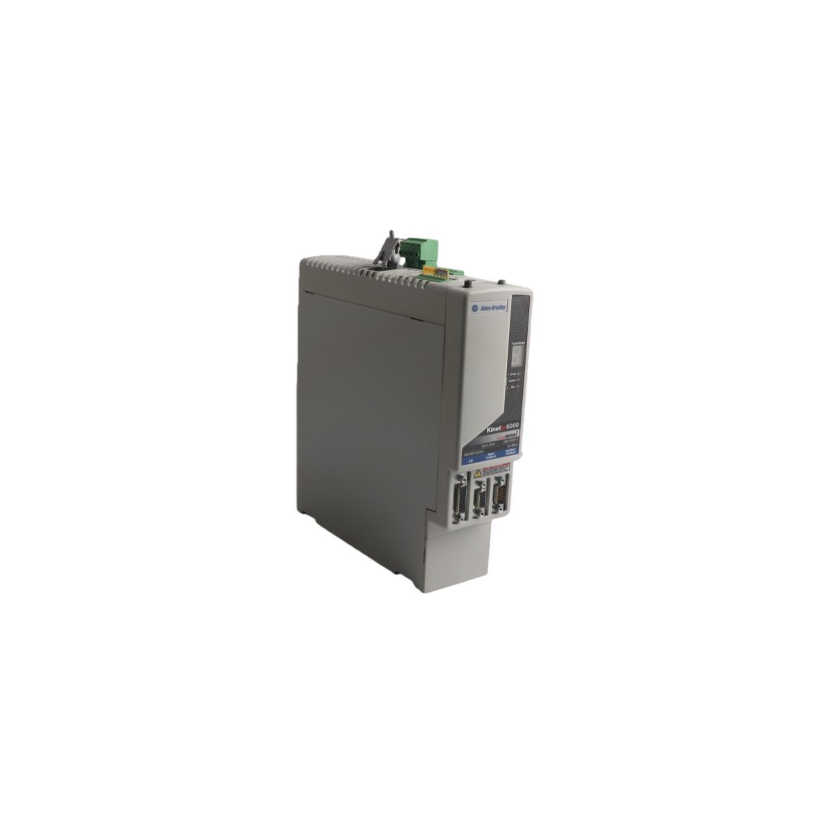
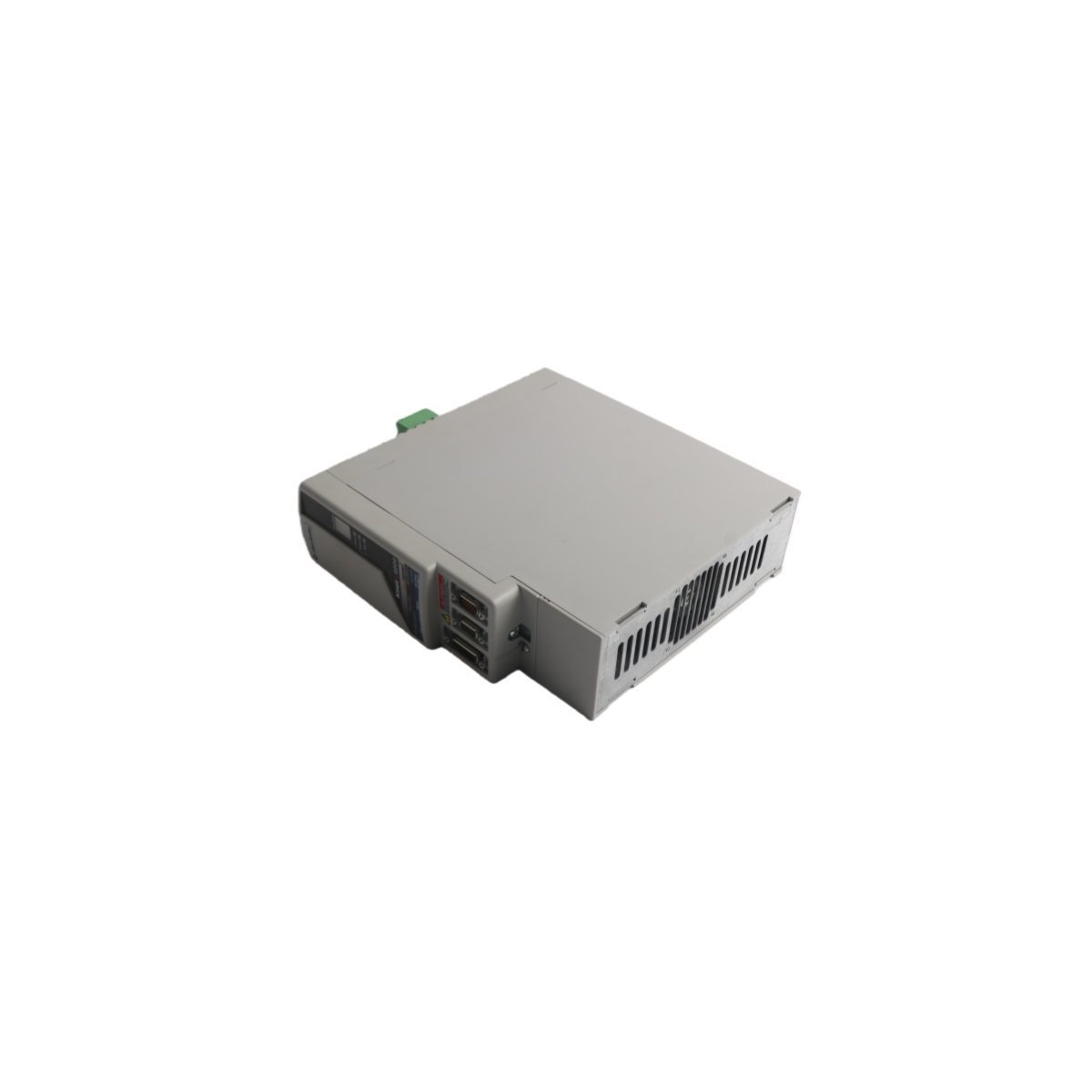
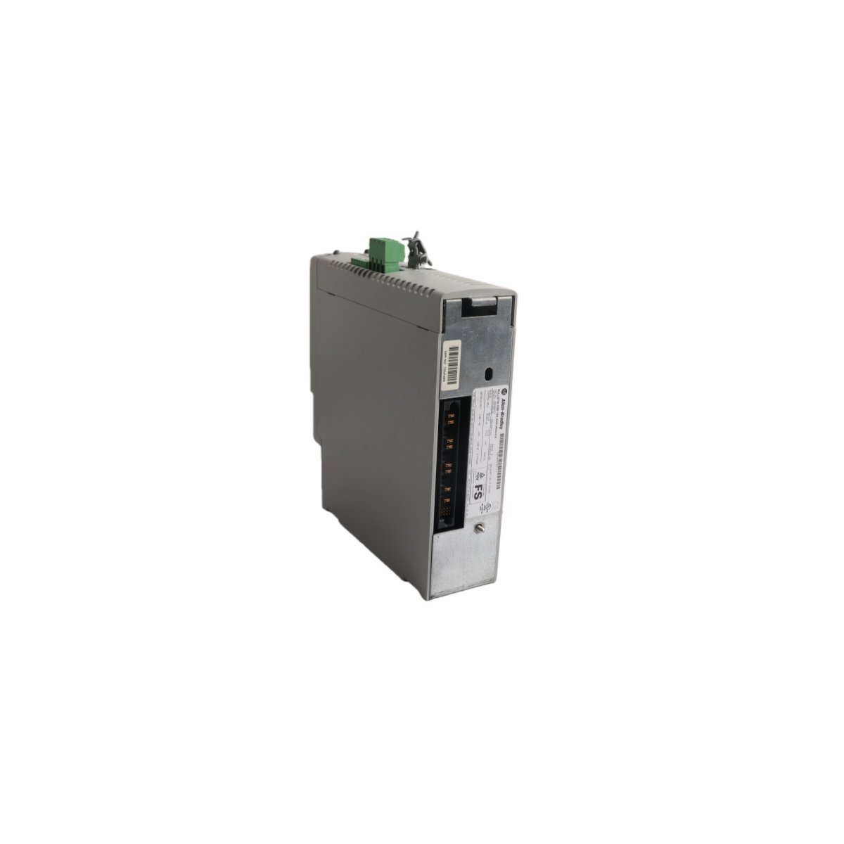
Allen-Bradley 2094-BM02-M single-axis Kinetix inverter module. Brand new original stock, multi-axis system configuration support, and global logistics options.
The Allen-Bradley 2094-BM02-M is a high-performance, single-axis modular inverter section belonging to the Kinetix® 6000, 6200, and 6500 multi-axis servo drive families. Operating on a 460V AC three-phase power rail, this module features a 15A continuous output current rating.
To function as an active motion node, it pairs with interchangeable control modules on an integrated power rail (IAM/AM) system, allowing engineers to transition between SERCOS interface networks or EtherNet/IP deterministic motion networks.
Hardware Specifications
Parameter
Specification
Model Number
2094-BM02-M
Manufacturer
Allen-Bradley / Rockwell Automation
Module Type
Axis Power Module (Inverter Section)
Continuous Current (RMS)
15 A
Peak Current (RMS)
35 A
Input Nominal Voltage
460V AC (Three-Phase via Power Rail)
Weight
0.9 kg
Dimensions
3.5 x 13.0 x 14.5 cm
Status Indicators
Seven-segment diagnostic LED display matrix
Safety Certification
Safe Torque Off (STO) & Safe Speed Monitoring capable
HS Code
8537101190
System Architecture & Power Modularity
The 2094-BM02-M acts strictly as the power stage (inverter) within Rockwell’s modular multi-axis layout. It mounts directly onto a 2094 power rail, which supplies high-voltage DC bus power and internal logic power shared from an Integrated Axis Module (IAM).
By sliding an optional control module (such as a 2094-EN02D-M01-S1 for EtherNet/IP or a 2094-SE02F-M03-S0 for SERCOS) onto the front face of this power module, users gain full control loop processing capabilities alongside integrated advanced safety behaviors.
Frequently Asked Questions
Q: Can the 2094-BM02-M power stage operate independently without a front-facing control module?
A: No. The 2094-BM02-M contains only the high-voltage IGBT inverter block, current sensing circuits, and thermal protection. It has no processing brain or fieldbus port. It must be paired with an appropriate Kinetix control module to operate.
Q: Is this power module compatible with standard Kinetix 6000 systems if an upgrade is needed?
A: Yes, the module can fit into existing Kinetix 6000 rail structures. It allows legacy lines to upgrade their safety or communication profiles simply by swapping out the front-facing control modules without rewiring the underlying high-power infrastructure.
Field Installation & Safety Guidelines
Isolate Power Barriers: Before installation or maintenance, disconnect all primary AC lines feeding the power rail. Wait at least 5 minutes to allow internal DC bus capacitors to fully discharge down to safe residual voltage margins (<50V DC).
Mount on Power Rail: Align the rear alignment hooks of the 2094-BM02-M with the chosen slot on the 2094 power rail. Guide the module backward vertically until its high-power blade connectors engage cleanly with the rail socket.
Secure Hardware Anchors: Fasten the mounting screws at the top and bottom of the module housing to maintain solid thermal grounding against the panel backing.
Attach Control Head: Slide your designated Kinetix network or safety control module onto the front guide pins of the power stage, pushing firmly until the locking tabs snap closed.
Verify Shield Grids: Connect the motor power cable shields to the integrated grounding plate using low-impedance industrial clamps to avoid electromagnetic cross-talk or positioning feedback noise.
The Allen Bradley 81001-450-52-R Power Block Drive, also cataloged as the 81001-450-52-R Power Block Drive, operates as a dedicated hardware component for power distribution and conversion within PLC platform networks.
Hardware Specifications
Parameter
Specification
Model
81001-450-52-R
Brand
Allen Bradley
Origin
USA
Weight
1.14 kg
Dimensions
25 x 20.7 x 5.5 cm
Operating Temp
Standard Industrial Range
Power Consumption
System Dependent
Module Type
Power Block Drive
PLC Deterministic Network Integration
The Allen Bradley 81001-450-52-R utilizes backplane bus communication protocols designed for integration with PLC control architectures. The module supports deterministic network timing, ensuring low-latency power state feedback and synchronization within complex I/O density configurations. Compatibility with field-programmable firmware allows for flash updates to align with evolving backplane bus communication velocity requirements, maintaining bus traffic integrity and reducing collision potential in high-speed control loops.
Frequently Asked Questions
Q: What are the restrictions regarding the installation of the 81001-450-52-R in a redundant power rack?A: Ensure that the backplane bus address is correctly configured to prevent signal collisions. Redundant power configurations must be verified for voltage matching before closing the primary disconnect.Q: Is this module capable of firmware field-upgrades?A: Yes, the unit supports firmware flash compatibility via the primary control bus. Consult the PLC backplane interface documentation for current revision requirements.
Field Installation Guidelines
Mount the module onto a standard metal DIN-rail. Ensure the rail is bonded to the cabinet chassis ground to minimize EMI.
Maintain a minimum clearance of 50 mm above and below the unit to allow for passive thermal heat dissipation.
All power input cabling must utilize shielded twisted-pair conductors to prevent common-mode noise injection into the PLC backplane.
Verify that the 24 VDC output load does not exceed the continuous current rating specified for the associated PLC power bus segment.
Ensure the connector interface is fully seated until a tactile lock is achieved to prevent intermittent contact resistance.
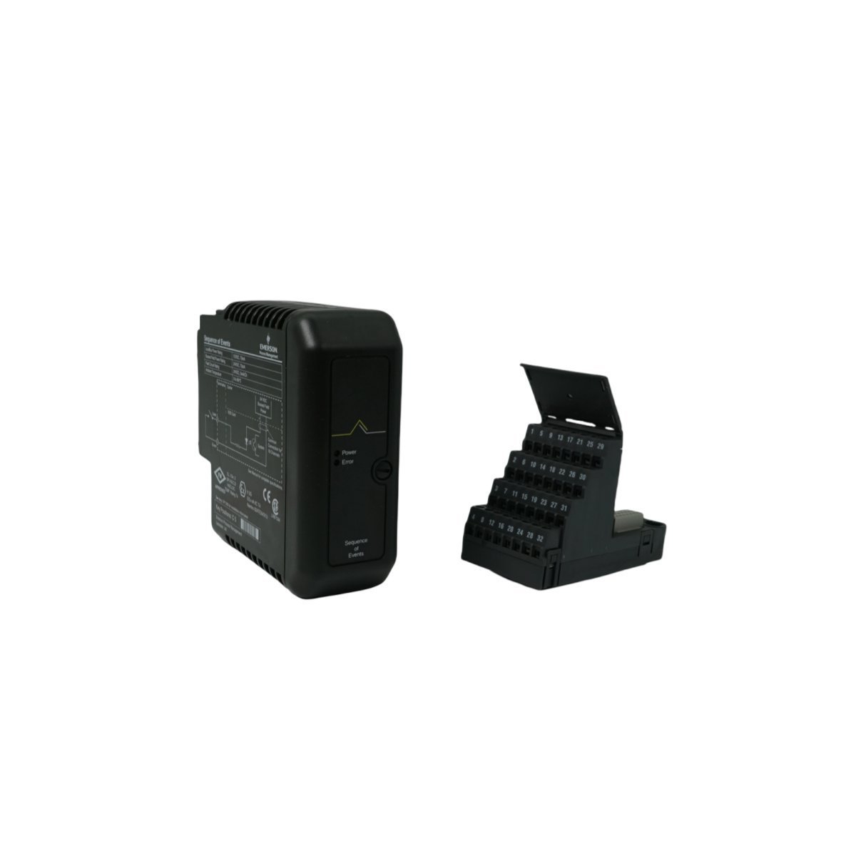
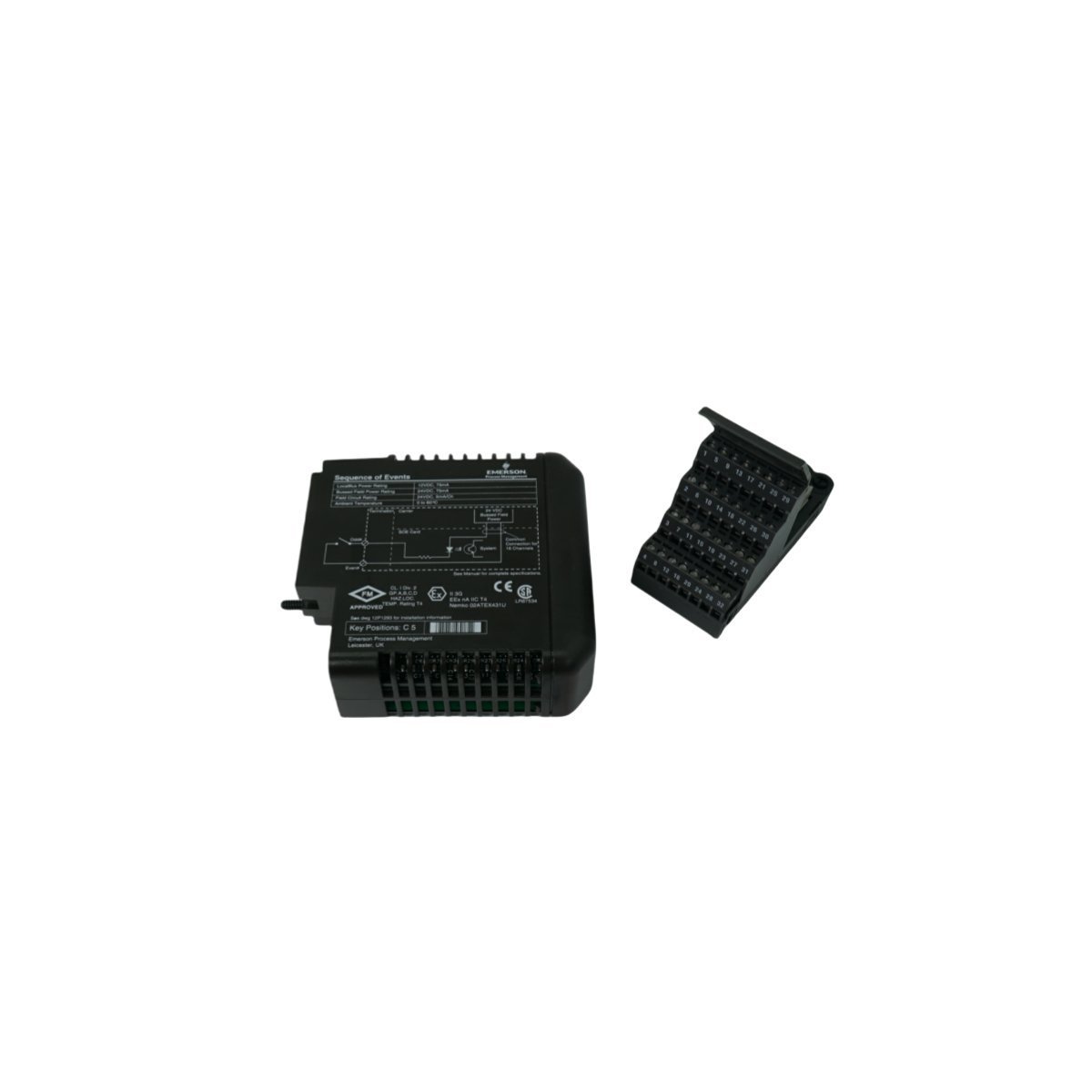
Configured for signal distribution in DeltaV M-series I/O subsystems, the Emerson KJ3222X1-BA1 (KJ3222X1-BA1 Redundant Terminal Block) provides direct physical and electrical execution of field wiring termination for redundant I/O configurations.
Hardware Specifications
Parameter
Specification
Model
KJ3222X1-BA1
Brand
Emerson
Origin
USA
Weight
0.2 kg
Dimensions
4.1 x 12.5 x 10.5 cm
Operating Temp
Standard Industrial Range
Power Consumption
Passive Component
Compatibility
DeltaV M-series I/O
DeltaV DCS Process Control Characteristics
The terminal block facilitates the implementation of 4-20 mA HART loop protocol architectures by providing physical connection points for redundant I/O card pairs. It maintains channel-to-channel isolation through optimized PCB routing, preventing cross-talk between high-density loops. The mechanical design ensures cold junction compensation (CJC) stability when integrated with thermocouple input channels. By utilizing the redundant terminal architecture, the system maintains continuous signal integrity for critical control loops, allowing for maintenance operations on one I/O module without disrupting the current loop of the secondary redundant partner.
Frequently Asked Questions
Q: Does the KJ3222X1-BA1 support active electronic components?A: No, this is a passive terminal block. It serves as an interface between field wiring and the DeltaV I/O carrier, routing signals to the redundant I/O module pair.Q: Can this terminal block be used for non-redundant I/O configurations?A: While designed for redundancy, the terminal block provides the physical interface required for specific DeltaV M-series modules. Compatibility must be verified against the specific I/O module part number (VE4033S2B1) to ensure pin mapping alignment.
Field Installation Guidelines
Prior to wiring, verify that the I/O carrier power is disconnected to prevent accidental contact with energized field circuits.
During installation, align the terminal block with the mating connectors on the DeltaV I/O carrier, ensuring the guide pins are fully seated before tightening the retention screws.
When connecting field devices, ensure that shielded, twisted-pair cabling is utilized for all 4-20 mA loops to mitigate electromagnetic interference.
Upon securing the wiring, verify the continuity of the redundant paths using a digital multimeter at the terminal points before initiating loop commissioning.
Maintain appropriate physical separation between the terminal block wiring and any high-voltage AC lines to prevent induced noise on the analog signal loops.
The Allen-Bradley 2094-BC01-M01-S, also cataloged as the 2094-BC01-M01-S Integrated Axis Module, operates as a dedicated hardware component for high-speed motion control and power regulation within Kinetix 6000 multi-axis drive platforms.
Hardware Specifications
Parameter
Specification
Model
2094-BC01-M01-S
Brand
Allen-Bradley
Origin
USA
Weight
0.9 kg
Dimensions
3.5 cm x 13 cm x 14.5 cm
Operating Temp
Standard industrial range
Power Consumption
3.9 kW (Total)
Inverter Current
9 A
Input Voltage
360-480 V AC
PLC and Drive Control Characteristics
The 2094-BC01-M01-S incorporates backplane bus communication velocity protocols, enabling deterministic synchronization between the converter and inverter stages. The architecture facilitates I/O density scaling within the drive cabinet, allowing for coordinated power distribution across multiple integrated axes. Furthermore, the module supports firmware flash compatibility, which ensures that internal logic remains aligned with system-wide motion control requirements. This design enables precise control over power threshold excursions and maintains stable torque output during transient loading conditions.
Frequently Asked Questions (FAQ)
Q: What are the primary communication requirements for the SERCOS interface on this module?A: The SERCOS interface requires fiber optic media configured in either linear or ring topologies; ensure that the fiber ends are polished and properly seated in the transceivers to maintain signal integrity and avoid communication latency.Q: Can the Safe Torque Off (STO) function be bypassed if not required by the application?A: The STO circuit must remain closed via the designated safety input terminals to enable drive operation; if the safety function is not utilized, you must jumper these inputs according to the installation manual to permit the pulse-width modulation (PWM) output to the motor.
Field Installation Guidelines
To begin with, ensure all primary power is disconnected and the DC bus capacitors have reached a discharge state before you mount the module onto the power rail;Â subsequently, verify that the rear-facing power connectors align correctly to prevent pin deformation.
Furthermore, terminate all motor feedback cables using the appropriate shielded connectors;Â in addition, ensure the shield drain wire connects to the designated ground lug to minimize electromagnetic interference (EMI).
When configuring the SERCOS ring, route fiber optic cables with a sufficient bend radius to prevent signal attenuation;Â meanwhile, label each fiber connection to identify the transmit (Tx) and receive (Rx) paths clearly.
Finally, verify the input voltage range (360-480 V AC) matches the site supply before you apply power;Â by doing so, you ensure the internal power conversion stage functions within rated limits.
The GE 750-P5-G5-HI-A20-R is a robust Multilin feeder management relay featuring dual-processor architecture for precise protection and monitoring. This panel-mount device offers comprehensive metering, oscillography, and communication capabilities for critical distribution systems.
The GE DS200TCEAG1BTF is a dedicated Emergency Overspeed Board for the Mark V turbine control system. It features an integrated microprocessor and hardware-based protection to monitor turbine velocity and execute critical safety trip functions reliably.
The GE IS200TDBSH2A is a Mark VI discrete simplex terminal board designed for turbine control systems. It provides 96 robust connection points for efficient signal management.
The Allen-Bradley 1769-ECR is a right-side bus termination end cap for CompactLogix and MicroLogix 1500 systems. It terminates the integrated FlexBus backplane to ensure signal integrity, prevent communication packet reflection, and maintain stable PLC operations.
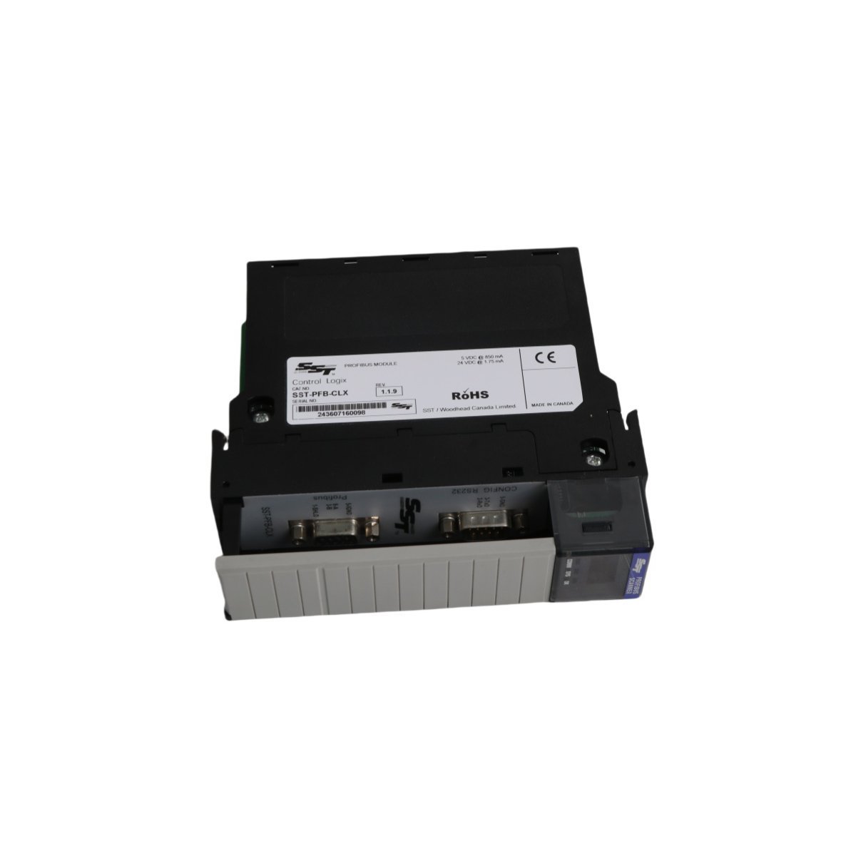
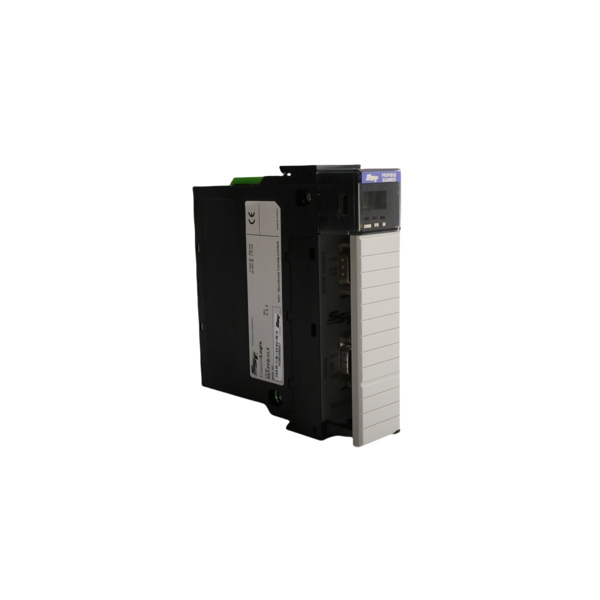
The Allen-Bradley SST-PFB-CLX is a ControlLogix PROFIBUS DP Master Scanner module that provides seamless integration between Rockwell controllers and PROFIBUS networks. It supports up to 12 Mbps data rates and features a dedicated configuration port for easy system setup.
The GE Fanuc IC670CHS002 is a high-performance terminal block for Field Control systems. It features isolated common groups (A, B, and E) for flexible power distribution and a modular design that allows for I/O module replacement without disconnecting field wiring.
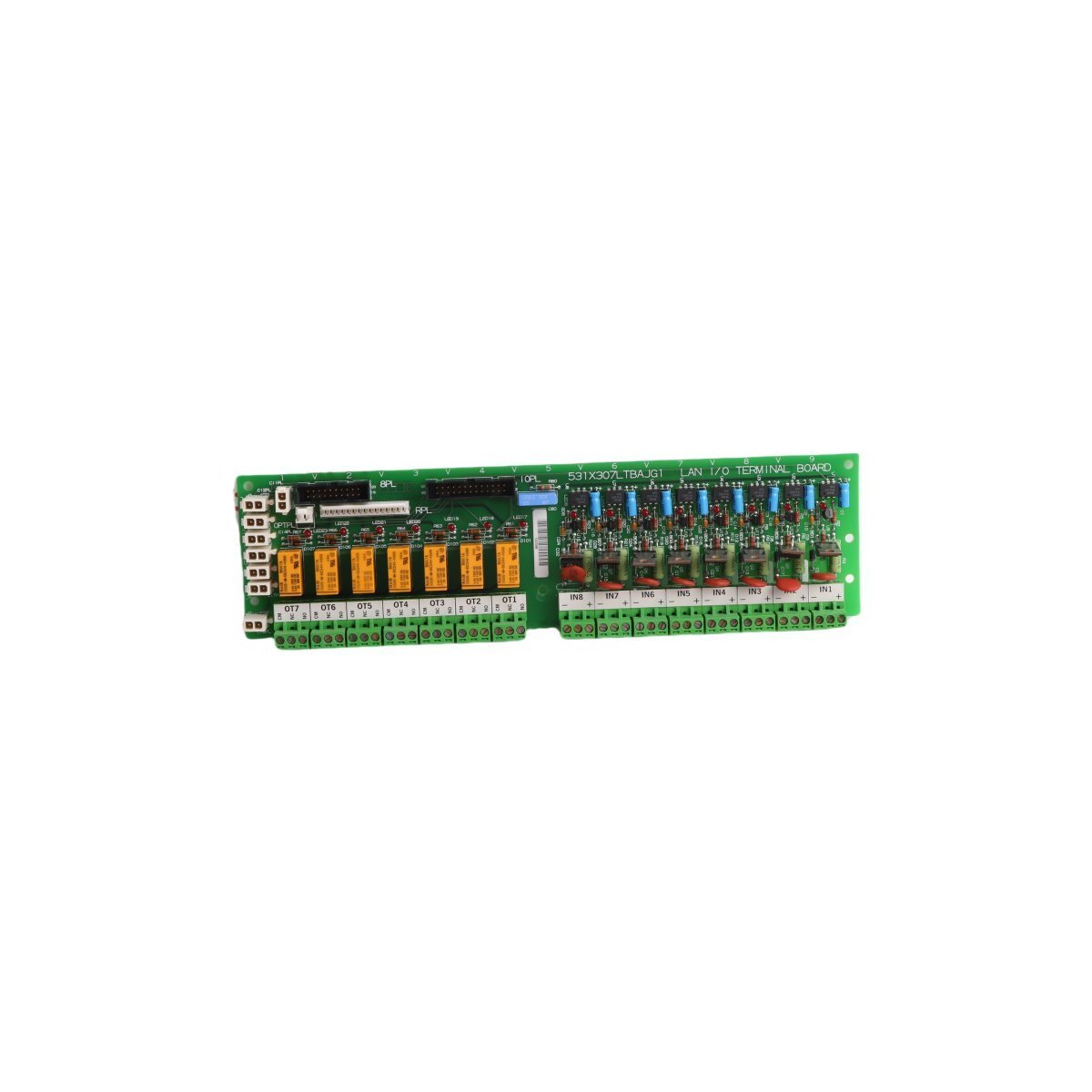
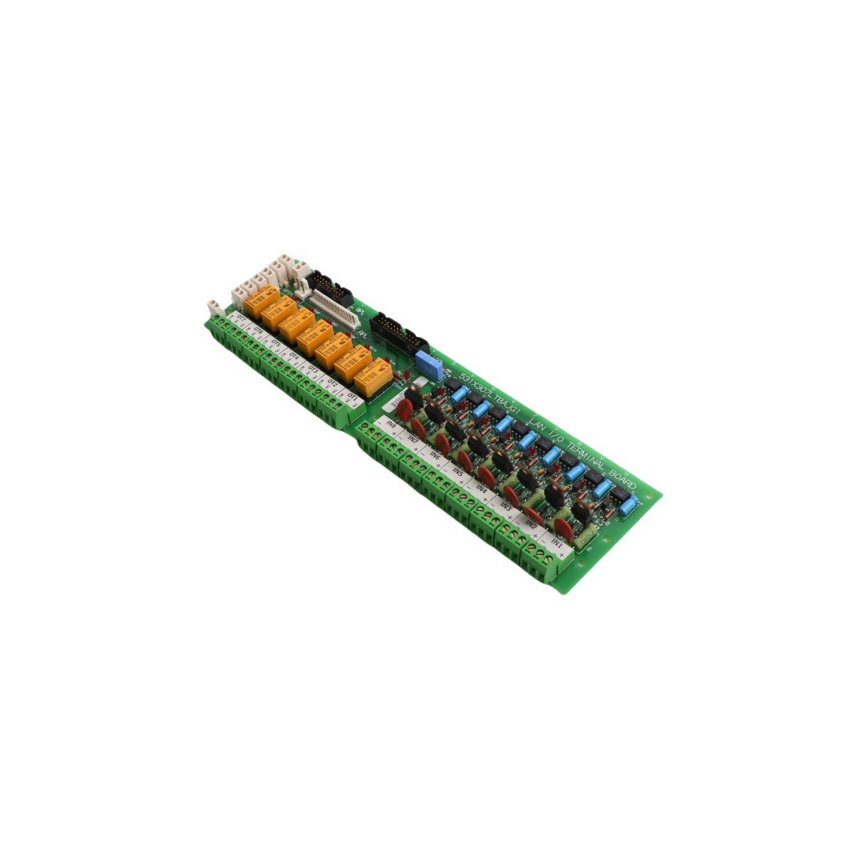
The GE 531X307LTBAKG1 is a Multilin series I/O Terminal Board designed for high-precision signal processing in GE drive systems. It supports RS-422 communication, encoder feedback, and features configurable hardware settings for specialized industrial automation tasks.
The ICS Triplex T8293C is a high-integrity Power Distribution Unit for the Trusted TMR system. It provides redundant 24 VDC power management, advanced branch circuit monitoring, and active short-circuit protection, ensuring continuous uptime and SIL 3 safety compliance for critical industrial controllers.
The ICS Triplex T8311 is a high-reliability Expander Interface for the Trusted TMR system. It enables secure I/O bus expansion across multiple chassis, featuring a durable aluminum housing, high-speed data synchronization, and full fault-tolerant compatibility for SIL 3 safety applications.
We are committed to protecting your privacy. The information collected here is strictly used to provide the requested quotes, technical support, and relevant industrial automation solutions.