
Sale!
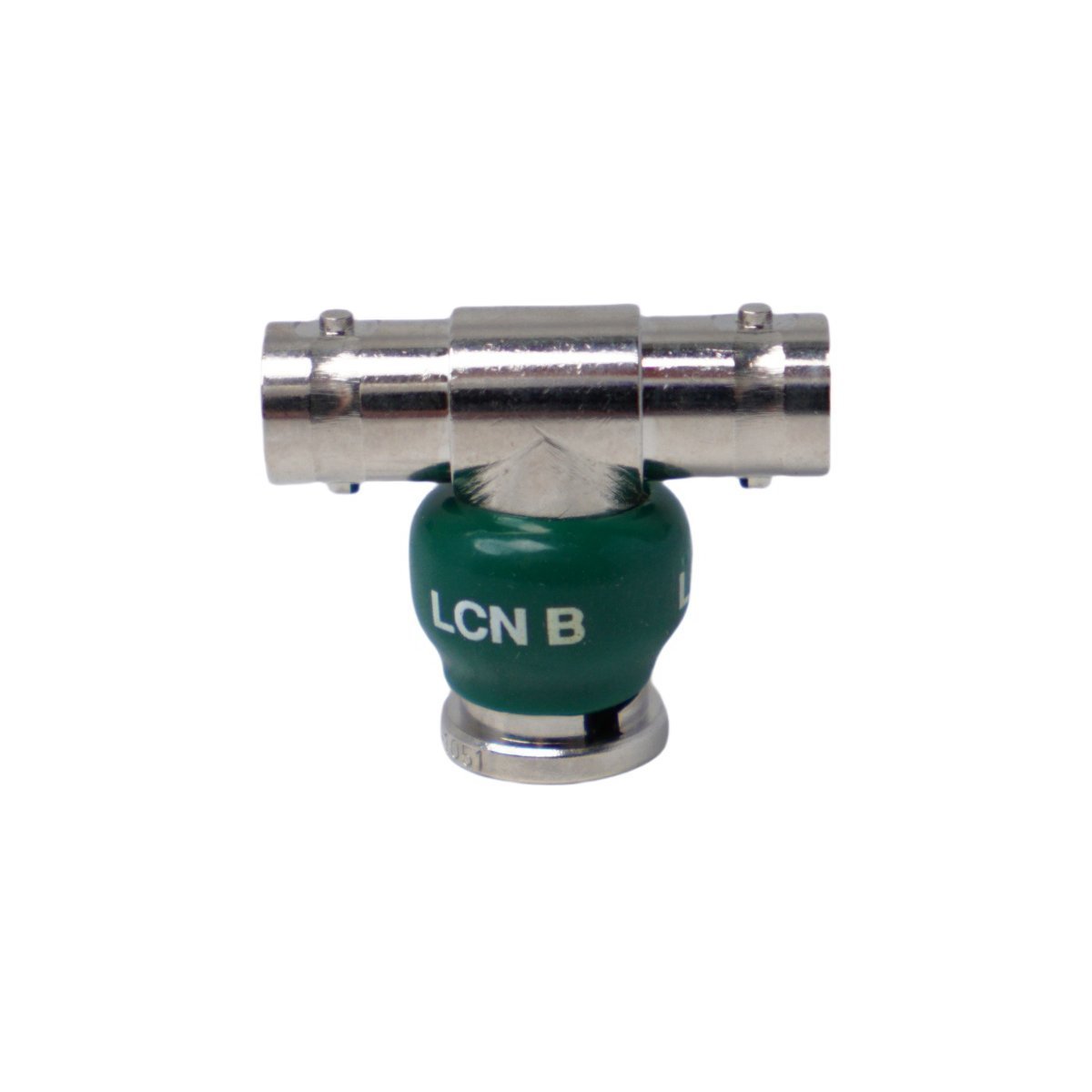
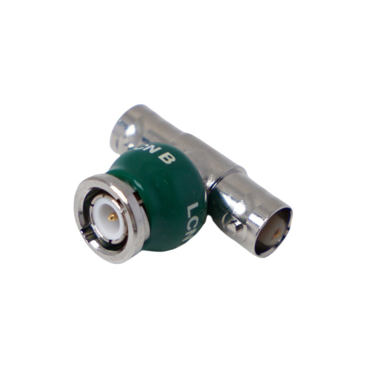
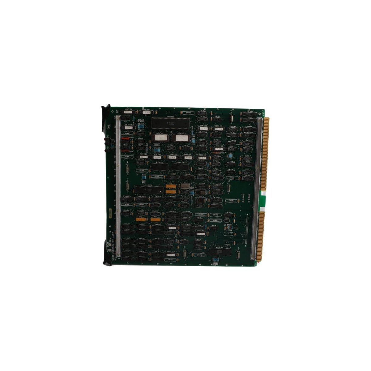
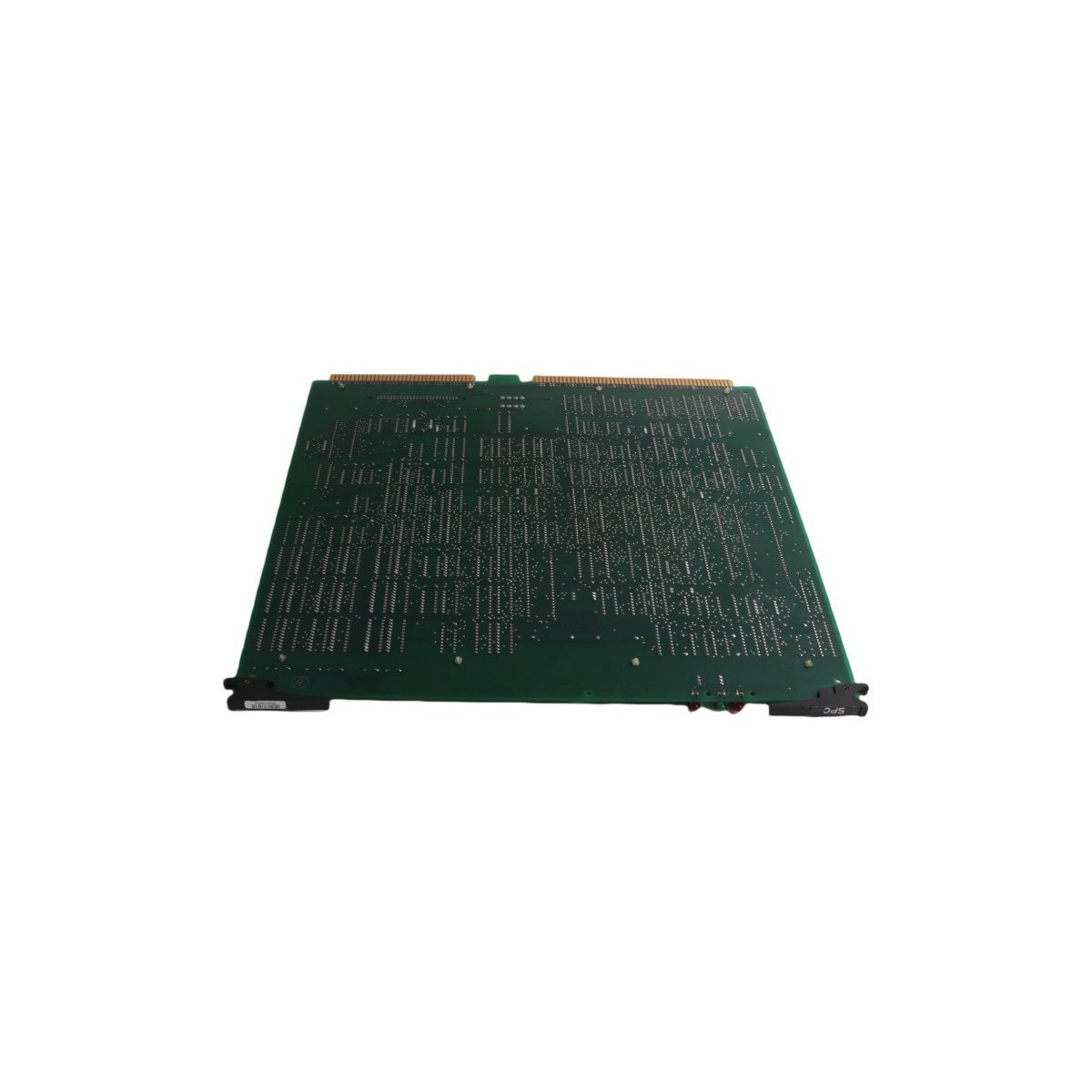
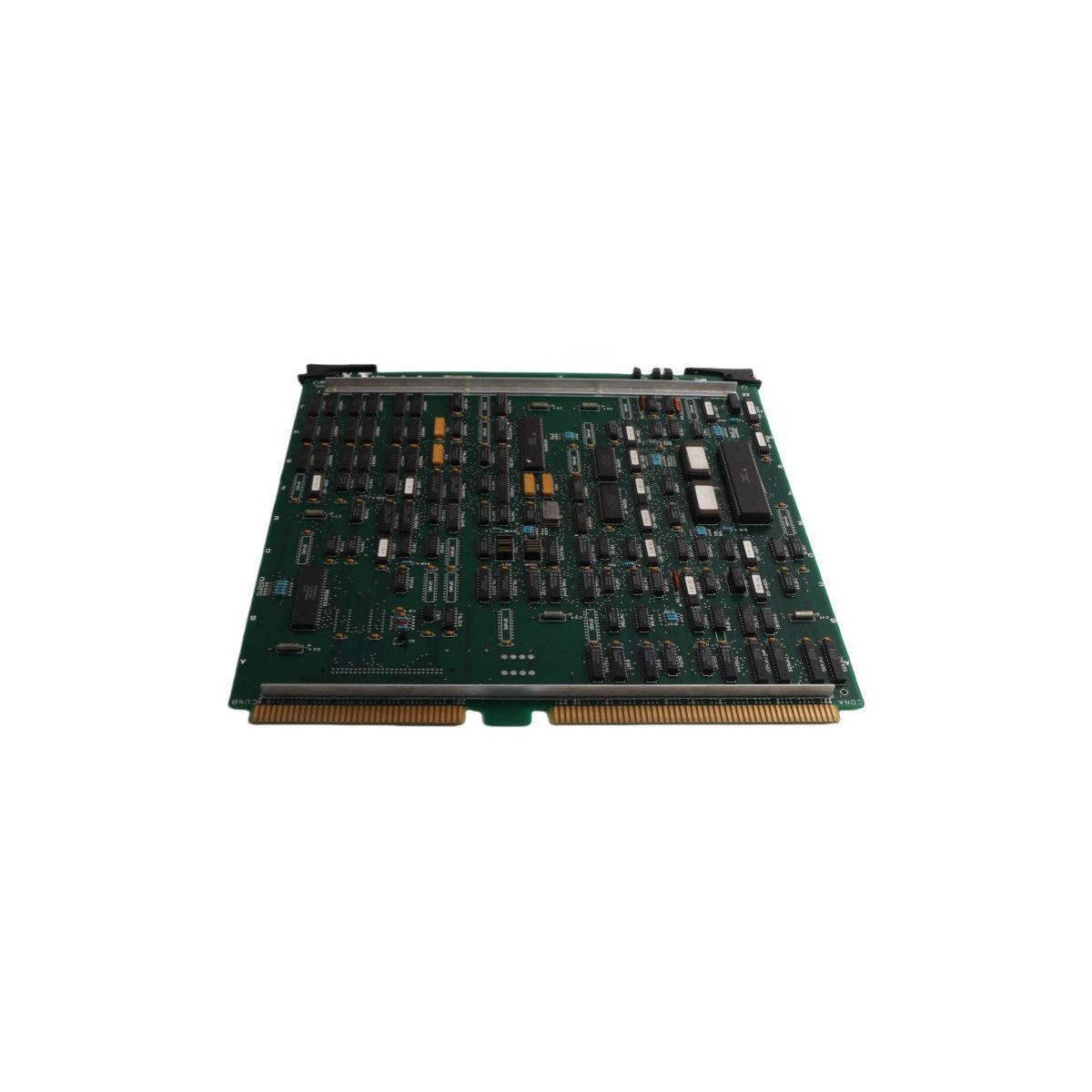
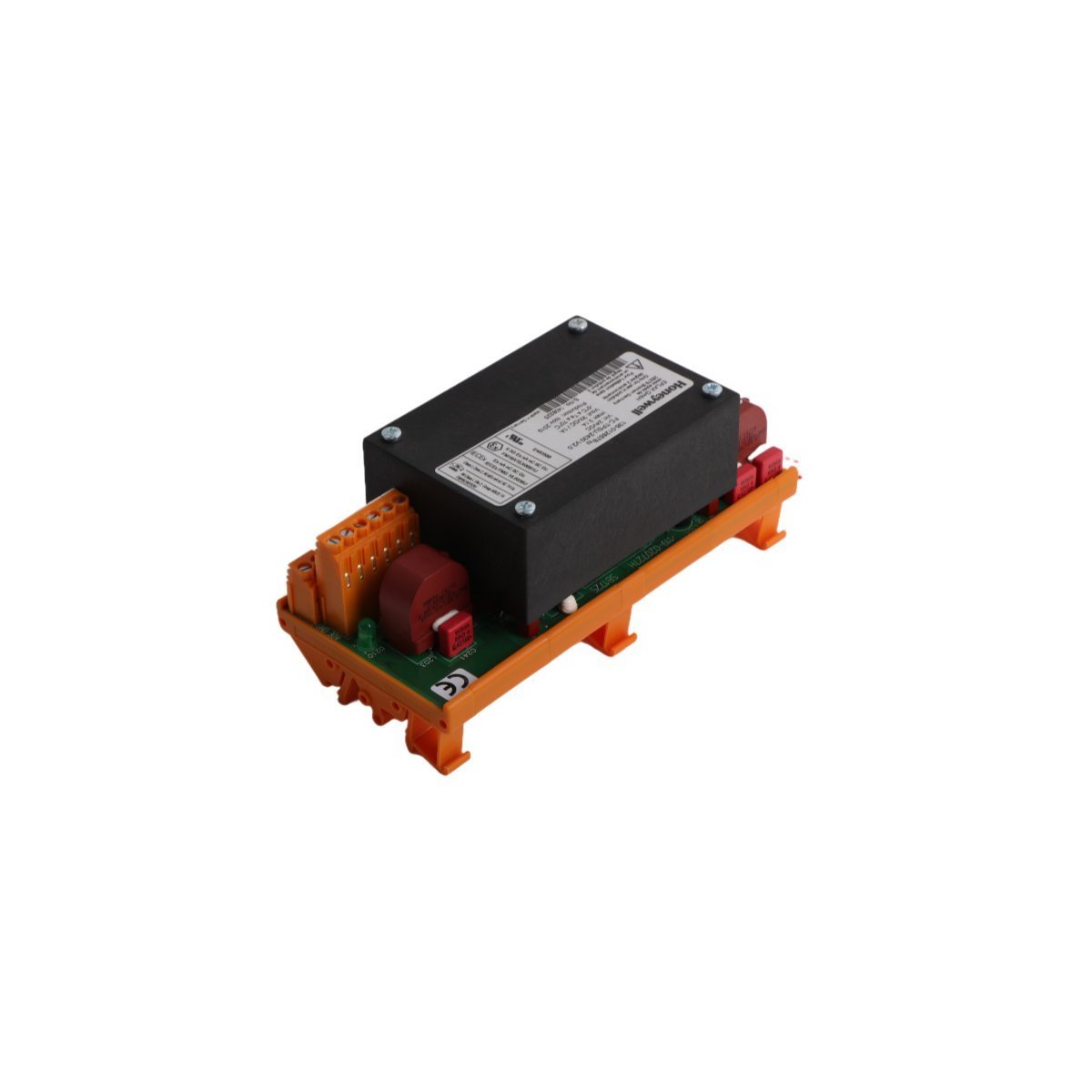
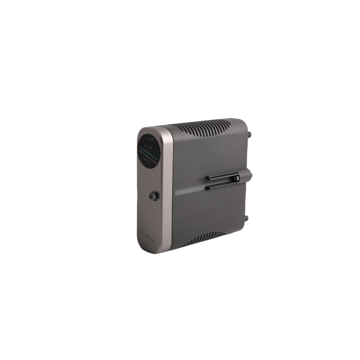
Honeywell 51196041-100 Experion PKS Panel Accessory
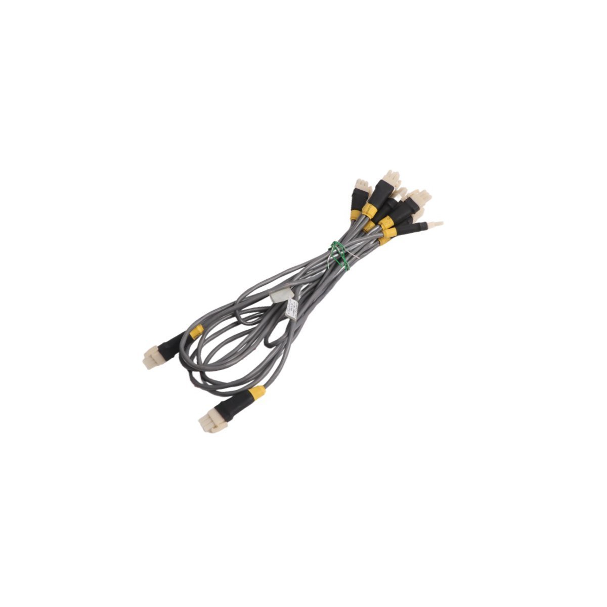
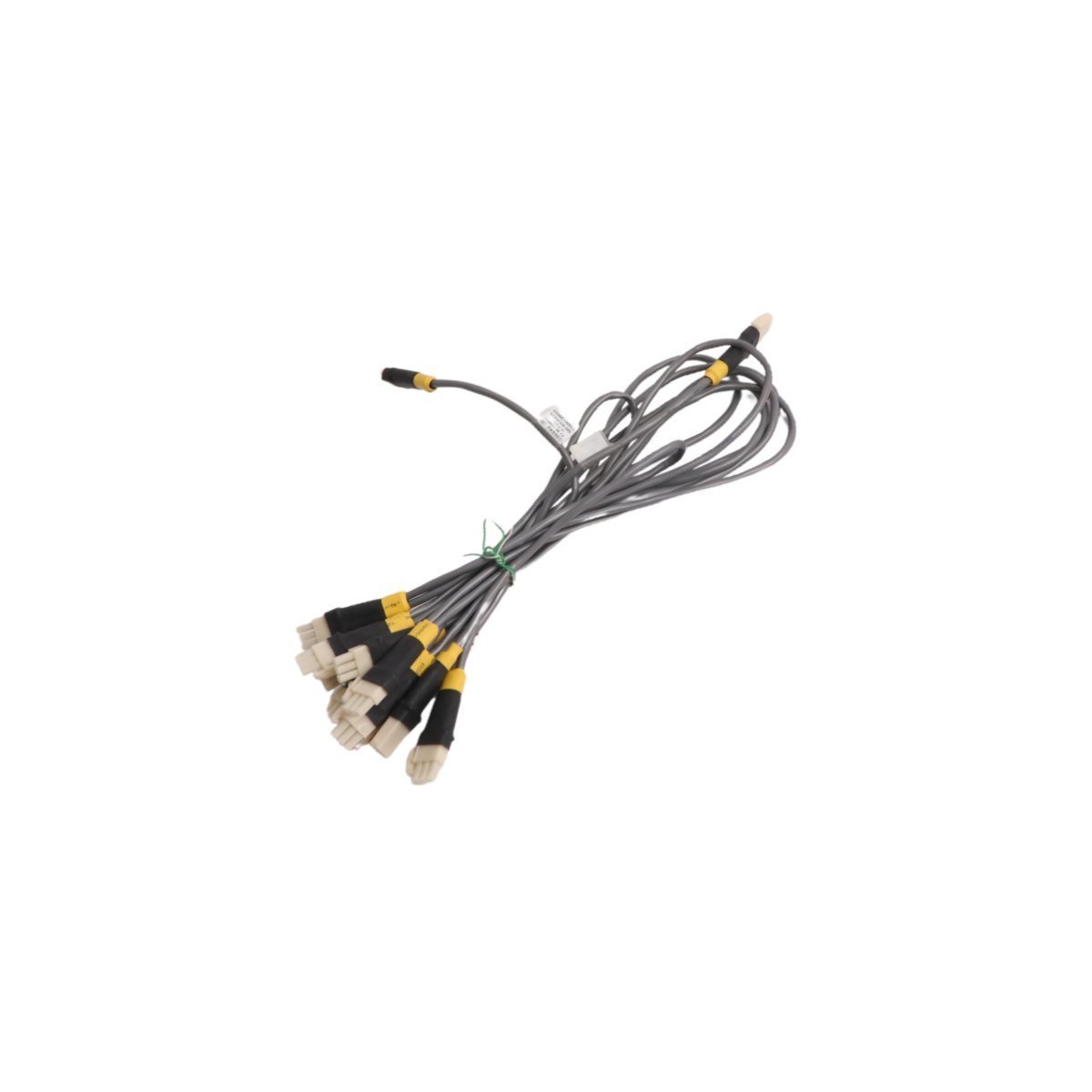
Honeywell 51196041-100 Experion PKS Panel Accessory component. Brand New, Original Stock, Global Shipping. High-precision technical specs and field guidelines.
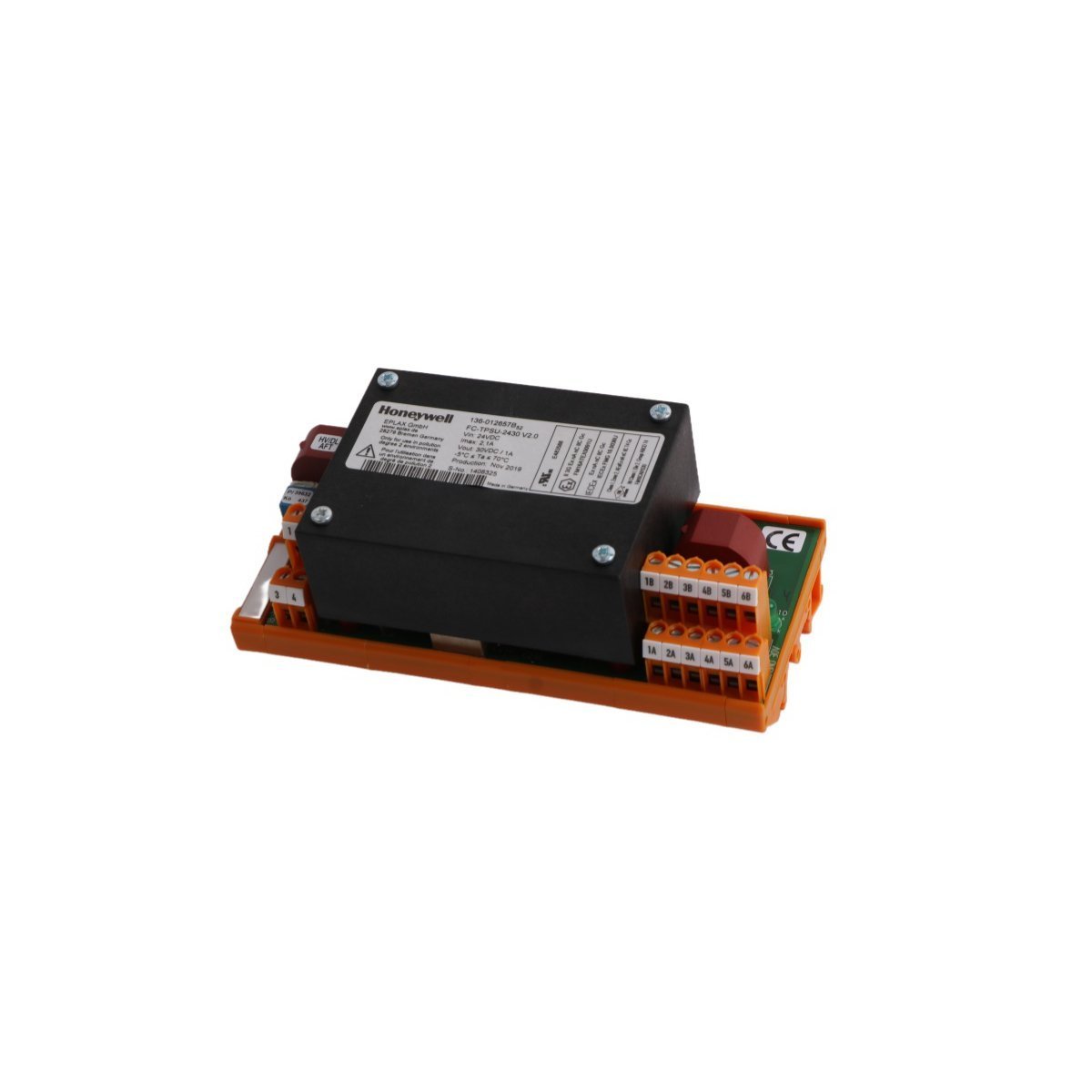
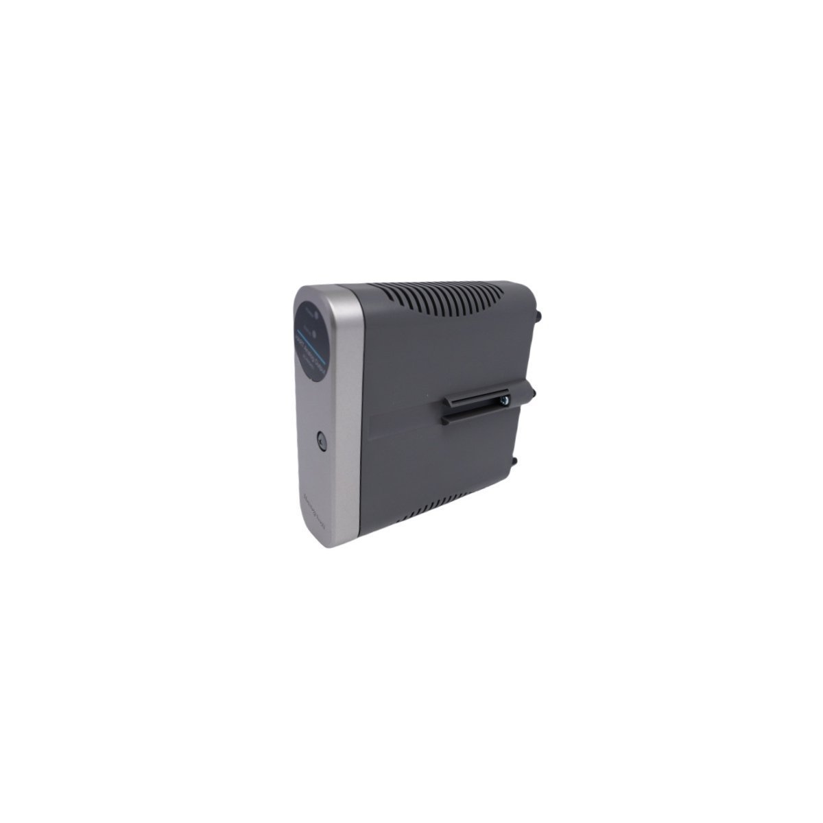
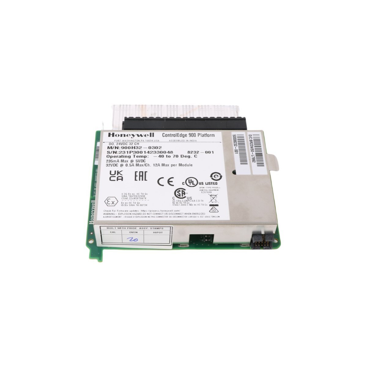
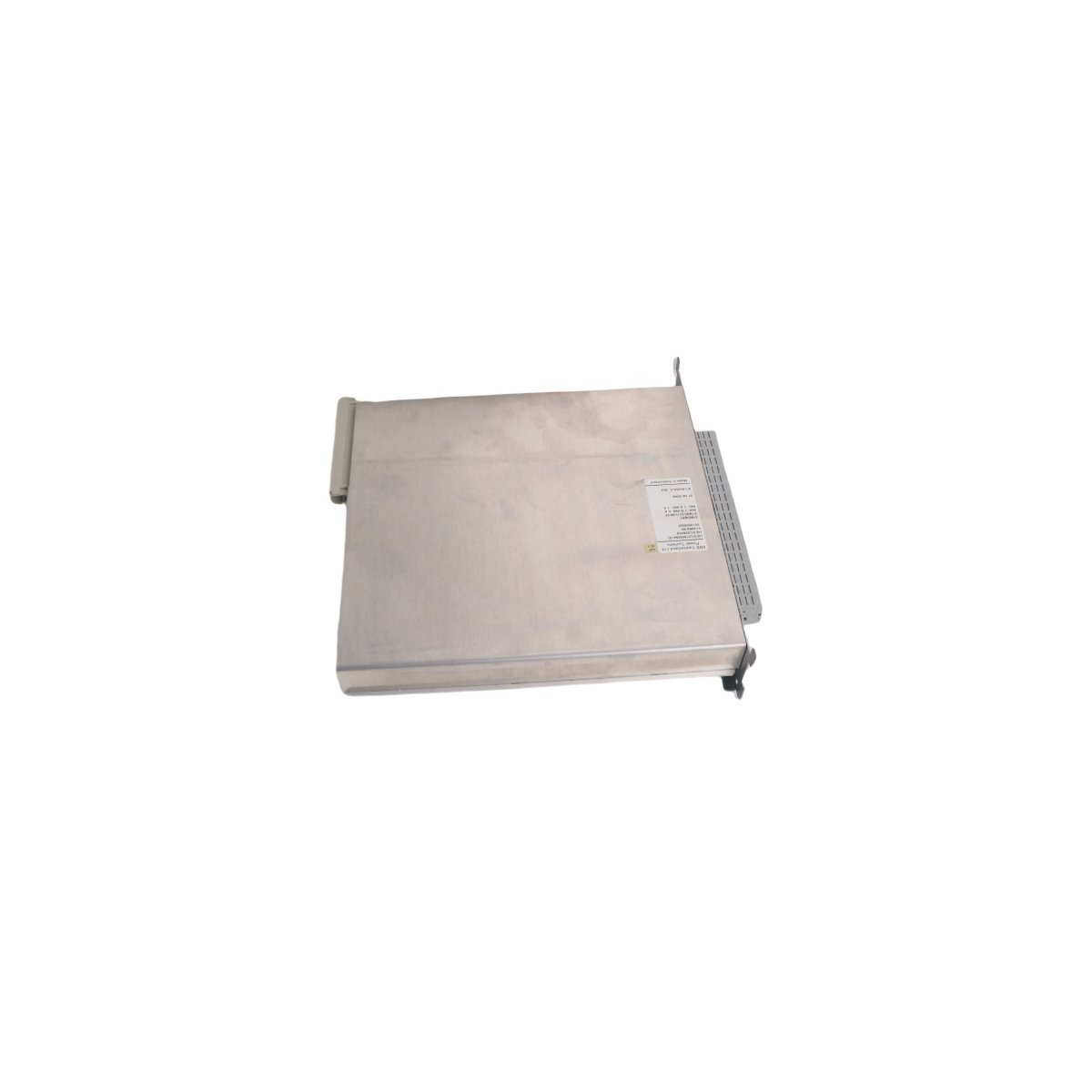
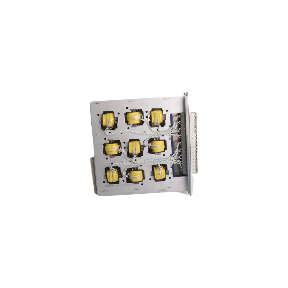
The Honeywell 51401052-100, also cataloged as the 51401052-100 Control Board, operates as a dedicated hardware component for peripheral process signaling and interface management within Experion PKS platforms.
| Parameter | Specification |
|---|---|
| Model | 51401052-100 |
| Brand | Honeywell |
| Origin | USA |
| Weight | 0.84 kg |
| Dimensions | 36.6 x 36.4 x 1.5 cm |
| Operating Temp | Industrial standard |
| Power Consumption | Backplane dependent |
The Honeywell 51401052-100 facilitates direct communication between the primary control processor and field-level peripherals. The board incorporates 4-20 mA HART loop protocol support to enable continuous data exchange with intelligent field transmitters. To maintain signal integrity across complex I/O topologies, the design utilizes channel-to-channel isolation, effectively mitigating common-mode noise and ground loop interference. Additionally, the assembly features integrated cold junction compensation (CJC) for high-accuracy temperature measurements when utilized with thermocouple-based input channels.
Q: Does the 51401052-100 board support hot-swapping under normal operational loads?
A: Hot-swapping is permitted only if the specific I/O rack configuration and firmware version support online insertion and removal (OIR) and the associated process segment has been placed in a manual or safe state.
Q: Are there specific firmware flash requirements for this board?
A: The board requires firmware compatibility with the host controller’s revision level; verify the Experion PKS system compatibility matrix before initiating any firmware updates.





We are committed to protecting your privacy. The information collected here is strictly used to provide the requested quotes, technical support, and relevant industrial automation solutions.