You are here:
SKU: FC1000B1001

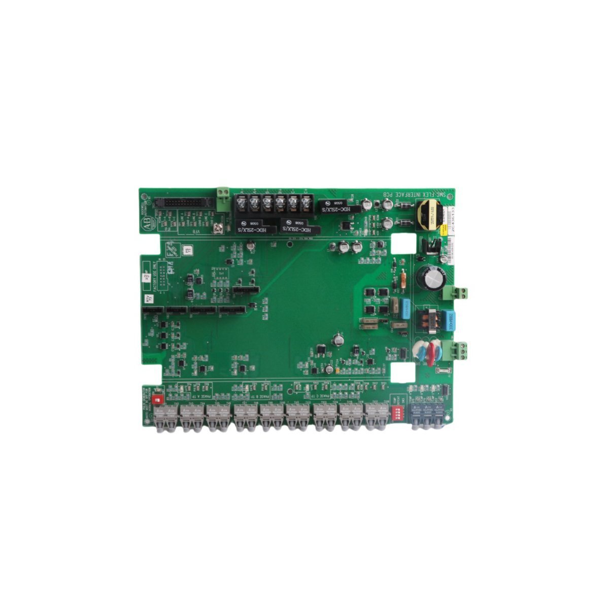
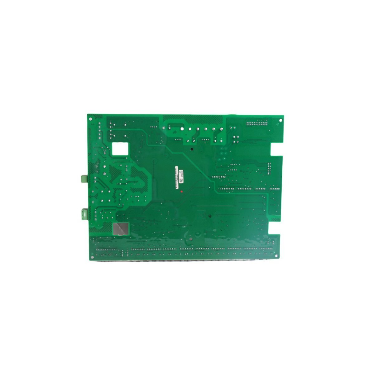
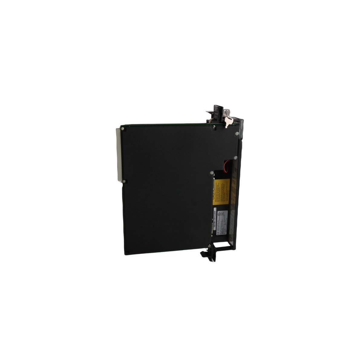
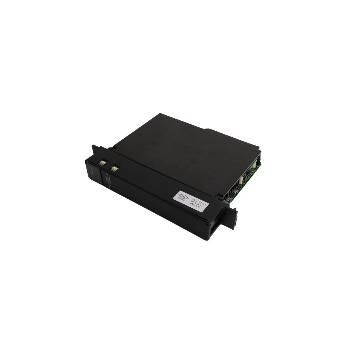
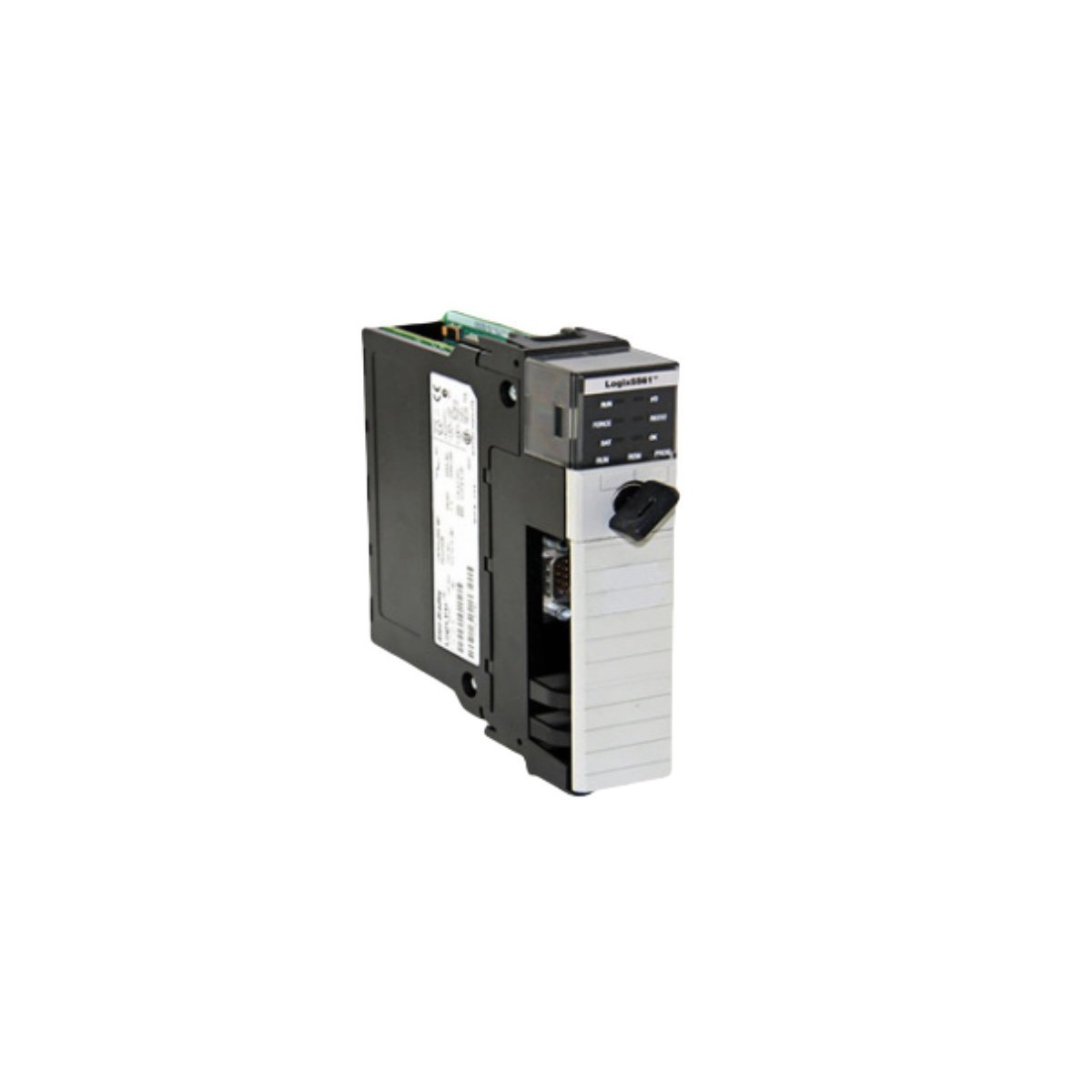
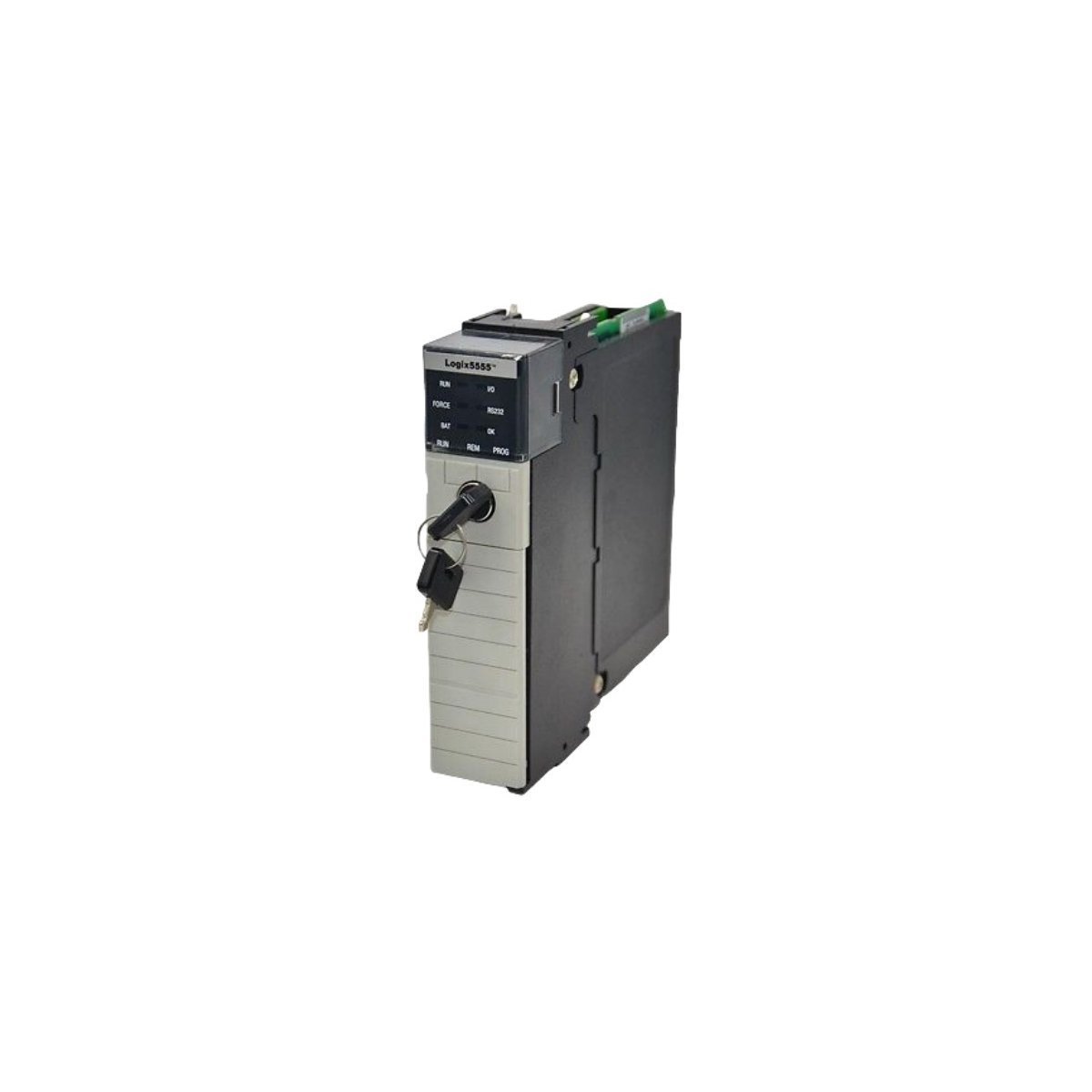
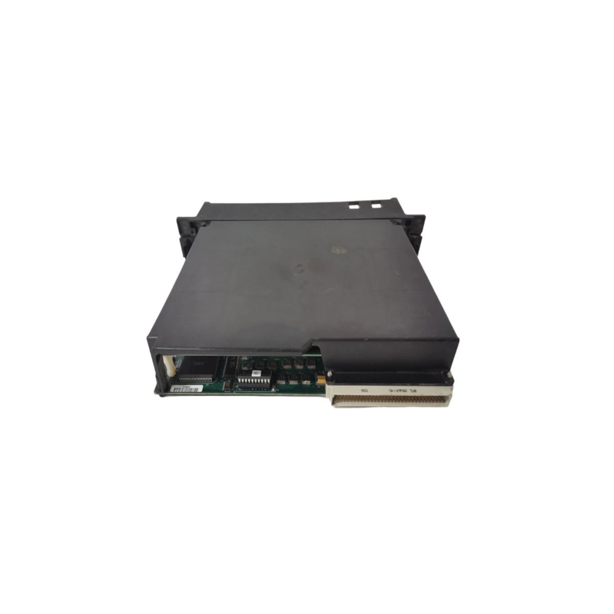
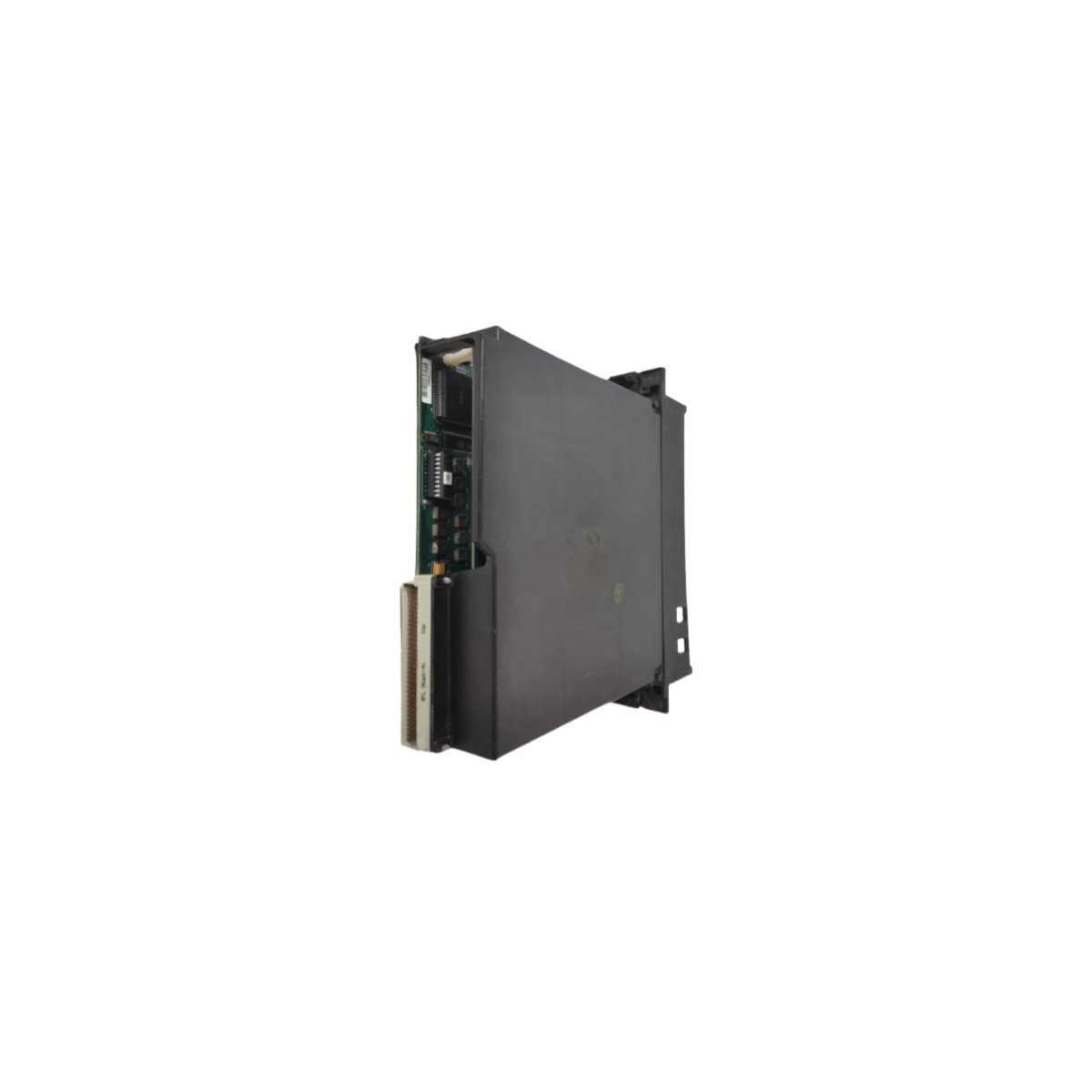
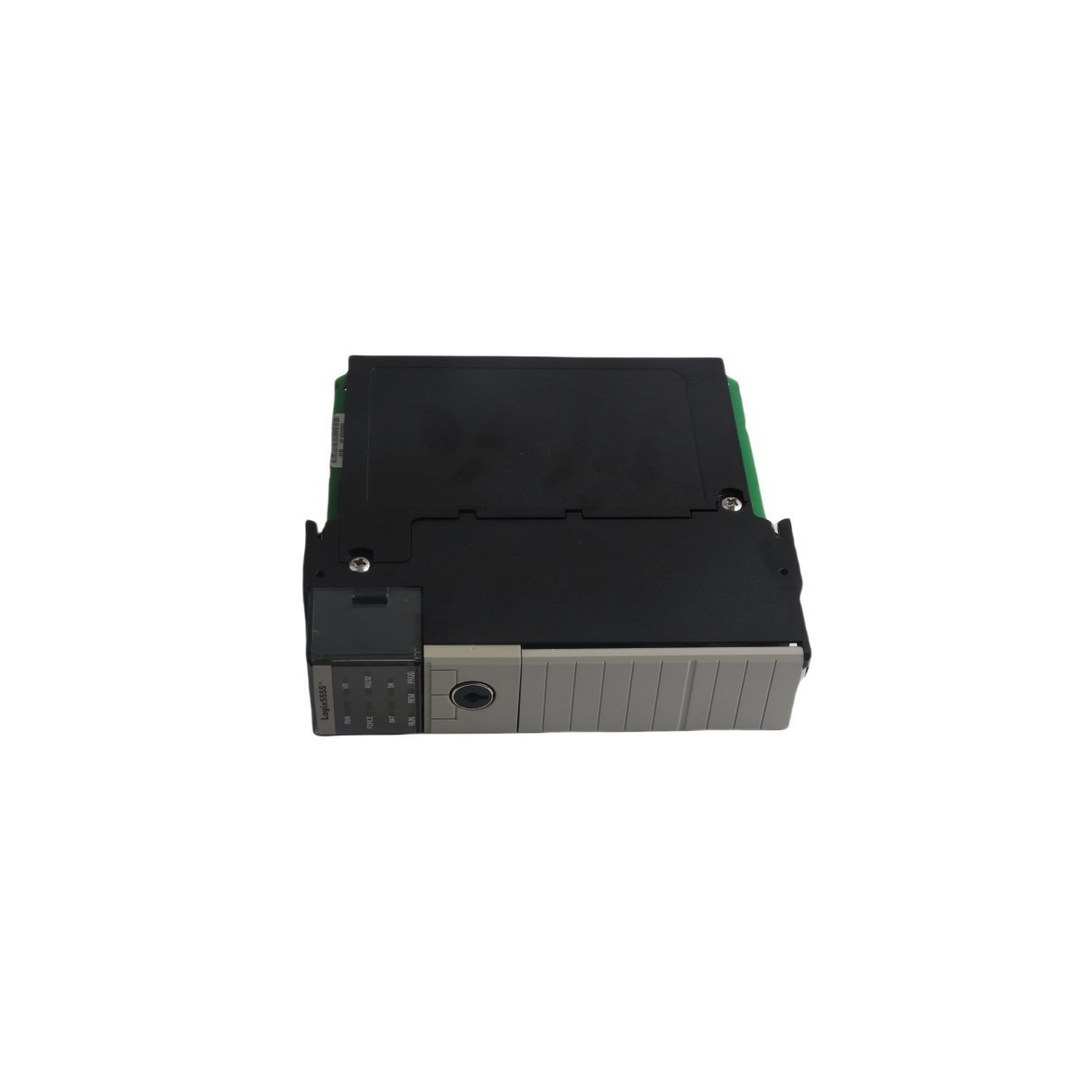
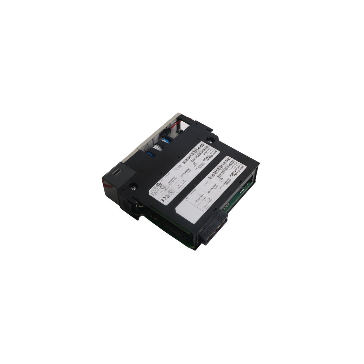
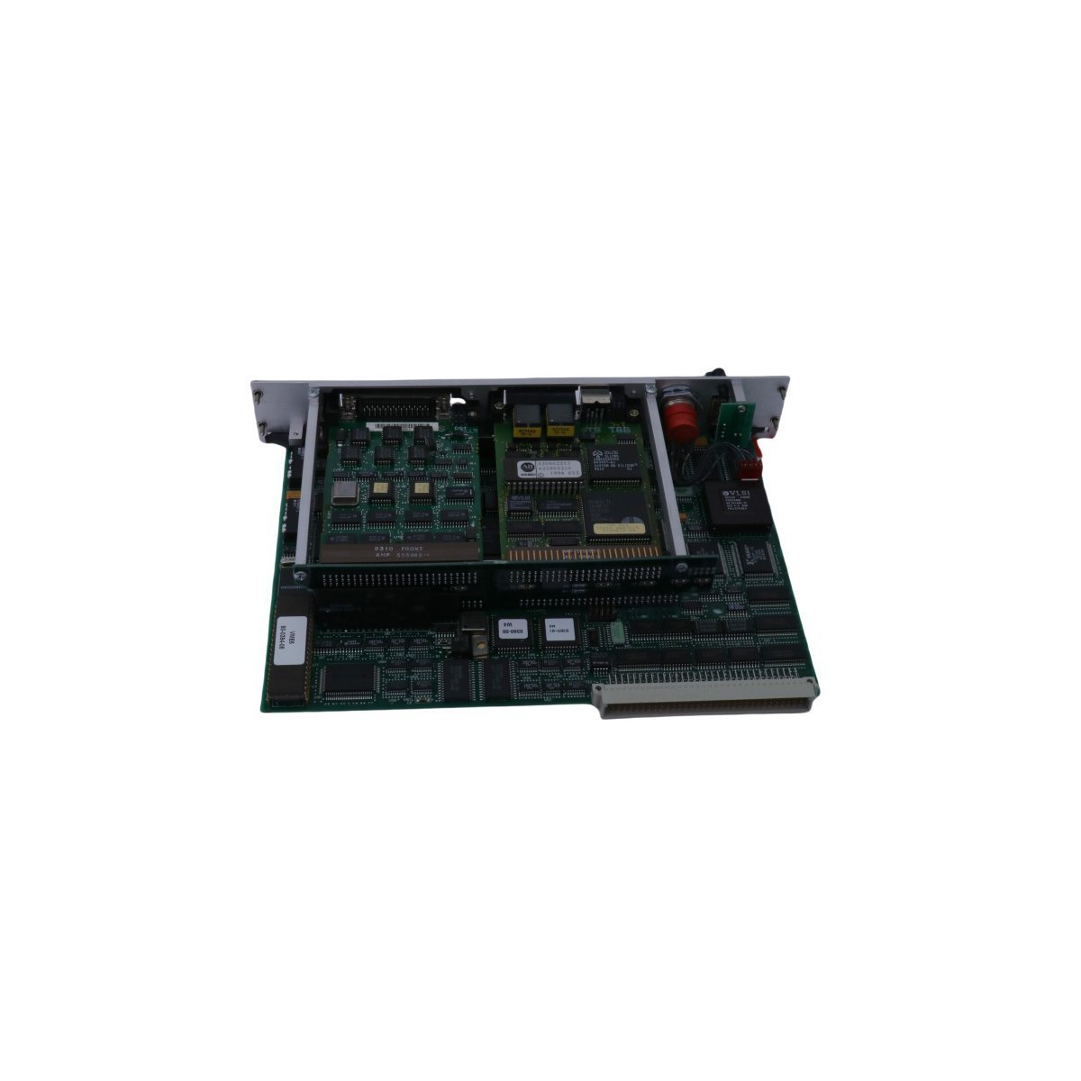
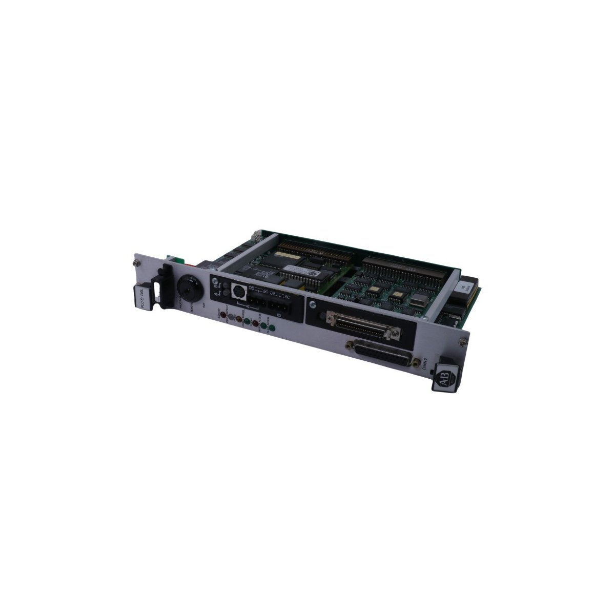
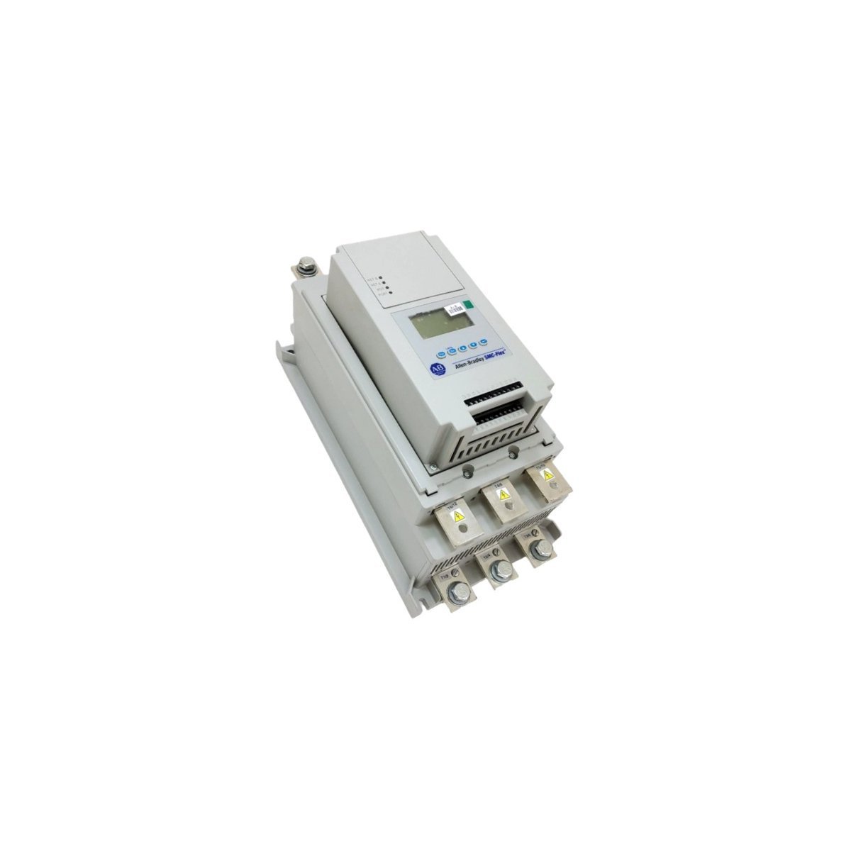
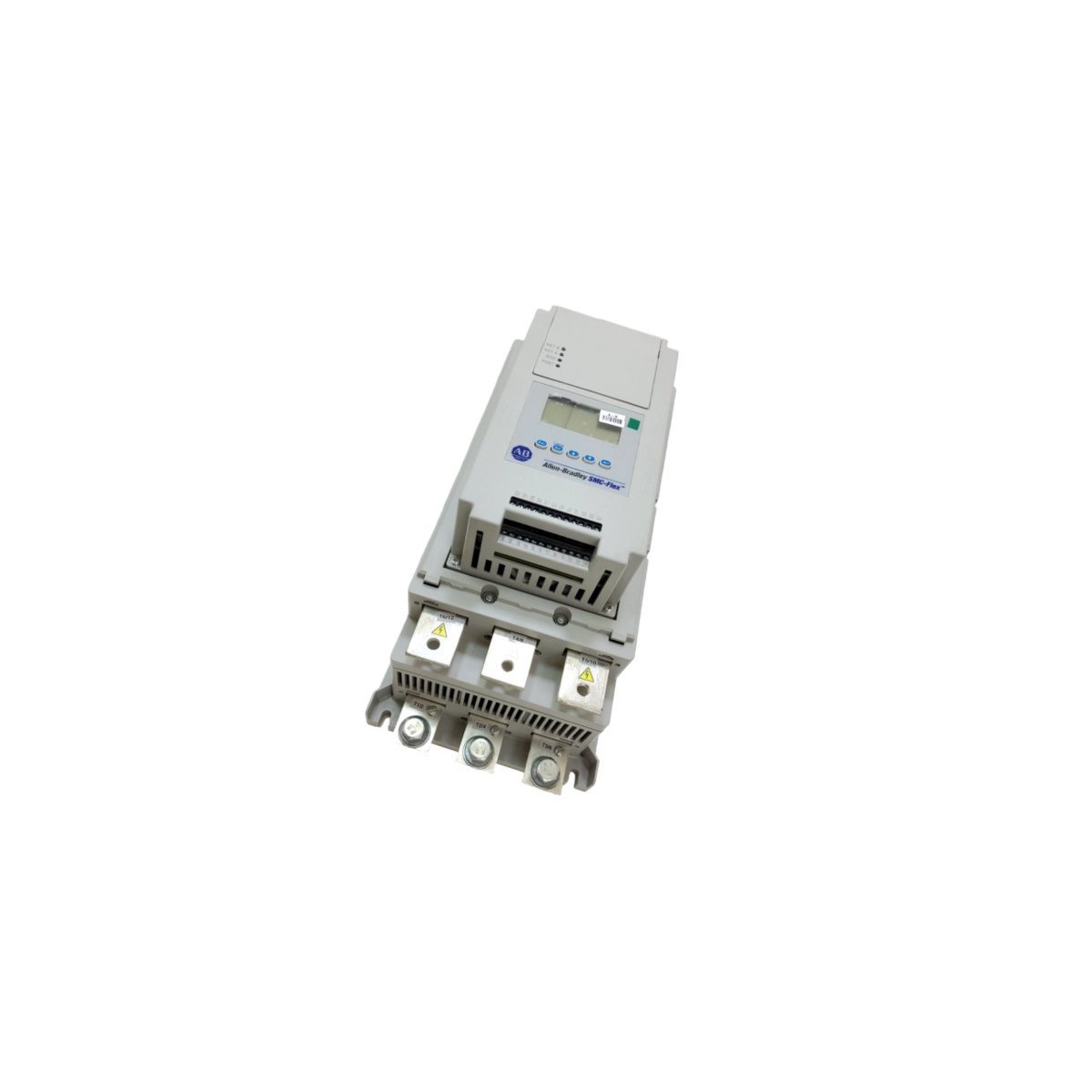
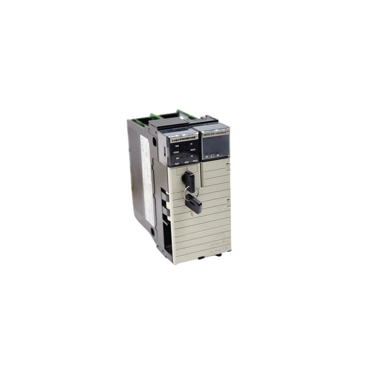
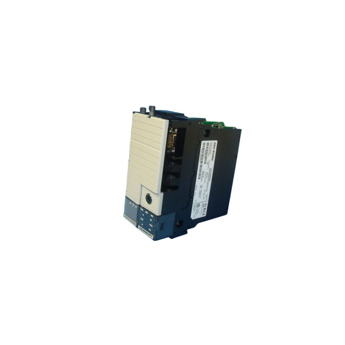
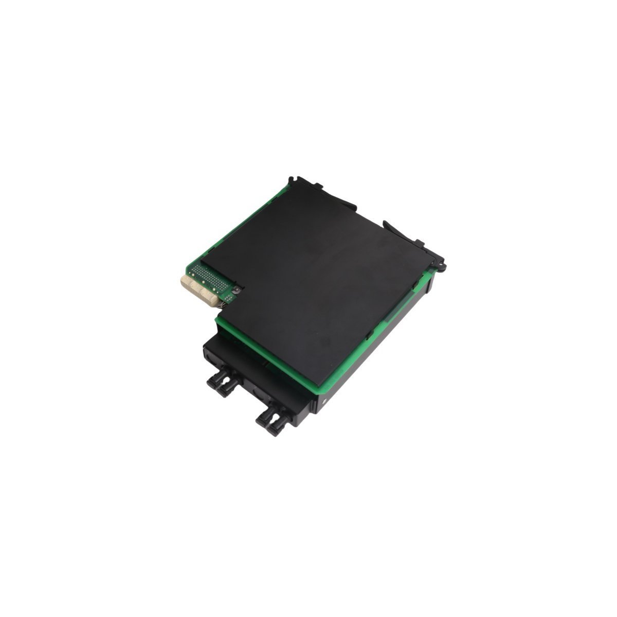
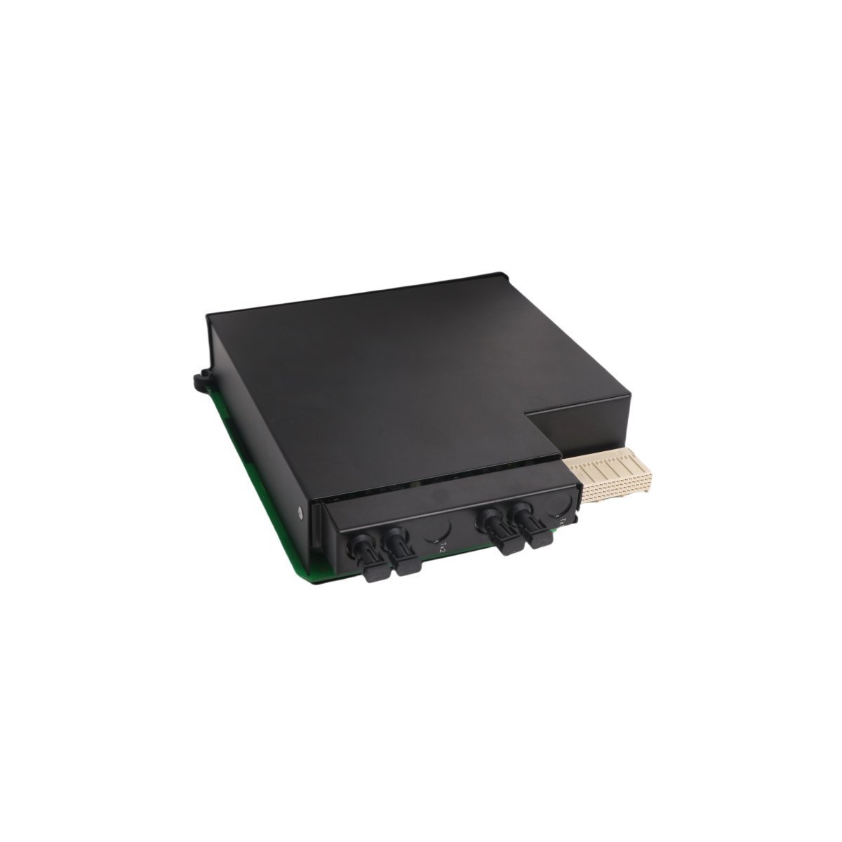
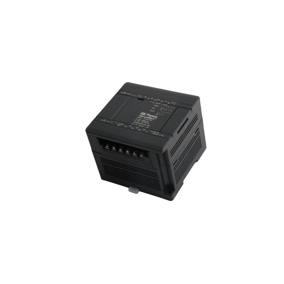
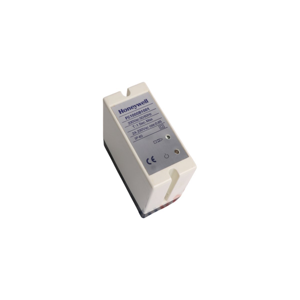
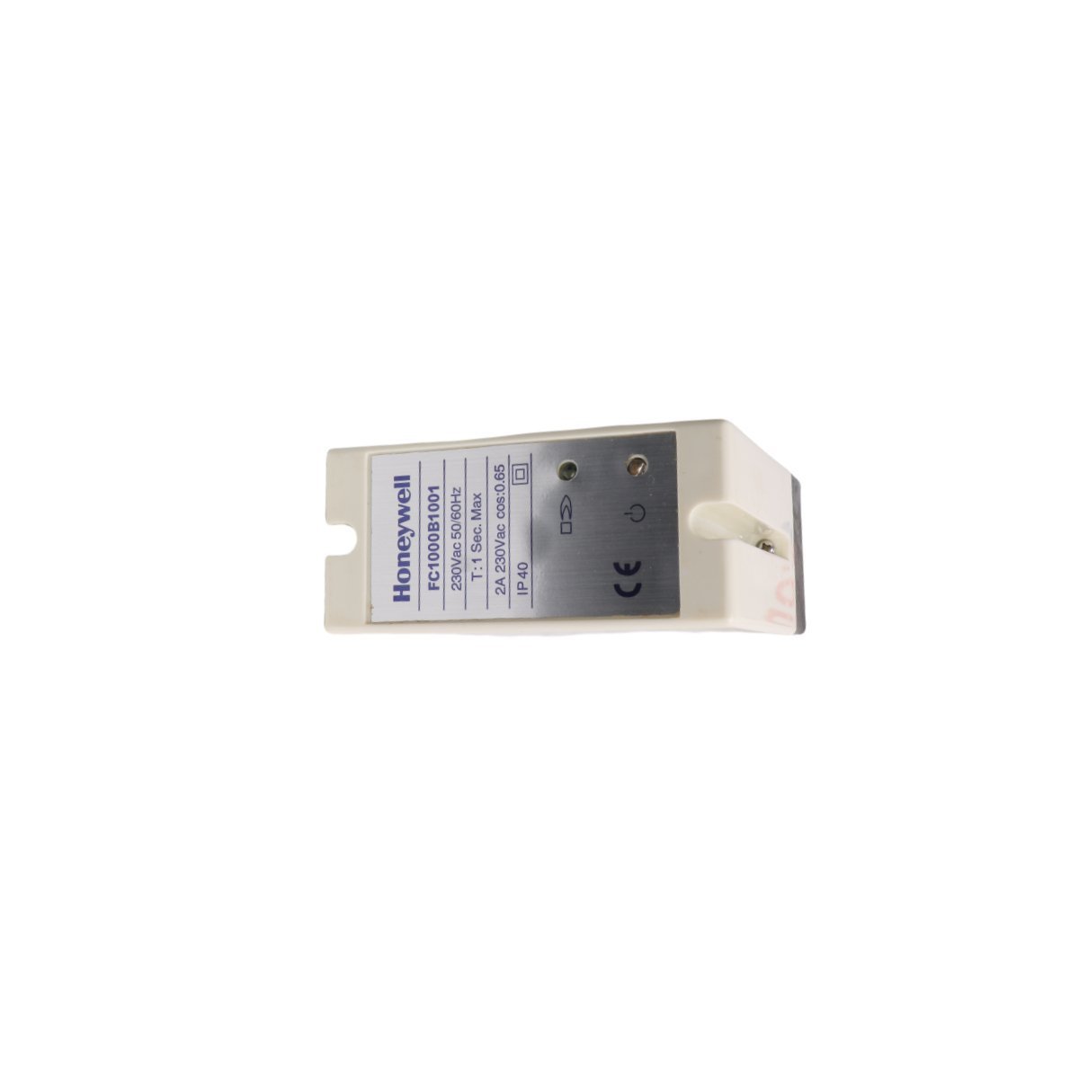
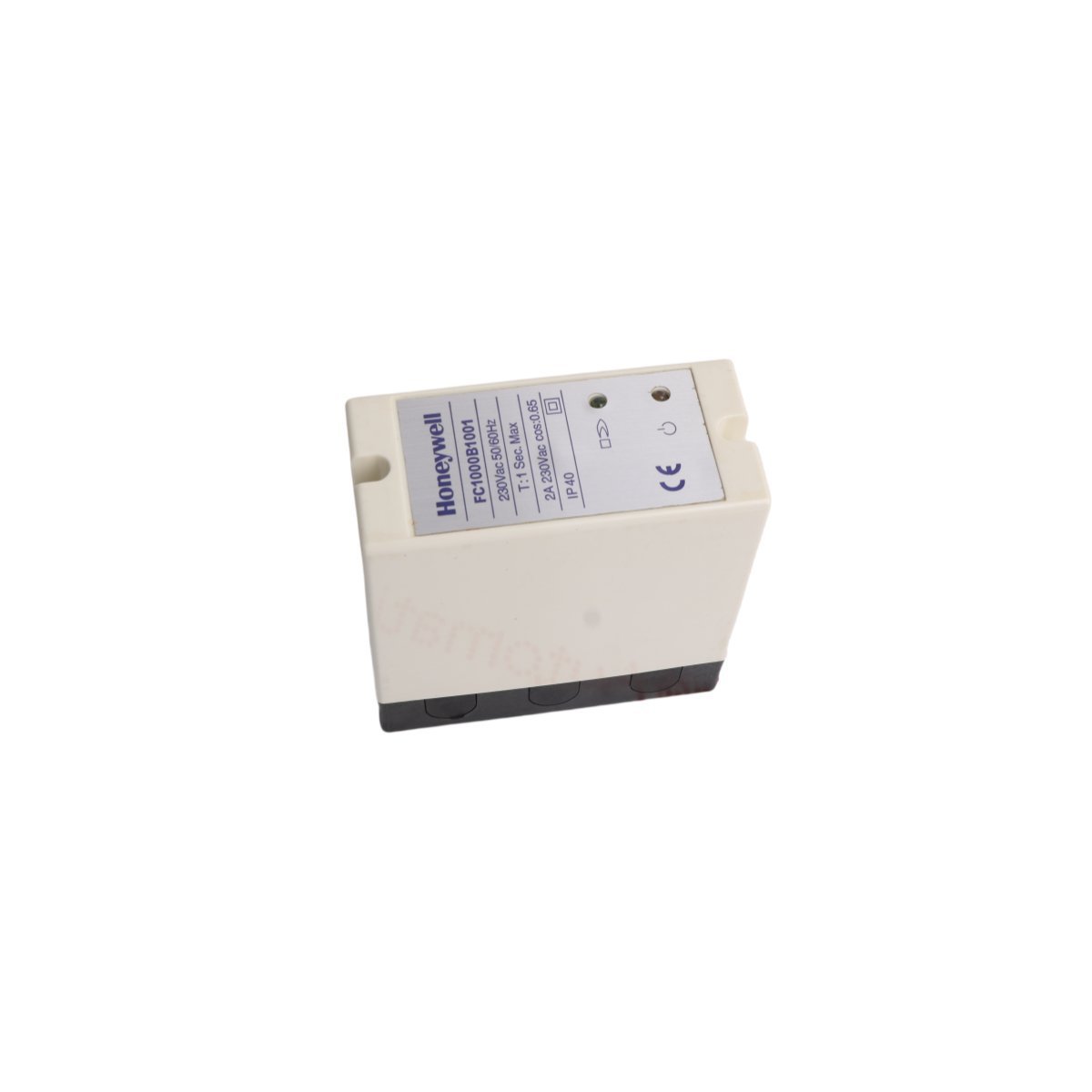
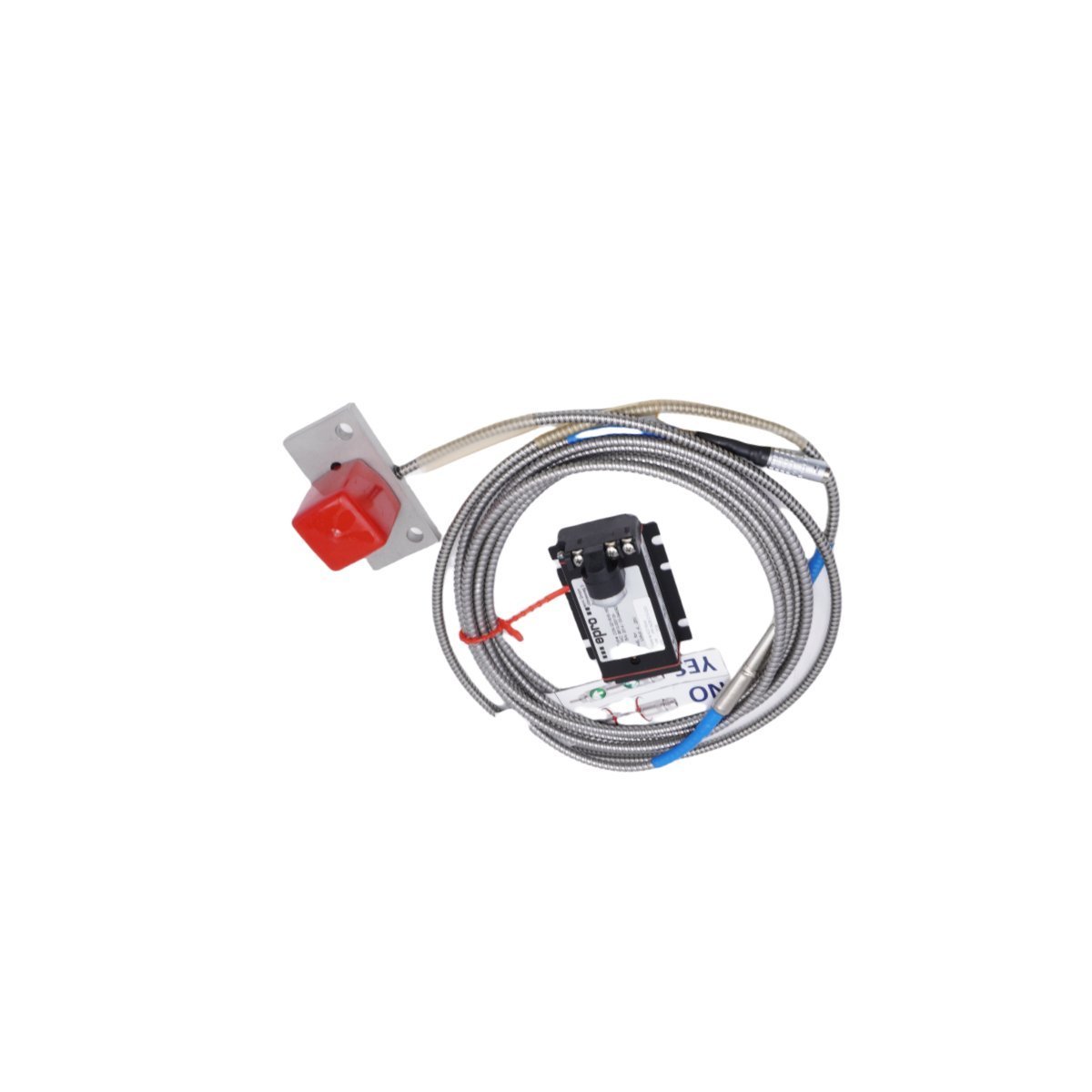
Honeywell FC1000B1001 Flame Combustion Controller

The Honeywell FC1000B1001, also cataloged as the FC1000B1001 Flame Combustion Controller, operates as a dedicated hardware component for flame monitoring and combustion management within DCS platforms.

Hardware Specifications

ParameterSpecification
ModelFC1000B1001
BrandHoneywell
OriginUSA
Weight0.42 kg
Dimensions11.5 cm x 11.0 cm x 5.2 cm
Operating TempConsult system environmental specs
Power ConsumptionDetermined by operational load
SystemDCS

Process Control and DCS Connectivity

This controller manages 4-20 mA HART loop protocol signaling to maintain precise flame combustion parameters. The module provides channel-to-channel isolation to prevent electrical interference between localized burner sensors and the broader DCS communication bus. Internal cold junction compensation (CJC) is integrated to stabilize temperature-dependent sensor inputs during active combustion monitoring.

Frequently Asked Questions

Q: Is this controller compatible with redundant DCS I/O configurations?

A: The FC1000B1001 is designed for integration into standard DCS architectures; ensure the host controller firmware supports the specific flame monitoring logic before commissioning redundant paths.

Q: What are the requirements for physical mounting and heat dissipation?

A: The module must be installed in a standard industrial enclosure with adequate clearance to allow convective airflow. Avoid installing directly above high-heat sources to maintain internal component operating limits.

Q: How is the fieldbus communication path verified during installation?

A: Utilize the DCS engineering workstation to monitor the signal register mapped to the FC1000B1001. Confirm loop continuity and signal health via diagnostic status bits in the controller communication service.

Field Installation Guidelines

  • Ensure the control cabinet is de-energized before inserting or removing the controller from the backplane.
  • Verify that field wiring is terminated according to the provided wiring diagram, ensuring proper shield grounding to the chassis terminal.
  • Confirm all terminal screws are tightened to the specified torque to prevent intermittent contact resistance during operation.
  • Perform a point-to-point loop check after installation to verify sensor feedback is correctly translated within the DCS environment.