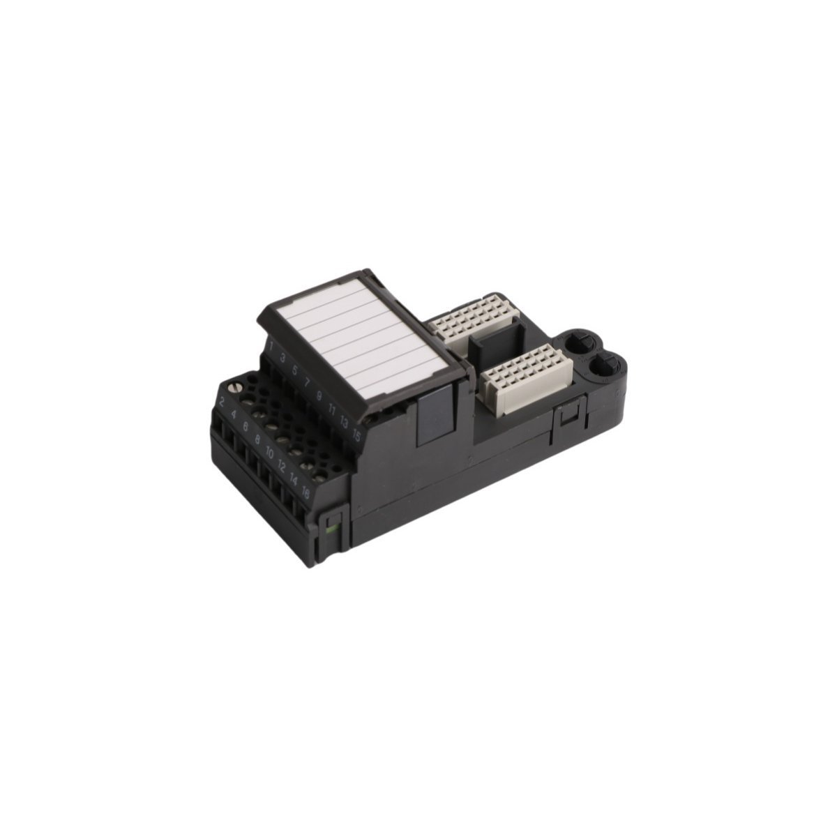
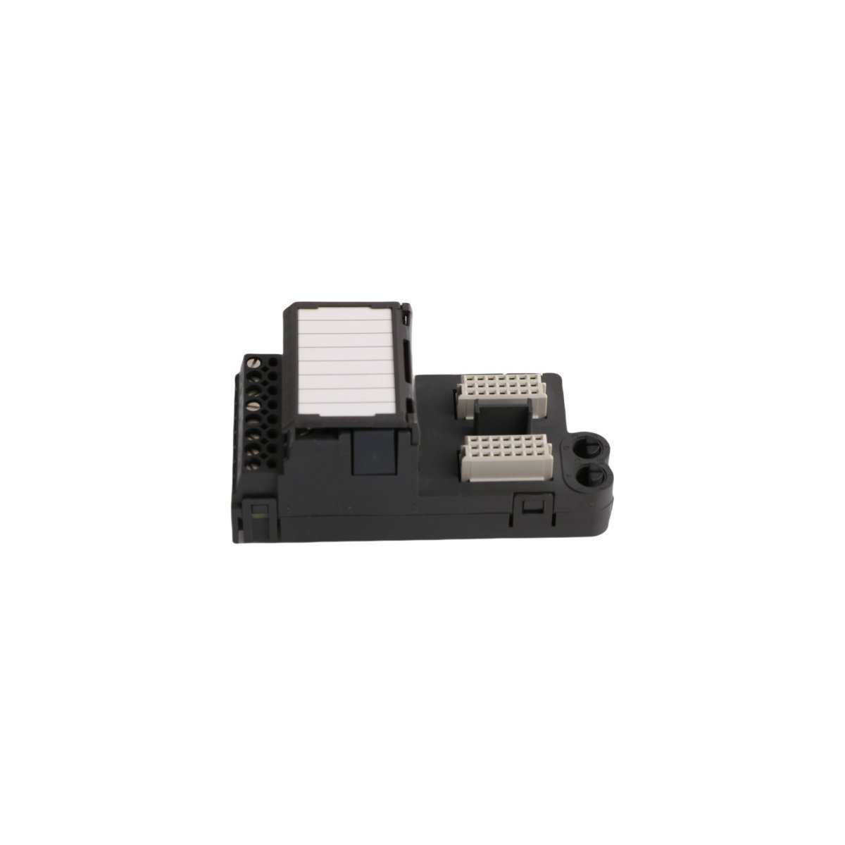
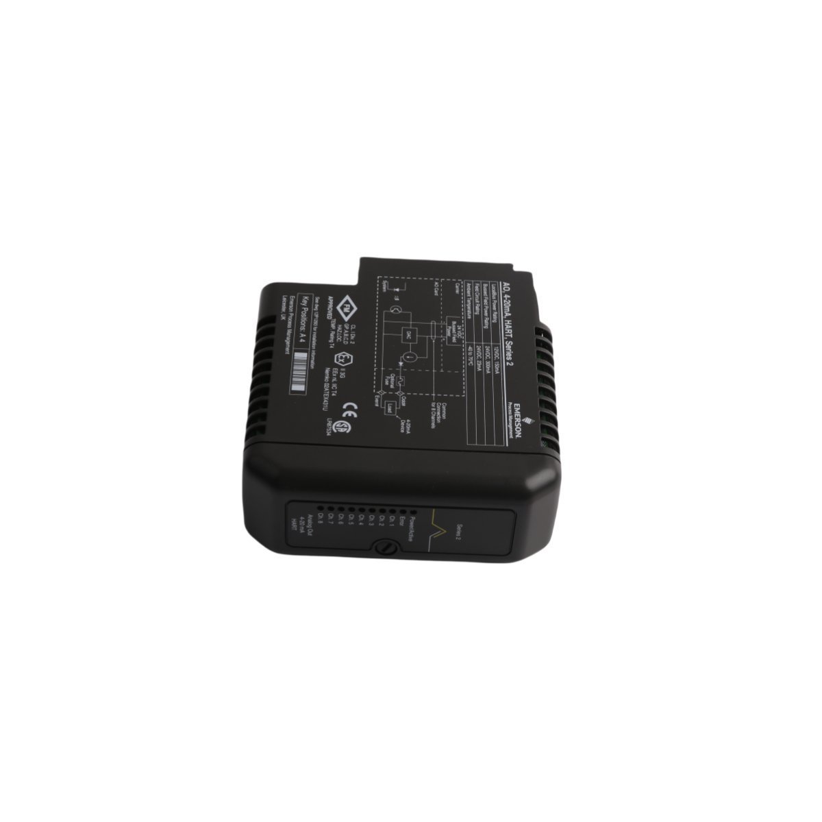
The Honeywell 51204146-050 is an industrial micro logic controller for the Experion PKS platform. Features a 20 MHz engine, 16 integrated I/O channels, and Modbus/CANopen communication interfaces. Genuine original, brand-new stock is ready for immediate worldwide dispatch. Enhance your skid automation stability today.
The Honeywell 51204146-050 is a compact, high-reliability Micro Logic Controller Module designed for the Experion® Process Knowledge System (PKS) architecture, specifically serving as a processing component within the C200/C200E controller series. Engineered to balance cost-effectiveness with industrial-grade control depth, this micro-controller manages small-to-medium process loops, standalone skid logic, and localized equipment sequencing tasks.
Hardware Specifications
Parameter
Specification
Model / Catalog No.
51204146-050
Manufacturer
HONEYWELL (Experion PKS C200/C200E Series)
Origin
USA
Weight
0.4 kg
Dimensions
7.0 x 14.0 x 14.5 cm
Module Type
Micro Logic Controller Processor
Processor Speed
20 MHz
Memory Architecture
64 KB RAM / 128 KB Flash Memory
Onboard I/O Capacity
16 Configurable I/O Channels
Input Operating Voltage
12–24 VDC
Operating Temperature Range
-20°C to +60°C
System Lifecycle
Active
Controller Architecture & Embedded I/O Engine
The 51204146-050 combines a dedicated 20 MHz execution processor with built-in memory registers to deliver deterministic scan times for edge-automation environments. It packs 16 multi-purpose onboard I/O channels directly into its compact frame, minimizing the physical space required for auxiliary connection blocks.
The controller is fully compatible with standard international programming paradigms under the IEC 61131-3 engineering environment. This allows automation developers to deploy control logic using multiple native formats within the same runtime environment:
Ladder Logic (LD): Optimized for discrete sequencing, relay patterns, and interlock grids.
Function Block Diagram (FBD): Designed for continuous process control loops, PID tuning cascades, and math operations.
Structured Text (ST): Ideal for complex data manipulation algorithms, array sorting, and custom communication calculations.
Industrial Networking & Communication Matrix
To guarantee seamless data sharing with supervisory Distributed Control Systems (DCS), Human-Machine Interfaces (HMIs), and third-party smart hardware, the 51204146-050 features dual physical serial and network ports. It serves as a localized field node, routing data packages seamlessly through two main interfaces:
Industrial Ethernet Interface: Natively runs high-speed protocols such as Modbus TCP and Honeywell-specific peer-to-peer control networks.
RS-485 Serial Interface: Configurable to support standard multi-drop infrastructure, allowing direct control over Modbus RTU/ASCII sub-networks or specialized CANopen fieldbus devices.
Frequently Asked Questions
Q: What is the main structural application difference between this module and a standard C300 controller? A: While the C300 platform is designed as a large, vertically oriented processing block for massive plant-wide automation loops, the C200-series 51204146-050 utilizes a compact chassis structure. This makes it ideal for independent manufacturing machinery, water-treatment skid systems, and utility infrastructure management.
Q: How does the Flash memory setup protect the module against unexpected power loss? A: The 51204146-050 stores its compiled execution logic directly within its 128 KB non-volatile Flash Memory. If a complete auxiliary 24 VDC power failure occurs, the operational program remains safe without requiring a backup battery, allowing the controller to immediately resume safe loop execution as soon as power returns.
Field Installation Guidelines
Chassis Alignment: Slide the module firmly into its slot on the backplane rack until the top and bottom extraction levers click. This ensures the 51204146-050 engages correctly with the internal 5V logic power lines and data bus paths.
Shielding Signal Runs: Route all low-voltage RS-485 serial communication runs and analog sensor lines through dedicated, grounded metallic conduit channels. Keep these runs separated from high-current AC motor supply leads to eliminate electromagnetic interference (EMI).
Thermal Management: When installing the module inside an enclosed NEMA junction box, verify that natural convection or exhaust fans maintain internal ambient air temperatures strictly between the safe limits of -20°C and +60°C.
Configured for signal distribution in DeltaV M-series I/O Subsystem networks, the Emerson KJ4001X1-CA1 12P0623X072 (KJ4001X1-CA1 4-Wire Terminal Block) provides direct physical/electrical execution.
The KJ4001X1-CA1 functions as a passive interconnect interface within the DeltaV DCS architecture and facilitates direct field-to-I/O card connectivity. This terminal block secures 4-wire field signal connections and ensures consistent electrical continuity for both analog and discrete signal loops. Field engineers must follow DeltaV backplane wiring standards to maintain signal integrity and prevent impedance mismatches throughout the control loop. The design accommodates high-density terminal mounting and provides a structured physical path for 4-20 mA HART loop protocol signals, which standard process instrumentation requires.
Frequently Asked Questions
Q: Does the KJ4001X1-CA1 terminal block require external power for operation?A: No, this is a passive component. It functions solely as a physical connection interface for field wiring to the I/O subsystem backplane.Q: Is this module compatible with live field-wiring replacement?A: The terminal block supports field-wiring termination maintenance, but users must ensure the associated I/O card is powered down or in a safe state before disconnecting wiring to avoid accidental loops or short circuits.
Field Installation Guidelines
Mount the terminal block securely onto the designated DIN-rail within the DeltaV I/O carrier.
Ensure all terminal screws are tightened to the torque specifications provided in the DeltaV installation manual to prevent high-resistance contact points.
Verify wire gauges comply with terminal specifications to ensure mechanical stability.
Maintain proper wire dressing and cable tie-down spacing to prevent mechanical stress on the terminal connectors.
Ground the cable shields according to standard DCS loop-wiring practices to minimize electromagnetic interference (EMI) ingress into the analog signal path.
Configured for signal termination in DeltaV SIS process safety system networks, the Emerson KJ2201X1-JA1 12P3323X022 (KJ2201X1-JA1 SLS Redundant Terminal Block) provides direct physical/electrical execution.
The KJ2201X1-JA1 functions as a passive interconnect interface within the DeltaV SIS architecture and facilitates direct field-to-I/O card connectivity. This terminal block secures redundant field signal connections and ensures consistent electrical continuity for critical safety loops. Field engineers must follow DeltaV backplane wiring standards to maintain signal integrity and prevent impedance mismatches throughout the safety control loop. The design accommodates high-density terminal mounting and provides a structured physical path for signals requiring 4-20 mA HART loop protocol connectivity, which standard process instrumentation demands.
Frequently Asked Questions
Q: Does the KJ2201X1-JA1 require external power for internal switching?A: No, this unit is a passive termination component. It relies on the connected DeltaV SIS I/O card for logic execution and loop power distribution.Q: How does this terminal block support redundant system configurations?A: The hardware architecture provides dual-path termination points, allowing the SIS controller to monitor and execute fail-safe state transitions across redundant signal channels without hardware reconfiguration.
Field Installation Guidelines
Secure the terminal block onto the specified DIN-rail mounting position within the DeltaV SIS carrier.
Tighten all terminal screws to the manufacturer-specified torque limits to prevent intermittent contact resistance under vibration.
Terminate field wiring according to the loop diagram to ensure correct channel mapping.
Route shielded cables through designated cable trays to minimize electromagnetic interference (EMI) impact on analog signal precision.
Verify electrical continuity across the redundant paths using a calibrated multimeter before energizing the I/O loop.
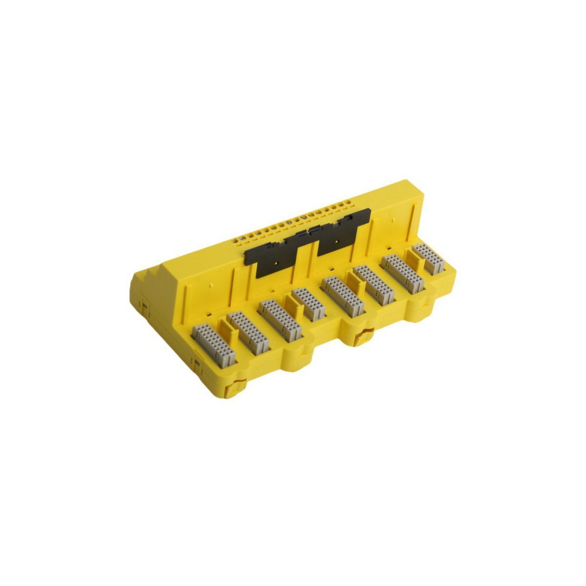
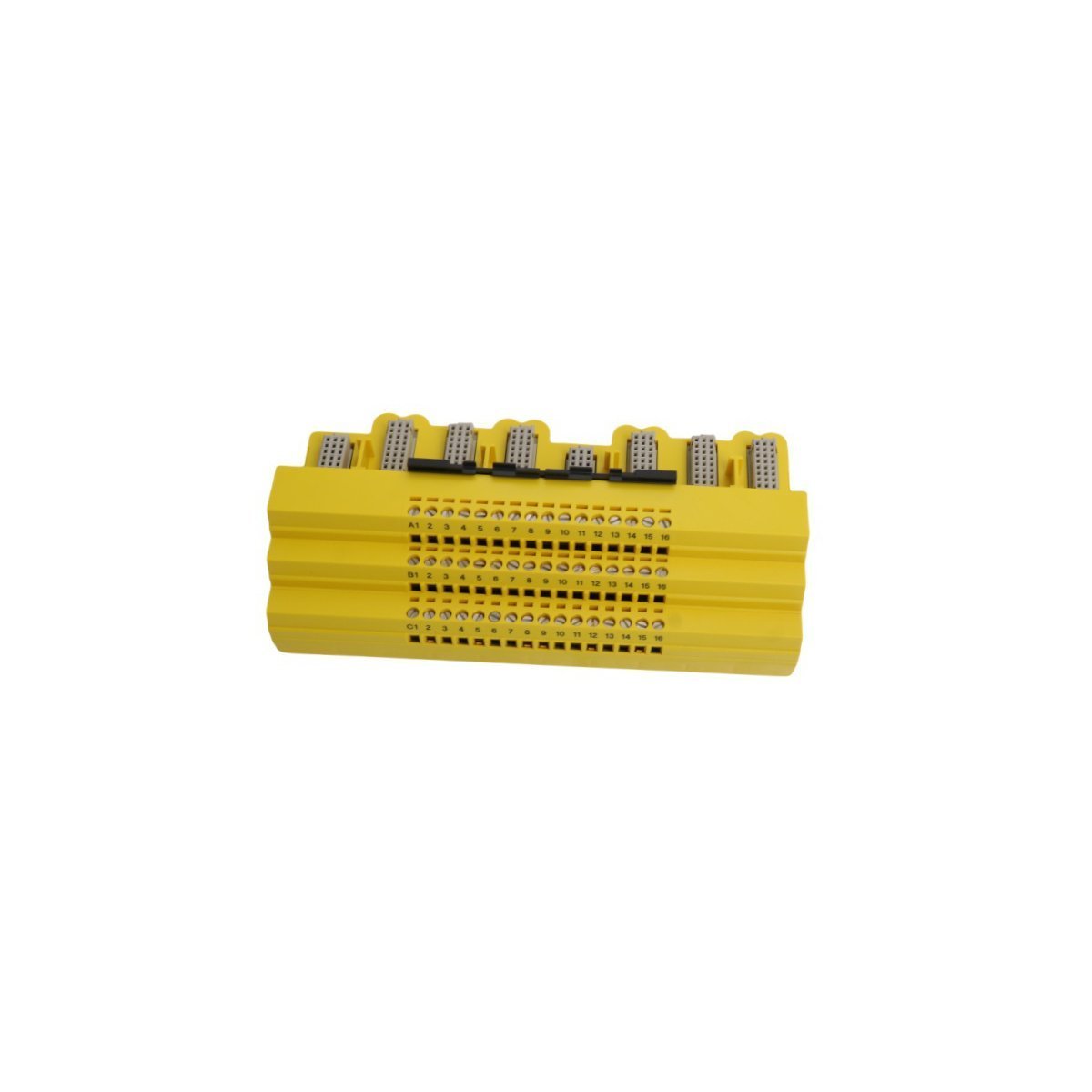
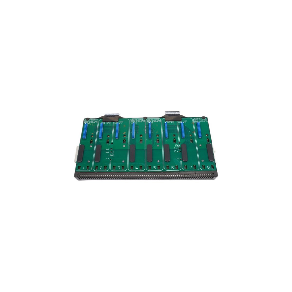
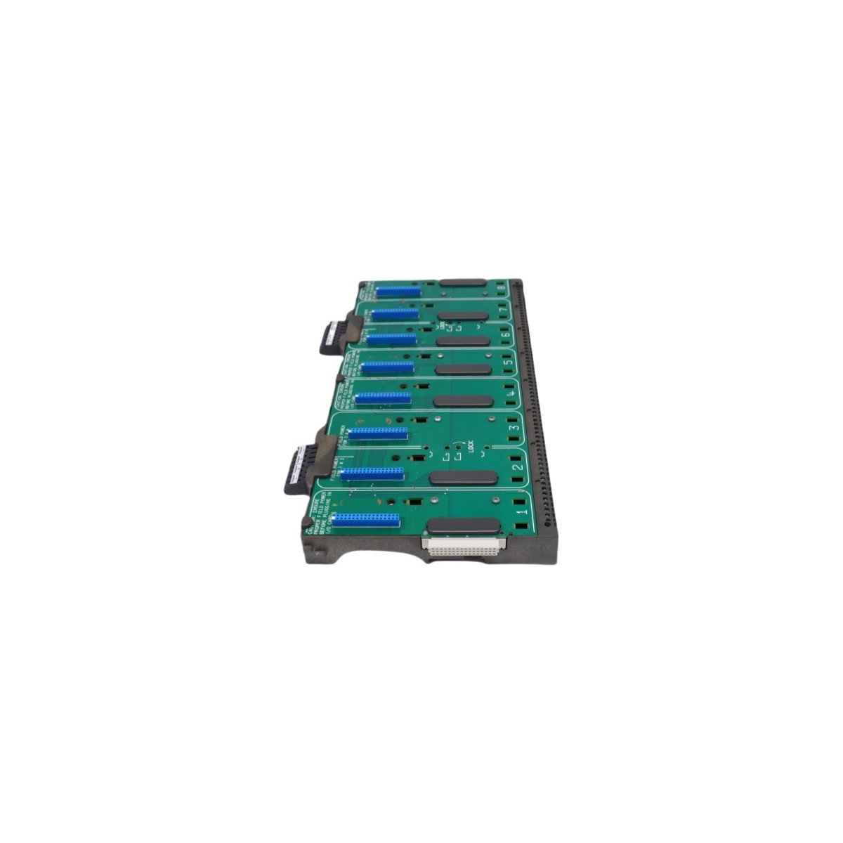
Configured for high-density signal distribution in DeltaV M-series I/O Subsystem networks, the Emerson KJ4001X1-BE1 12P0818X072 (KJ4001X1-BE1 8-Wide IO Carrier) provides direct physical/electrical execution.
Suffix Breakdown & Model Matrix
Model
Description
KJ4001X1-BE1
DeltaV M-series 8-wide I/O carrier with integrated shielding
The KJ4001X1-BE1 acts as the physical backbone for M-series I/O card mounting and signal termination. This carrier features a shielded design to isolate backplane communications from external electromagnetic interference (EMI). It supports 8-wide module placement, facilitating high-density I/O configurations while maintaining strict electrical separation between signal loops. The carrier integrates with the DeltaV system bus to manage data throughput and power distribution across all installed I/O modules. Users must adhere to proper shielding ground practices to ensure the 4-20 mA HART loop protocol signals maintain their rated accuracy during transmission.
Frequently Asked Questions
Q: Does the carrier support hot-swapping of I/O modules?A: Yes, the DeltaV M-series backplane architecture supports the removal and insertion of I/O modules while the carrier is energized, provided the specific I/O module type allows for such operations under the defined safety and process conditions.Q: How does the integrated shielding function?A: The carrier incorporates a conductive chassis plane that connects to the system earth ground. This plane acts as an EMI shield for the underlying bus communication traces, preventing noise coupling into sensitive analog input circuits.
Field Installation Guidelines
Mount the carrier horizontally on a standard DIN-rail or chassis plate within the control cabinet.
Verify that the carrier backplane ground lug connects securely to a low-impedance earth ground to satisfy EMI protection requirements.
Ensure all I/O modules seat firmly into the connector slots to prevent backplane bus communication timeouts or intermittent signal loss.
Maintain adequate clearance above and below the carrier to facilitate heat dissipation and cabling access.
Inspect all terminal blocks for loose connections after installation to ensure low-resistance contact for all signal and power circuits.
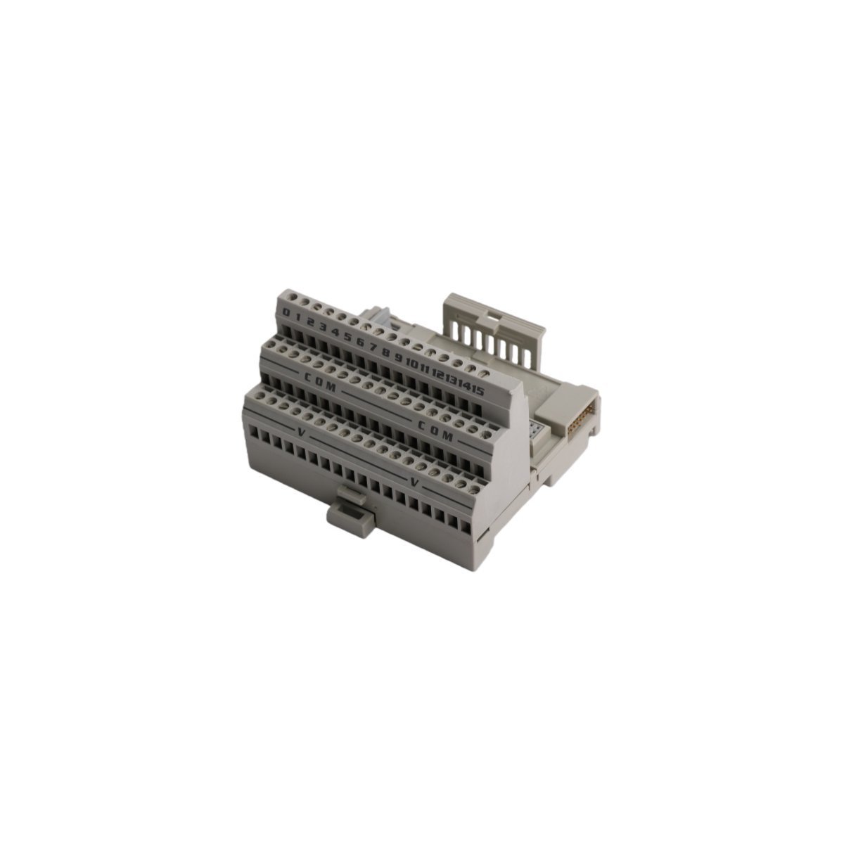
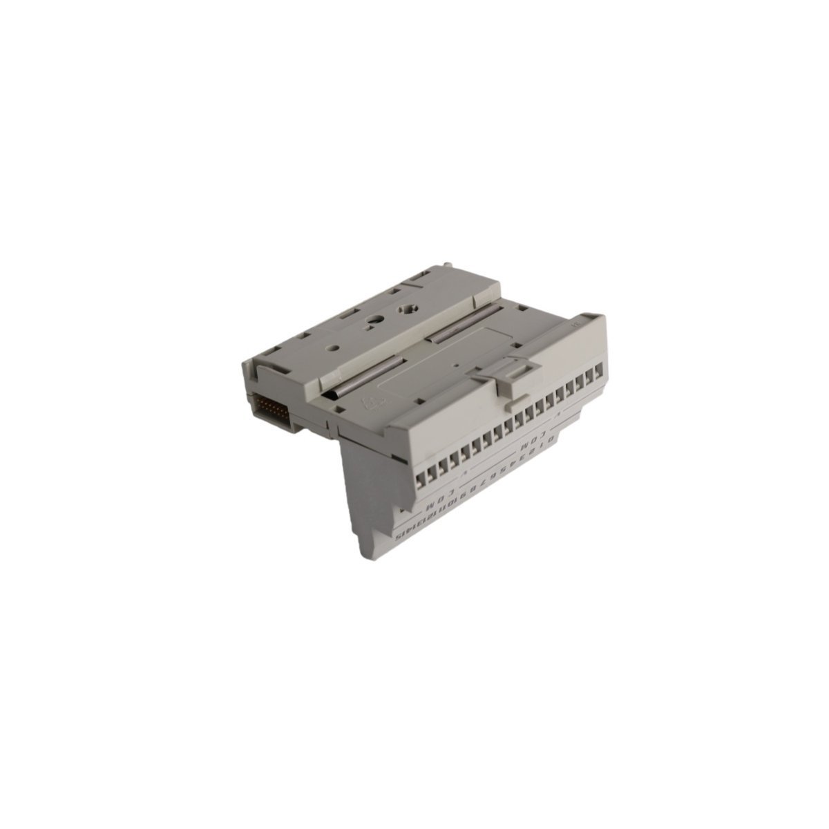
The Allen-Bradley 1794-TB3K, also cataloged as the 1794-TB3K Base Unit, operates as a dedicated hardware component for field device termination and modular I/O mounting within FLEX I/O control networks.
Hardware Specifications
Parameter
Specification
Model
1794-TB3K
Brand
Allen-Bradley
Origin
USA
Weight
0.9 kg
Dimensions
3.5 cm x 13 cm x 14.5 cm
Operating Temp
-20 deg C to 70 deg C
Power Consumption
Not specified
Current Rating
10 A at 125 V AC/DC
Industrial Control System Connectivity
The 1794-TB3K integrates into industrial control architectures by utilizing backplane bus communication velocity protocols for real-time data exchange. This terminal base architecture facilitates I/O density scaling within the control cabinet, which allows engineers to coordinate power distribution across multiple feedback loops. Furthermore, the module supports firmware flash compatibility via the associated I/O adapter, ensuring that system logic aligns with operational requirements. Consequently, the hardware ensures deterministic signal transmission during power threshold excursions.
Frequently Asked Questions (FAQ)
Q: Does the 1794-TB3K support hot-swapping of I/O modules?A: Yes, the 1794-TB3K terminal base supports the removal and insertion of compatible FLEX I/O modules while the system is powered, provided that the associated module design permits such operations.Q: What is the maximum wire gauge supported by the screw-clamp terminals?A: The terminal blocks accommodate stranded copper wires ranging from 24 AWG to 16 AWG; for optimal mechanical and electrical contact, maintain a torque setting between 0.56 Nm and 0.79 Nm.
Field Installation Guidelines
To begin with, verify that the DIN rail is securely mounted and properly grounded before you position the terminal base; subsequently, hook the unit onto the rail and press firmly until the locking mechanism engages.
Furthermore, ensure all power to the I/O bus is isolated before you land any field wiring to the terminal blocks; meanwhile, strip the insulation according to manufacturer specifications to prevent exposed copper.
In addition, torque each screw-clamp to the specified 0.56-0.79 Nm range to ensure a vibration-resistant connection; then, verify that no conductor strands are pinched between the terminal and the housing.
Following wiring, perform a point-to-point continuity check to confirm that signal paths align with your schematic; by doing so, you mitigate the risk of short-circuits during system power-up.
Finally, snap the compatible I/O module onto the base until it clicks into place; thereby, you establish a secure electrical interface for the FLEX I/O network.
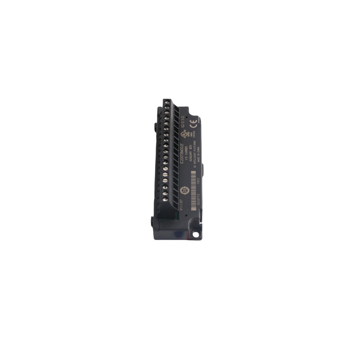
The GE IC200TBM002, also cataloged as the IC200TBM002 I/O terminal block, operates as a dedicated hardware component for signal distribution and wiring termination within VersaMax PLC systems. Configured for high-density I/O routing, the block provides direct physical execution of signal bussing through 18 integrated IEC-compliant box-style terminals. This module facilitates electrical interfacing for input/output carriers and interposing terminals, ensuring standardized connectivity for industrial field wiring.
Hardware Specifications
Parameter
Specification
Model
IC200TBM002
Brand
GE
Origin
USA
Weight
0.06 kg
Dimensions
11.0 cm x 3.5 cm x 3.0 cm
Operating Temp
Standard Industrial Range
Power Consumption
Passive (No active components)
Voltage Rating
264 VAC (Up to 300 VAC tolerance)
Current Rating
8 A
PLC and Control Network Integration
The VersaMax series utilizes modular backplane bus communication velocity and deterministic synchronization to manage distributed I/O blocks. Moreover, firmware flash compatibility within the host CPU allows for systematic updates across the network, thereby ensuring that hardware configurations remain consistent with logic execution cycles. In addition, I/O density scaling is supported through the flexible mounting interface, which enables the system to expand without exceeding the timing constraints of the host bus. Finally, Profinet and EtherNet/IP deterministic network integration requirements are managed upstream via communication modules, while the IC200TBM002 serves as the physical termination point for local field signals.
Frequently Asked Questions
Q: Does the IC200TBM002 provide electrical isolation between terminals?A: The IC200TBM002 features 18 internally-bussed terminals. It is electrically isolated from the I/O carrier interface; however, within the block itself, the terminals are bussed together to provide a common electrical potential.Q: What is the maximum wire gauge supported by the terminal block?A: The terminal block accommodates solid or stranded wires ranging from AWG #22 to AWG #14. It also supports the connection of two wires per terminal, provided the combined gauge does not exceed AWG #18.
Field Installation Guidelines
The module should be installed using the integrated mounting tabs on the top edge or secured via panel-mounting holes to ensure mechanical stability in high-vibration environments.
Ensure all field wiring is stripped to the appropriate length according to IEC standards before insertion into the box-style terminals to prevent short circuits.
When utilizing the terminal block for power distribution, ensure that the cumulative current across the 18-point bus does not exceed the 8 Amp rating.
Verify proper seating within the insert-slots of the I/O carrier to ensure the mechanical and electrical integrity of the VersaMax I/O assembly.
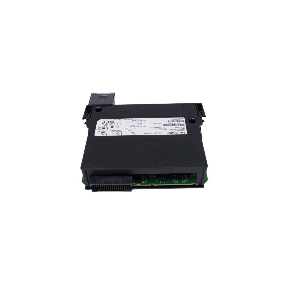
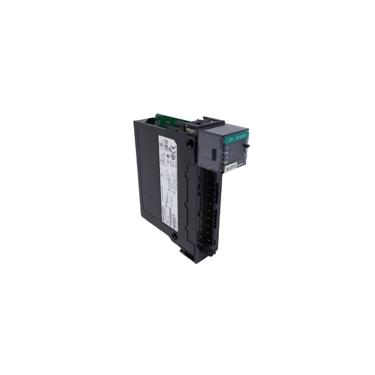
Get the genuine Allen-Bradley 1756-OB16E ControlLogix Discrete Output Module featuring 16 electronically fused points and 24 VDC sourcing outputs. Discontinued Spare, Original Surplus with Global Shipping. Minimize automation downtime now.
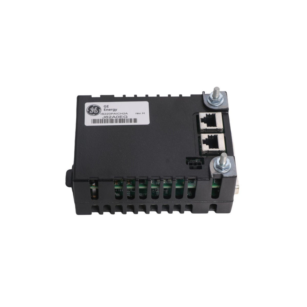
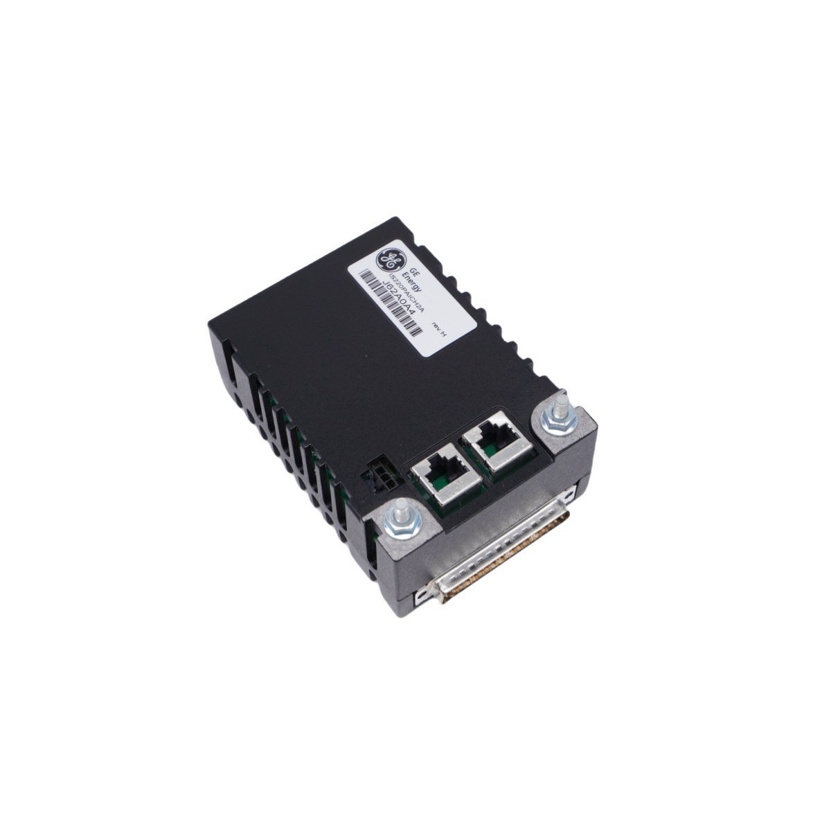
The GE IS220PAICH2A is a high-performance analog I/O pack for Mark VIe turbine control systems. It features 10 configurable analog inputs and 2 current loop outputs, supporting both simplex and TMR configurations for critical process control and monitoring.
The GE IS200SCSAS1AEB is a Simplex Serial Communication (SSCA) I/O board for Mark VIe systems. It supports six channels of RS-232, RS-485, and RS-422 communication, featuring an on-board ID chip for automated diagnostics and flexible DIN-rail or cabinet mounting options.
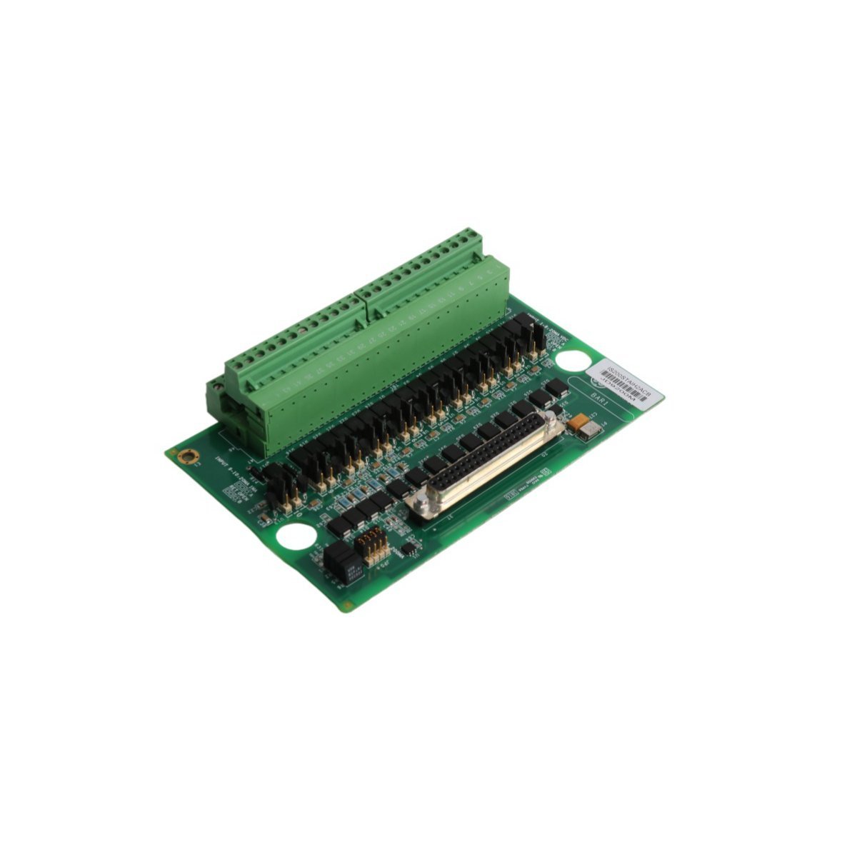
The GE IS200TBAIS1C is a versatile Analog I/O Terminal Board for the Mark VIe series, supporting both Simplex and TMR configurations. It features three DC-37 pin connectors, an integrated ID chip for automated diagnostics, and high-precision current monitoring, making it an essential component for reliable turbine control and signal processing.
The Emerson KJ4001X1-BE1 (12P0818X072) provides a robust 8-wide I/O carrier solution for the DeltaV M-series subsystem. It features high-density module mounting, integrated power distribution, and reliable signal routing for advanced DCS industrial automation environments.
The Emerson KJ3221X1-BA1 (12P2531X062) is a high-reliability DeltaV Redundant I/O Baseplate designed for Series 2 systems. It enables seamless module redundancy and hot-swappable maintenance for critical DCS applications in harsh industrial environments.
The GE Multilin UR6TH is a high-density 16-input and 8-output module for the Universal Relay (UR) platform. Designed for substation-grade protection and control, it offers reliable discrete signal interfacing for GE Multilin G60, L90, and other UR-series units.
We are committed to protecting your privacy. The information collected here is strictly used to provide the requested quotes, technical support, and relevant industrial automation solutions.