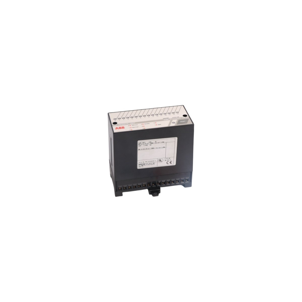
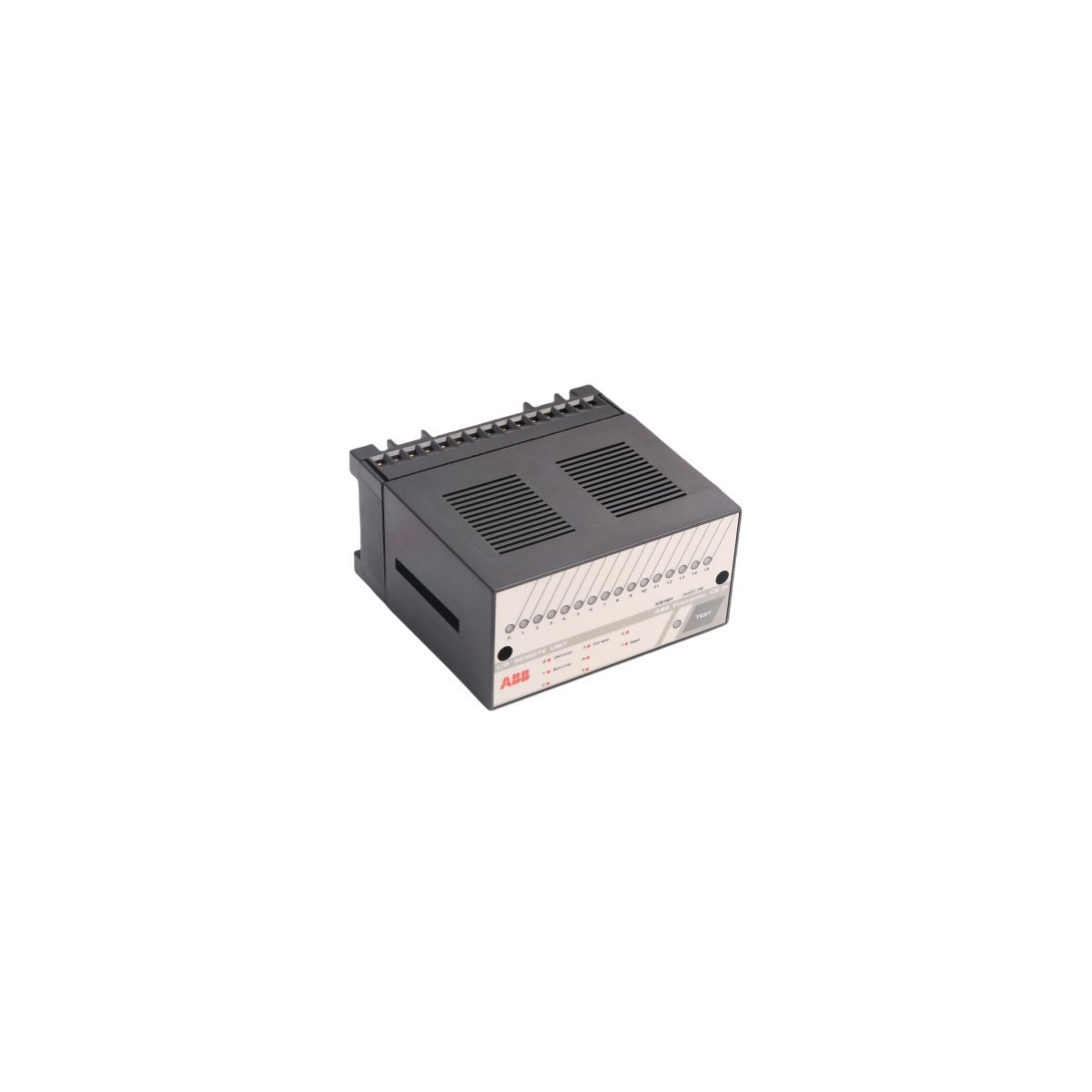
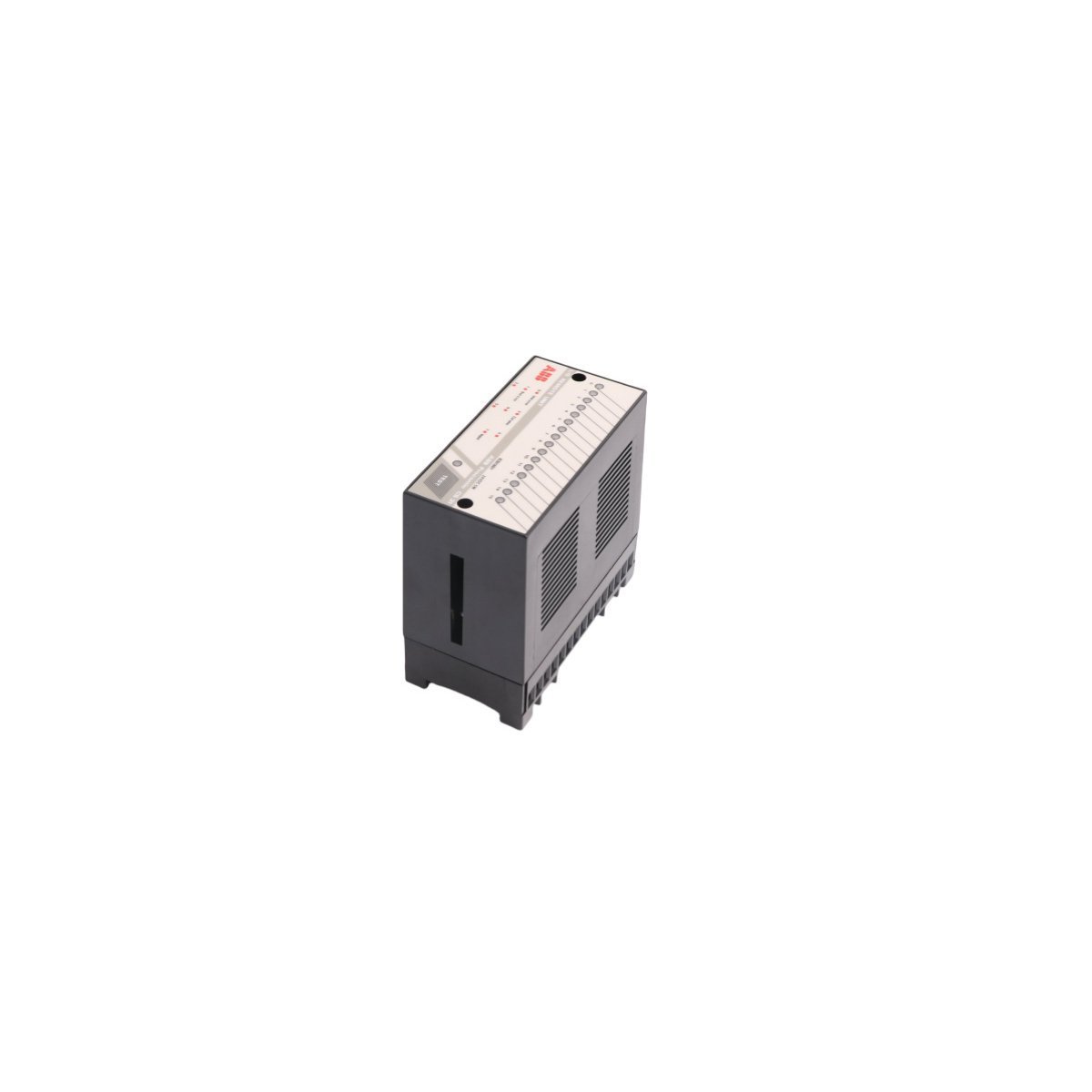
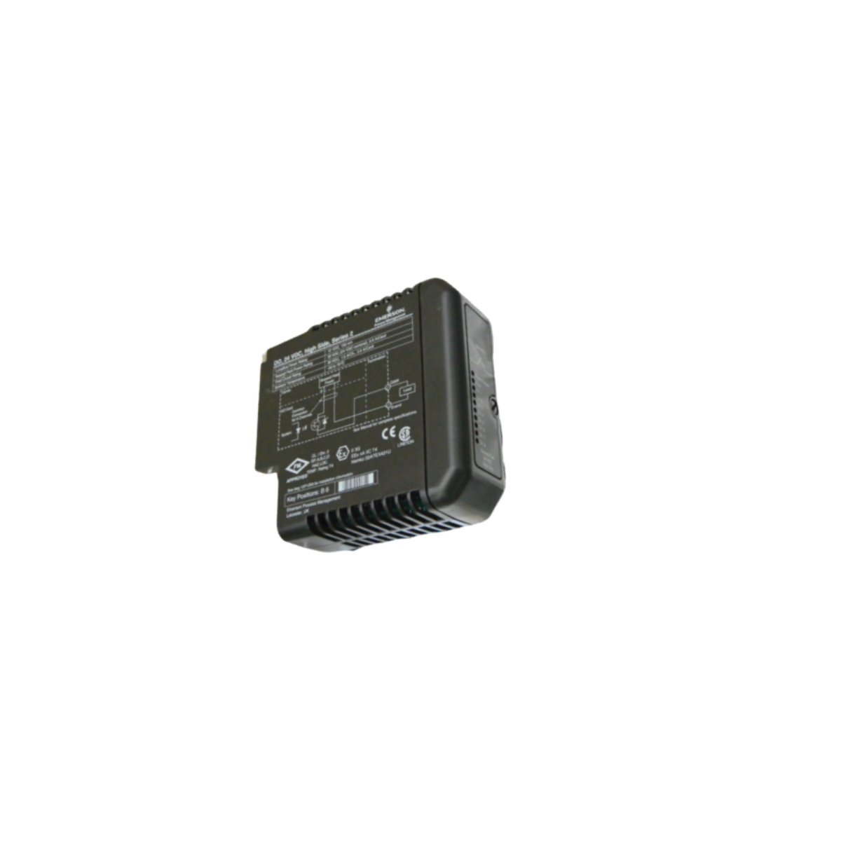
The ABB ICSI16D1, also cataloged as the ICSI16D1 Binary Input Unit, operates as a dedicated hardware component for binary signal acquisition and processing within Procontic CS31 DCS platforms.
Hardware Specifications
Parameter
Specification
Model
ICSI16D1
Brand
ABB
Origin
SWEDEN
Weight
0.44 kg
Dimensions
12.4 x 7.5 x 11.5 cm
Operating Temp
Standard Industrial Grade
Power Consumption
Not specified
Product Range
Procontic CS31
Communication
Ethernet router interface
Deterministic Network Connectivity and Firmware
The integration of this module into the Procontic CS31 environment relies on specific backplane bus communication protocols to ensure deterministic data exchange.Furthermore, users must verify firmware flash compatibility before initial deployment to ensure synchronization with the central controller’s scanning cycle. Consequently, the module manages I/O data throughput by maintaining high-speed signal polling, which is subsequently critical for maintaining scan time integrity across the distributed control network. In addition, strict adherence to these firmware requirements is necessary to prevent communication bottlenecks, thereby preserving the overall deterministic nature of the I/O processing loop.
Frequently Asked Questions (FAQ)
Q: Can the ICSI16D1 module be removed or replaced while the power is active?
A: No, this module does not support hot-swapping. The system power must be isolated and the backplane de-energized before physical removal to prevent damage to the backplane connectors and internal logic circuitry.
Q: How should the module be configured if communication latencies occur?
A: Verify that the Ethernet router settings and bus timing parameters are matched to the Procontic CS31 scan rates. Ensure all termination resistors on the communication bus are correctly installed to prevent signal reflection.
Field Installation Guidelines
Mounting Stability: The module must be installed on a standardized DIN-rail. Ensure the locking latch is fully engaged to maintain structural stability under high-vibration industrial conditions.
Signal Grounding: All binary input signal shields must be terminated at the designated common ground bar to mitigate electromagnetic interference and potential ground loops.
Wiring Precautions: Maintain separation between signal input lines and high-voltage power cables to avoid inductive coupling. Use ferrule-terminated wiring to ensure solid contact within the screw terminals.
Environmental Constraints: Ensure that the mounting cabinet provides adequate convection cooling to maintain operating temperatures within the rated design limits.
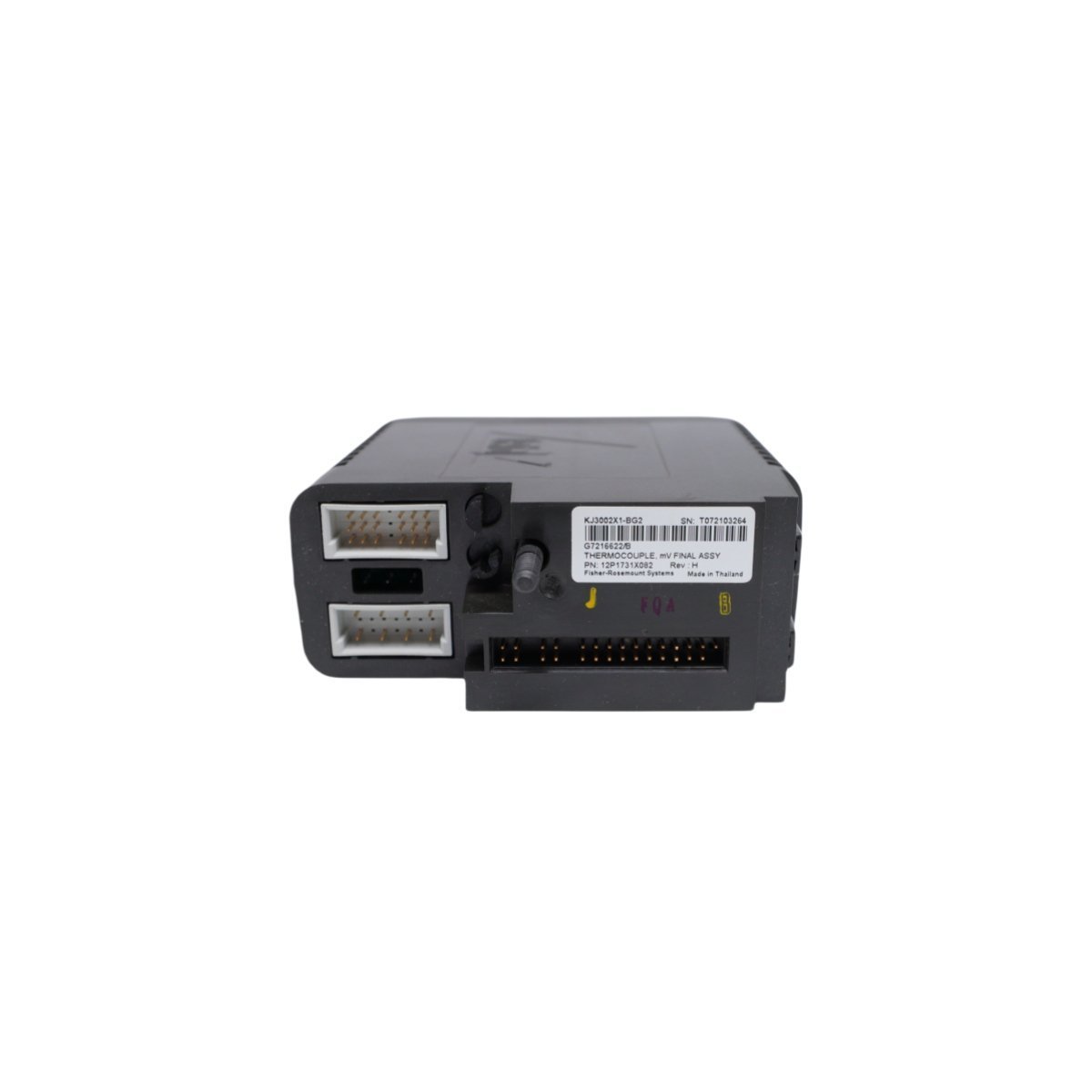
Configured for direct analog signal acquisition in Emerson DeltaV DCS environments, the Emerson KJ3002X1-BG2, also cataloged as the KJ3002X1-BG2 Thermocouple Module, provides direct physical/electrical execution.
Hardware Specifications
Parameter
Specification
Model
KJ3002X1-BG2
Brand
Emerson
Part Number
12P1731X022
System Reference
VE4003S5B1
Range of Product
DeltaV M-series I/O Subsystem
Module Type
Thermocouple Module
Channels
8 Channels
Origin
USA
Weight
0.2 kg
Dimensions
8.1 x 7.9 x 8.8 cm
HS Code
8537101190
Status
Discontinued (Dec 31, 2018)
Process Control and DCS Characteristics
Converts millivolt inputs from field thermocouples into digitized temperature values for system controller processing.
Features integrated cold junction compensation (CJC) algorithms to maintain signal accuracy across varying cabinet temperatures.
Utilizes channel-to-channel isolation architecture to eliminate ground loops and reject common-mode voltage spikes across industrial field cabling.
Incorporates 4-20 mA HART loop protocol carrier compatibility across system backplane interfaces for extended instrument diagnostic passthrough.
Frequently Asked Questions
Q: How does the KJ3002X1-BG2 module perform cold junction compensation?A: Cold junction compensation is maintained via internal thermal sensors embedded on the terminal block assembly, correcting for ambient variations at the wiring termination point.Q: Can the module be inserted or removed while the terminal base is powered?A: Yes, DeltaV M-series I/O modules support power-on insertion and removal (removal under power) when installed on compatible I/O carrier bases.
Field Installation Guidelines
Secure the module onto the DeltaV M-series I/O carrier until the locking mechanisms fully engage with the backplane base.
Ensure shielded thermocouple wiring is grounded at a single point to prevent high-frequency noise interference on low-millivolt input channels.
Maintain a minimum bending clearance for field wiring to prevent mechanical stress on terminal connectors.
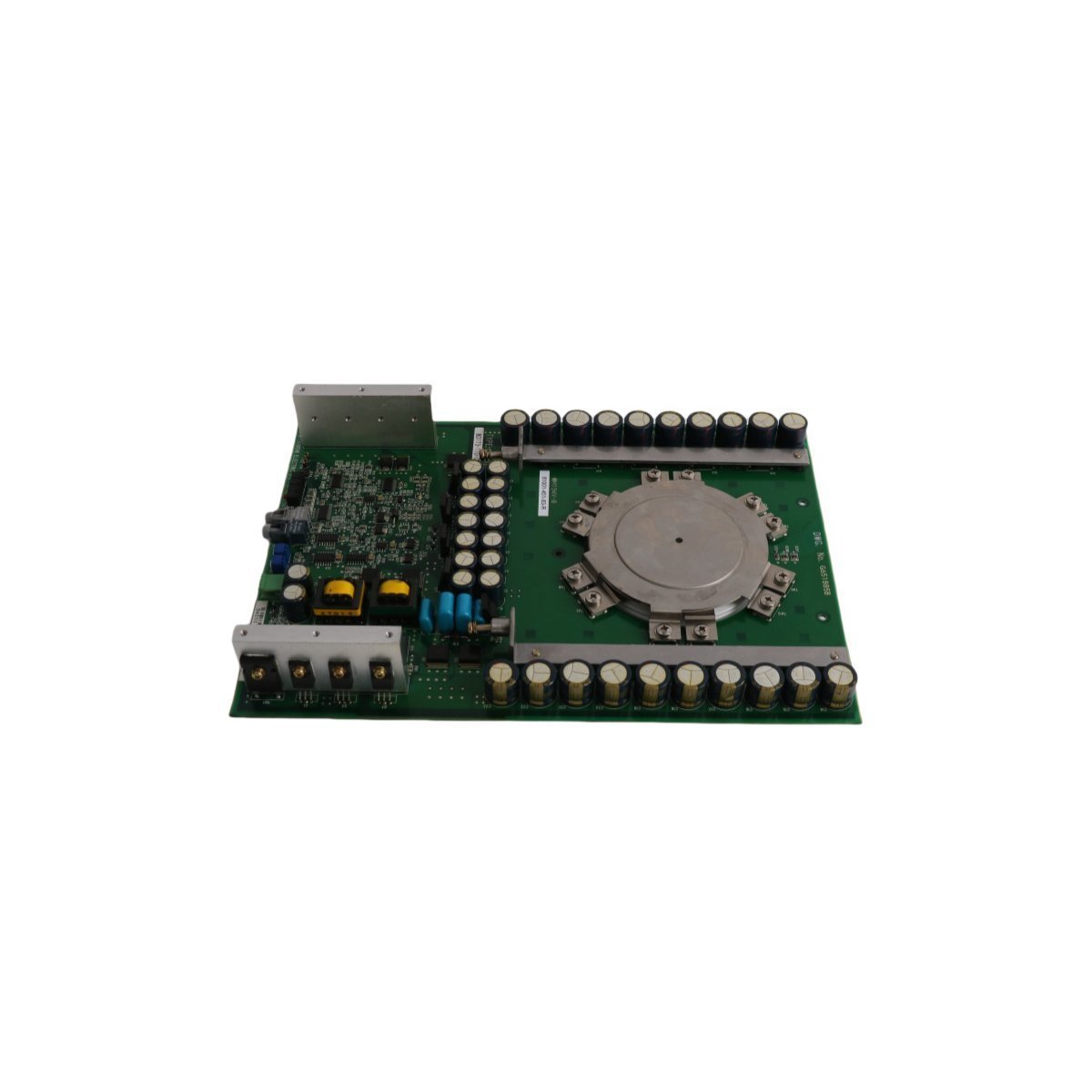
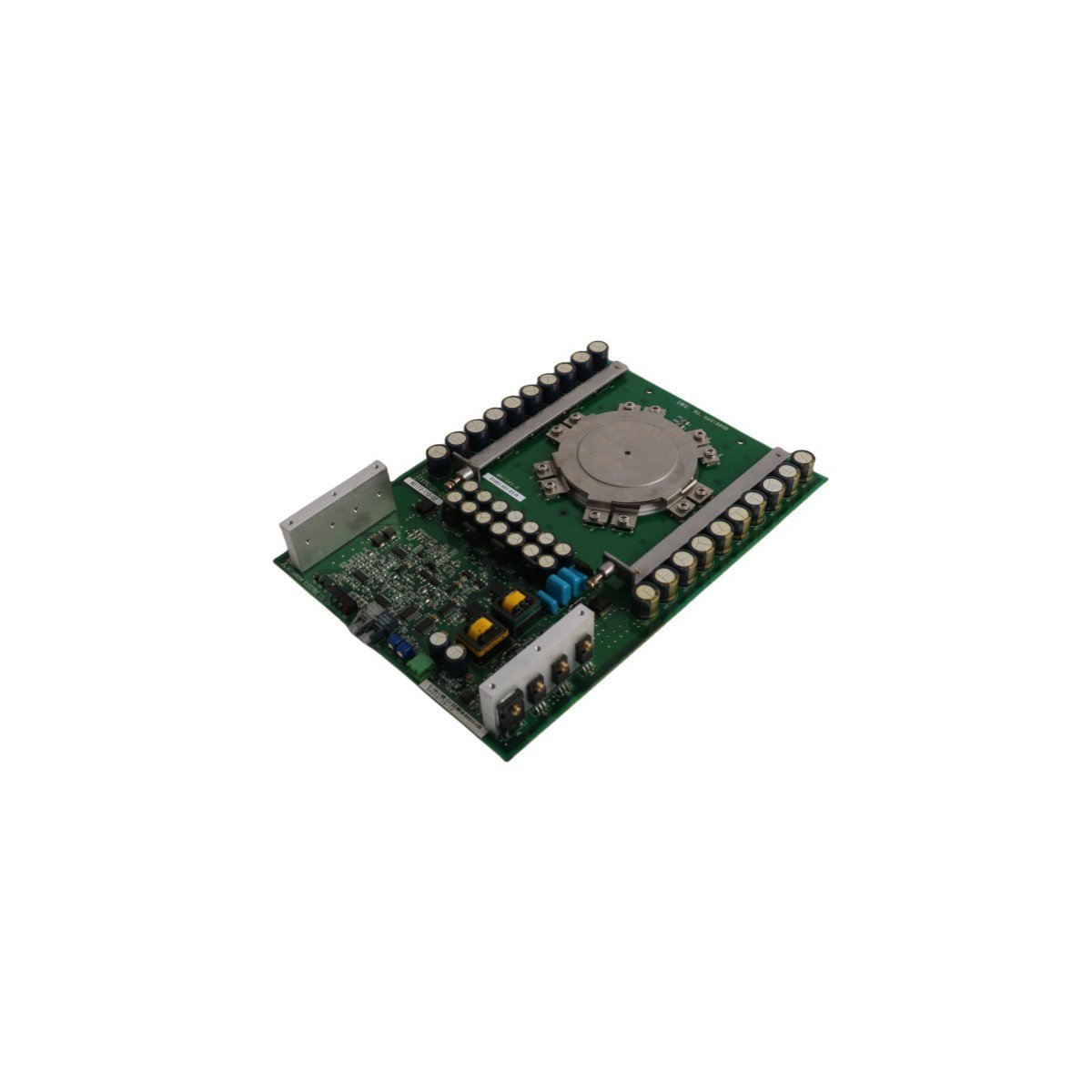
The Allen Bradley 81001-451-62-R, also cataloged as the 81001-451-62-R 1500 Amp SGCT Matched Set, operates as a dedicated hardware component for high-current semiconductor switching and power regulation within medium voltage industrial drive systems.
The module integrates directly into high-power inverter assemblies, utilizing backplane bus communication velocity and EtherNet/IP deterministic networks to maintain synchronized gate firing sequences. The factory-matched symmetrical gate commutated thyristor (SGCT) arrangement preserves uniform current distribution across parallel semiconductor junctions. Internal firmware flash compatibility ensures seamless coordination with main system power processors, optimizing gate pulse timing and preventing localized thermal hotspots during full load execution.
Frequently Asked Questions
Q: Why must SGCT components be replaced as a matched set?A: Matched sets are calibrated at the factory to exhibit identical forward voltage drop and turn-on/turn-off switching characteristics. Replacing individual devices instead of the full matched set causes uneven current distribution, leading to premature semiconductor breakdown.Q: What precautions should be taken regarding drive bus discharge before handling?A: High-voltage DC bus capacitors connected to the assembly must be fully discharged and verified with a calibrated multimeter before physical removal or installation to prevent severe electrical shock or component destruction.
Field Installation Guidelines
Verify that all main incoming three-phase AC power and auxiliary control power feeds are disconnected, locked out, and tagged prior to accessing the enclosure.
Handle the matched SGCT devices using proper ESD protection protocols, including a grounded wrist strap attached to the metal frame of the drive enclosure.
Inspect thermal contact surfaces for contaminants; apply a thin, uniform layer of specified thermal conductive grease before mounting to the heatsink.
Use a calibrated torque wrench to tighten mounting hardware according to specified mechanical tolerances to ensure proper electrical contact and thermal dissipation.
Route gate driver signal cables away from high-current busbars to mitigate electromagnetic interference and false firing signals.
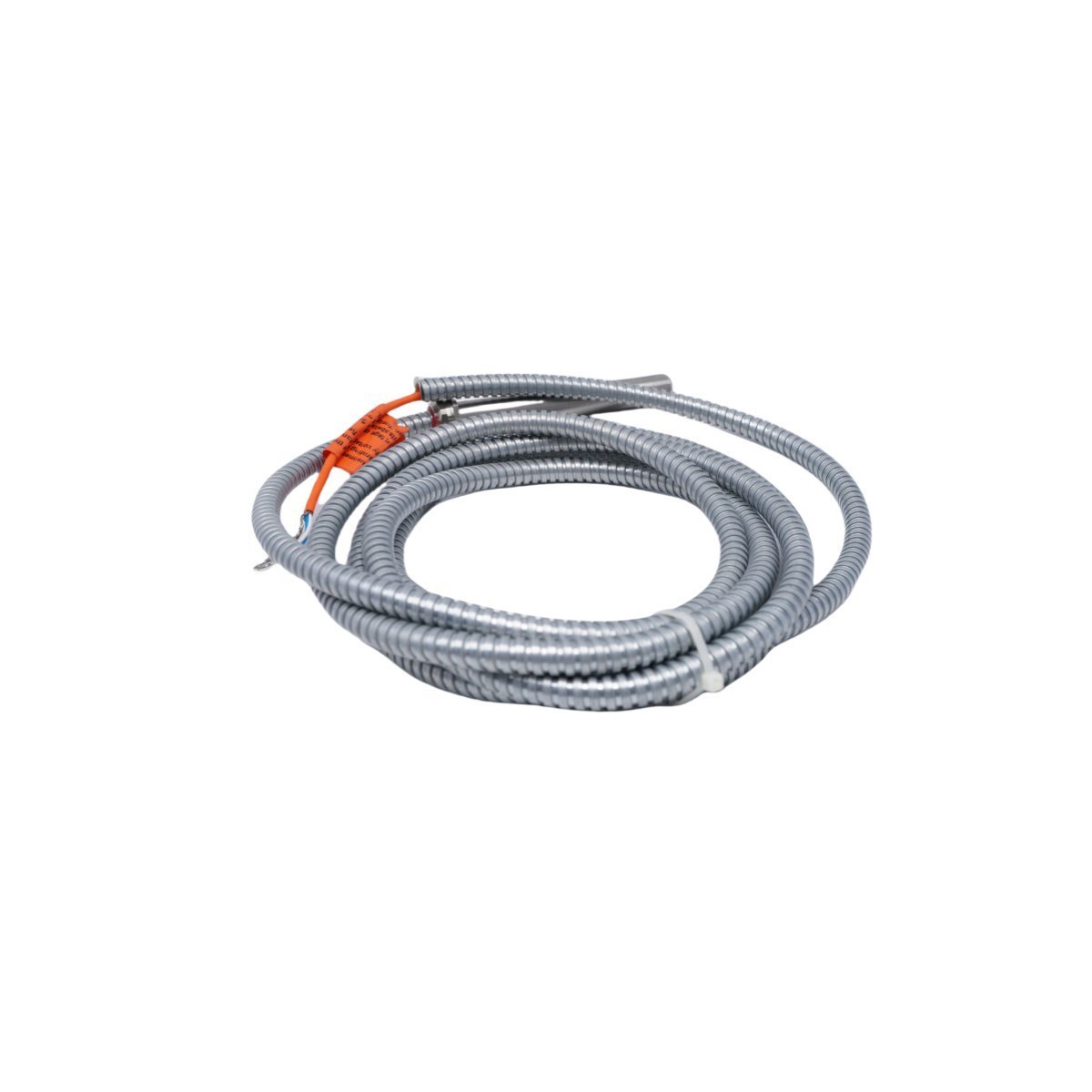
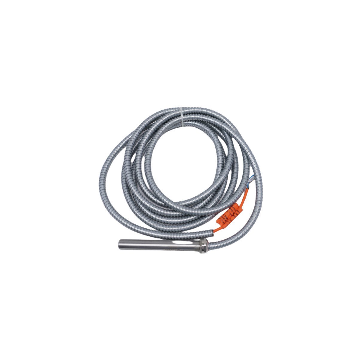
The Emerson PR9376/010-001, also cataloged as the PR9376/010-001 EPRO Module New, operates as a dedicated hardware component for analog process signal conditioning and control loop execution within distributed control platforms.
Hardware Specifications
Parameter
Specification
Model
PR9376/010-001
Brand
Emerson
Origin
USA
Weight
0.66 kg
Dimensions
4.4 x 17.8 x 11.4 cm
Operating Temp
0 deg C to 60 deg C
Power Consumption
24 VDC nominal
Process Loop Integration and Signal Isolation
The module processes analog inputs through dedicated signal conversion channels while maintaining channel-to-channel isolation to prevent electrical interference across loops. The internal circuitry supports 4-20 mA HART loop protocol integration for remote transmitter calibration and real-time diagnostic polling. Cold junction compensation (CJC) maintains thermocouple measurement accuracy across ambient temperature shifts, while FOUNDATION Fieldbus communication layers execute deterministic field device updates without loop degradation.
Frequently Asked Questions
Q: Does the module support live insertion and removal under power?A: System backplane specifications dictate whether hot-swapping is permitted; verify rack-level power status before extracting the module to prevent backplane bus faults.Q: How are field wiring errors isolated from internal processor components?A: Channel-to-channel galvanic isolation circuits prevent transient overvoltages from propagating across adjacent analog input channels or damaging internal logic planes.
Field Installation Guidelines
Mount the unit securely within designated enclosure slots, ensuring that shielded twisted-pair cables terminate at the proper grounding bars to minimize electromagnetic interference. Verify loop supply voltage levels prior to terminal block connection to protect analog input stages against overvoltage conditions.
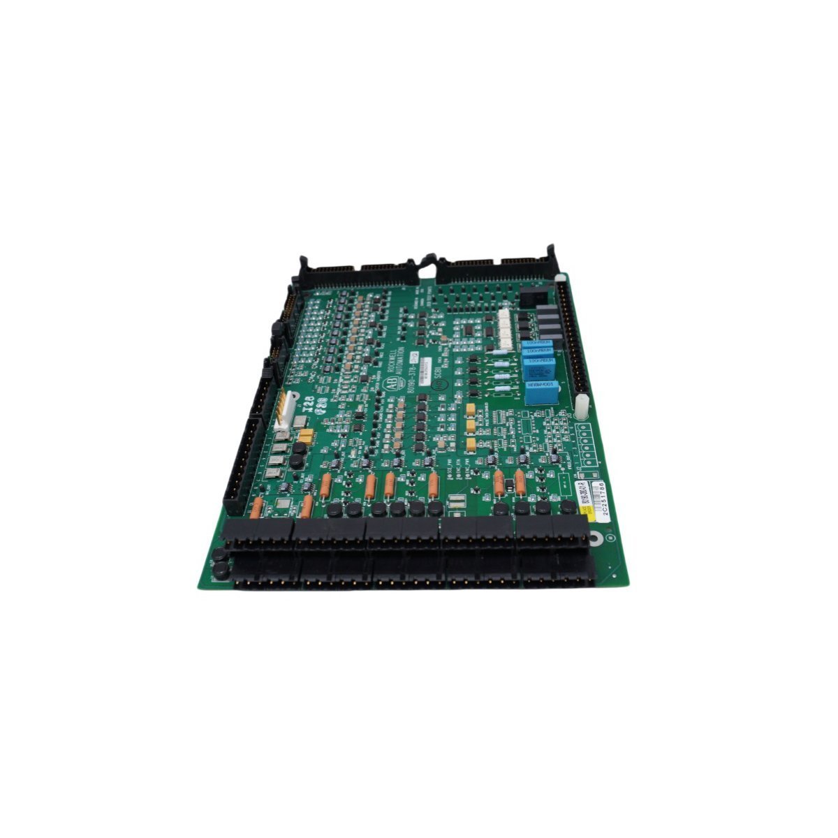
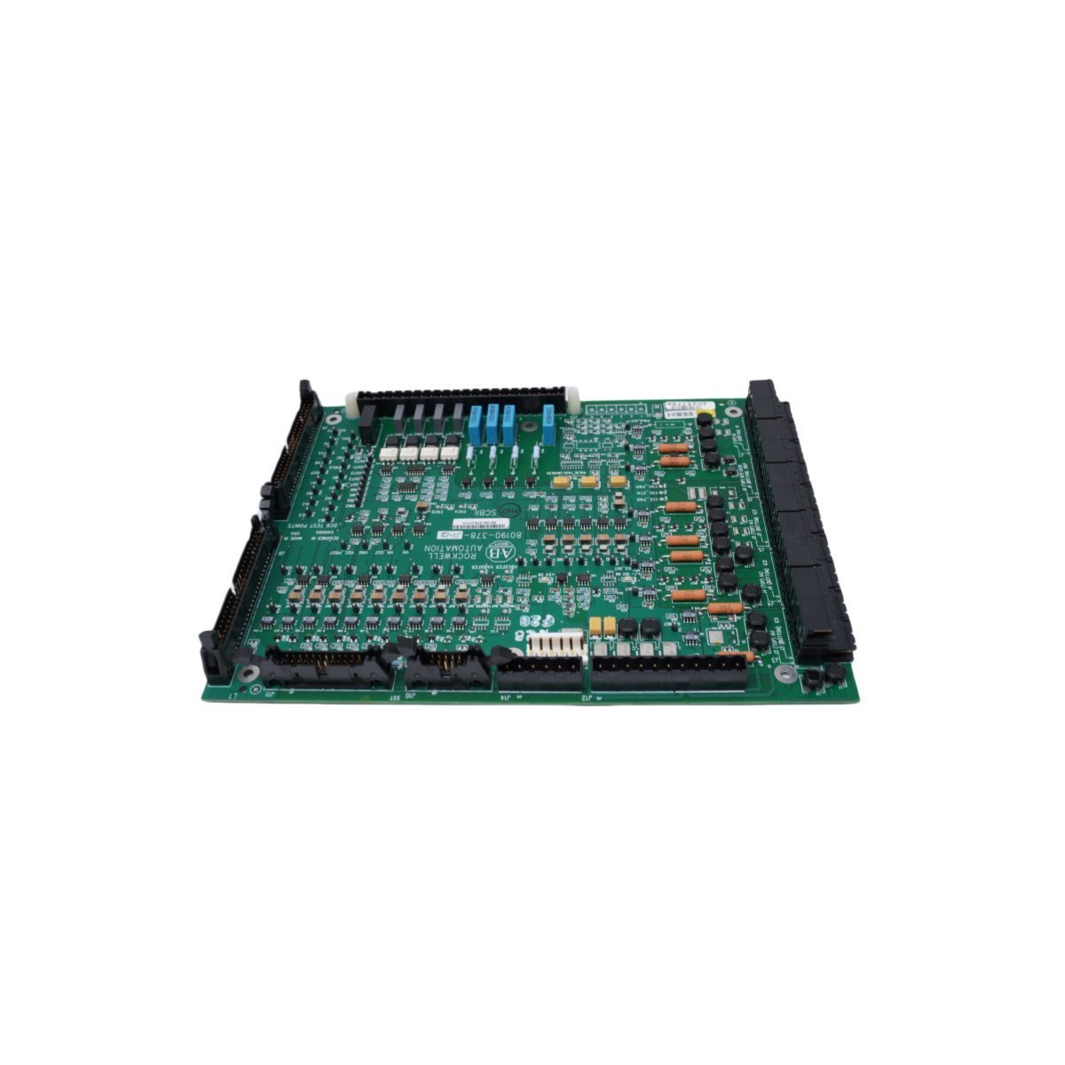
The Allen Bradley 80190-378-51, also cataloged as the 80190-378-51 PC Board, operates as a dedicated hardware component for signal processing and logic execution within PLC-5 platform networks.
Hardware Specifications
Parameter
Specification
Model
80190-378-51
Brand
Allen Bradley
Origin
USA
Weight
0.46 kg
Dimensions
27.8 x 21.4 x 2.8 cm
Operating Temp
Standard Industrial Range
Power Consumption
System Dependent
Module Type
PC Board
PLC Deterministic Network Integration
The Allen Bradley 80190-378-51 utilizes backplane bus communication protocols designed for integration with PLC-5 control architectures. The module supports deterministic network timing, ensuring low-latency state feedback and synchronization within complex I/O density configurations. Compatibility with field-programmable firmware allows for flash updates to align with evolving backplane bus communication velocity requirements, maintaining bus traffic integrity and reducing collision potential in high-speed control loops.
Frequently Asked Questions
Q: What are the restrictions regarding the installation of the 80190-378-51 in an active PLC-5 backplane?A: Ensure that the backplane power is cycled off before insertion or removal to prevent electrical arcing on the connector pins. The module must be correctly seated in the chassis slot to maintain signal integrity across the backplane bus.Q: Is this module capable of firmware field-upgrades?A: Yes, the unit supports firmware flash compatibility via the primary control bus interface. Verify the current revision against the specific PLC-5 processor requirements before initiating any update sequence.
Field Installation Guidelines
Mount the PC Board into a standard PLC-5 chassis. Ensure the mounting screws are tightened to the specified torque to guarantee a secure electrical chassis ground connection.
Avoid exposing the component to electrostatic discharge (ESD). Utilize a grounded wrist strap when handling the board.
Ensure all backplane pins are free of debris or oxidation before installation.
Maintain ambient operating temperature within the specified industrial limits to prevent thermal degradation of on-board components.
Verify that the backplane power supply capacity is sufficient for the total I/O density load when the module is initialized.
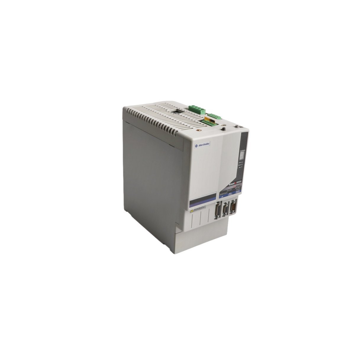
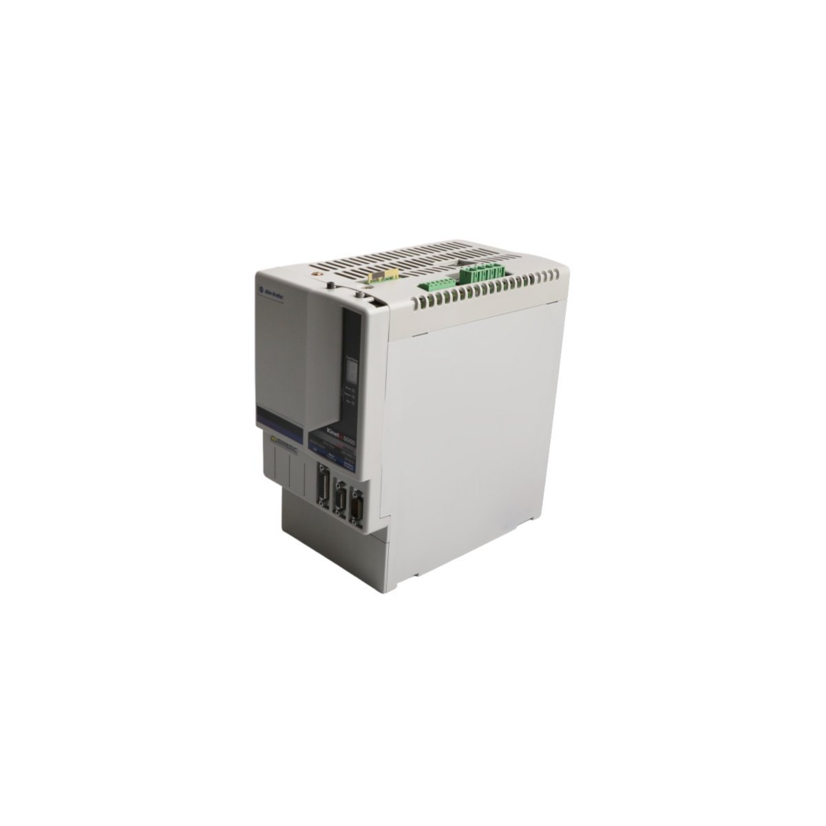
Configured for high-performance motion control in Kinetix 6000 multi-axis drive systems, the Allen-Bradley 2094-BM03-S (2094-BM03-S Axis Module) provides direct physical and electrical execution for rotary and linear motor regulation.
Hardware Specifications
Parameter
Specification
Model
2094-BM03-S
Brand
Allen-Bradley
Origin
USA
Weight
0.9 kg
Dimensions
3.5 cm x 13 cm x 14.5 cm
Operating Temp
Standard industrial range
Power Consumption
200 W continuous (dissipation)
Continuous Current
21.2 A
Peak Current
53.0 A
Power Output
13.5 kW
Industrial Control System Connectivity
The 2094-BM03-S integrates into industrial control platforms by utilizing high-speed backplane bus communication protocols for real-time motion synchronization. This modular architecture facilitates I/O density scaling within the drive cabinet, which allows the system to manage complex motion feedback loops efficiently. Furthermore, the module supports firmware flash compatibility, enabling engineers to update internal logic for specific application requirements. Consequently, the drive ensures deterministic response times during acceleration, deceleration, and power threshold excursions.
Frequently Asked Questions (FAQ)
Q: Does this axis module support hot-swapping within the Kinetix 6000 power rail?A: No, you must isolate the drive system from all primary power sources and verify that the DC bus is fully discharged before you remove or insert the module to prevent damage to the backplane interface.Q: How does the module handle feedback signal integration?A: The 2094-BM03-S interfaces directly with motor feedback cables, processing auxiliary encoder signals to maintain precise position tracking and velocity regulation during operation.
Field Installation Guidelines
To begin with, ensure all power to the drive assembly is strictly isolated and that the DC bus voltage has dissipated to a safe level;Â consequently, this prevents accidental electrical discharge during handling.
Subsequently, mount the module onto the dedicated Kinetix power rail;Â furthermore, ensure that the mechanical locking tabs engage securely to provide the necessary ground contact and structural stability.
In addition, connect the motor feedback cables and interface wires to the front-panel terminals, ensuring that all shields are terminated at the designated ground lugs to suppress electromagnetic interference;Â meanwhile, verify the cable bend radius to prevent permanent fiber or conductor damage.
Following physical mounting, perform a thorough check of all electrical connections before applying system power;Â by doing so, you minimize the risk of short-circuits on the backplane.
Finally, confirm that the motion controller configuration matches the physical addressing and firmware version of the 2094-BM03-S to enable stable data exchange and command execution on the bus.
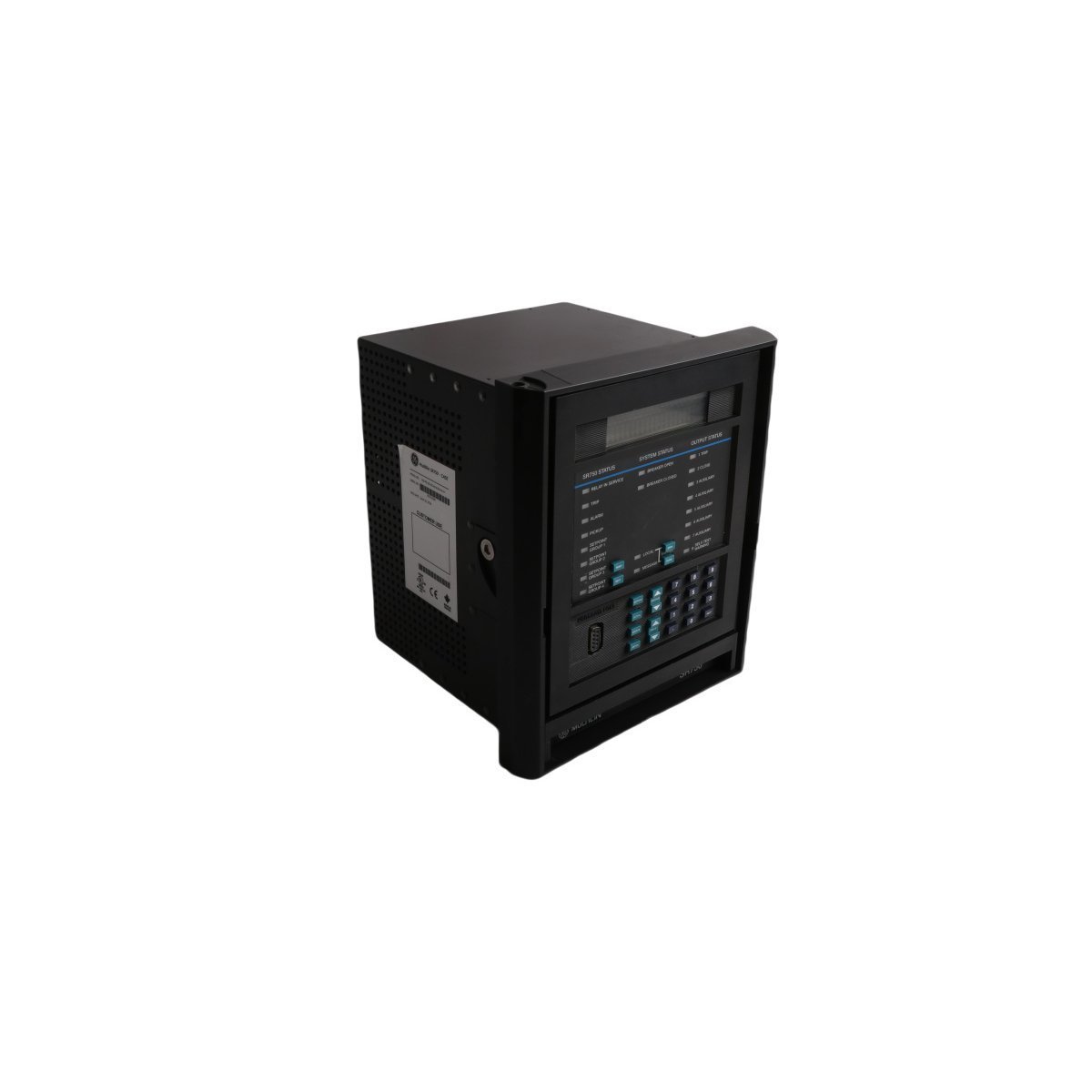
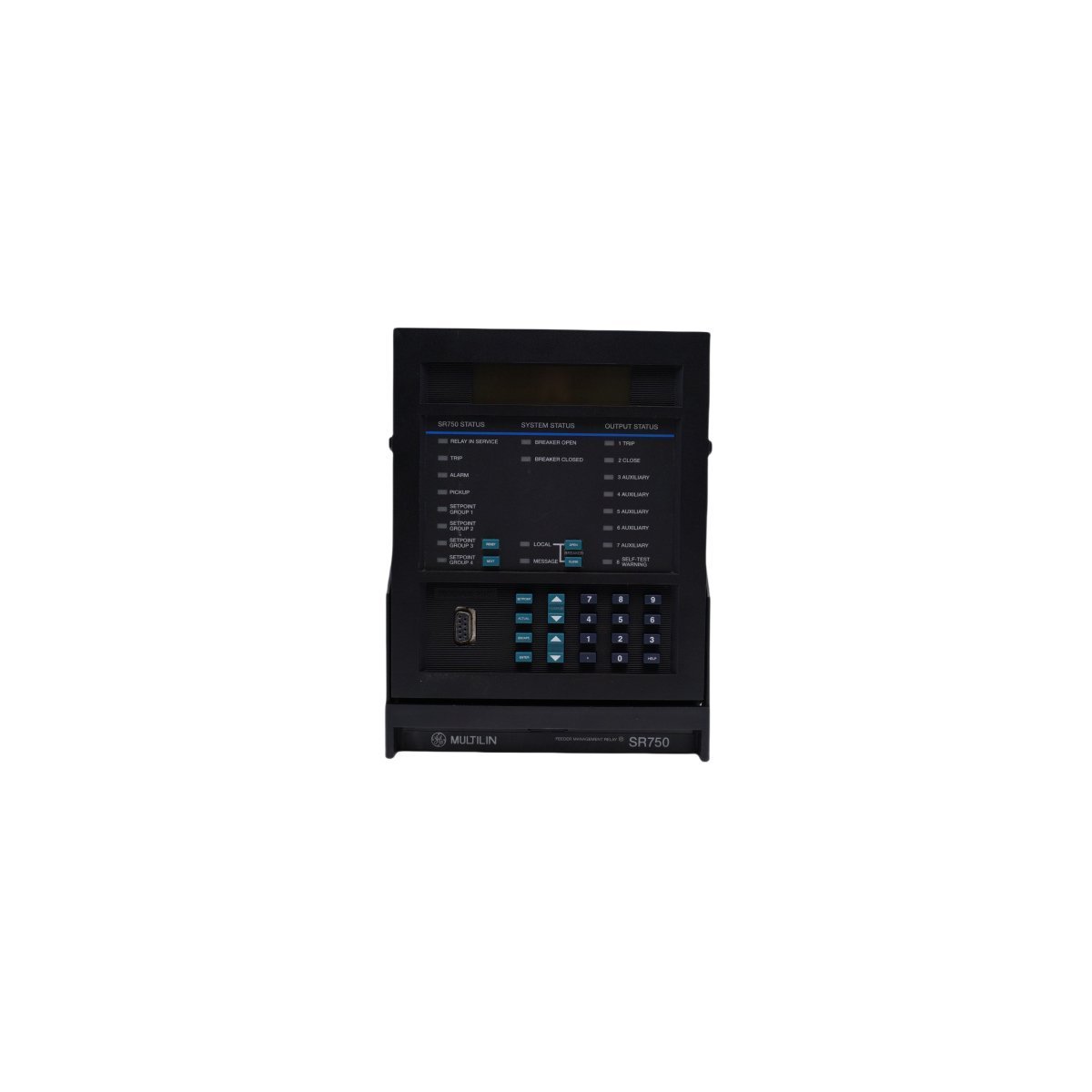
The GE 750-P5-G5-HI-A20-R is a robust Multilin feeder management relay featuring dual-processor architecture for precise protection and monitoring. This panel-mount device offers comprehensive metering, oscillography, and communication capabilities for critical distribution systems.
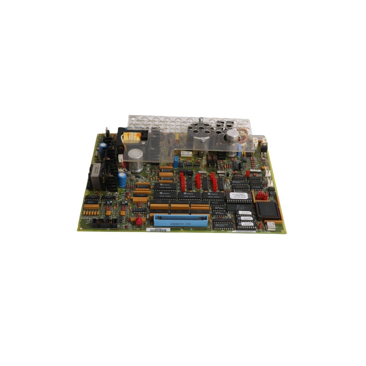
The GE DS200TCEAG1BTF is a dedicated Emergency Overspeed Board for the Mark V turbine control system. It features an integrated microprocessor and hardware-based protection to monitor turbine velocity and execute critical safety trip functions reliably.
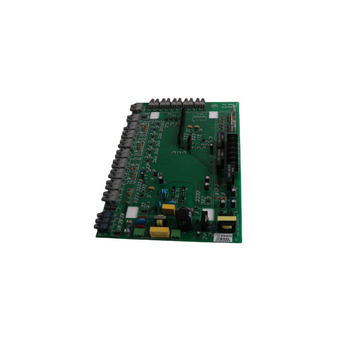
The Allen Bradley 80190-440-02-R interface board provides reliable signal management and logic control for SMC Flex soft starter motor protection systems.
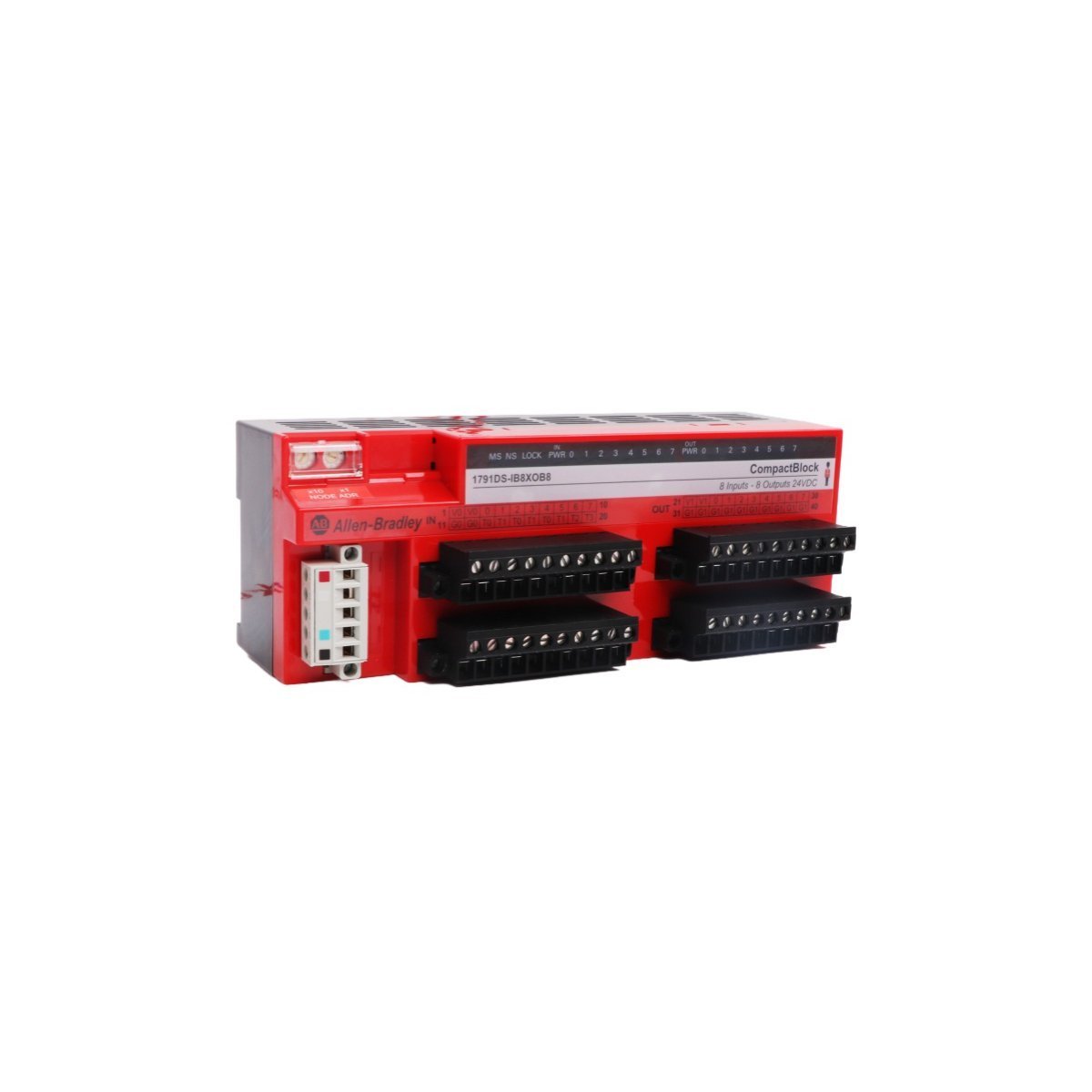
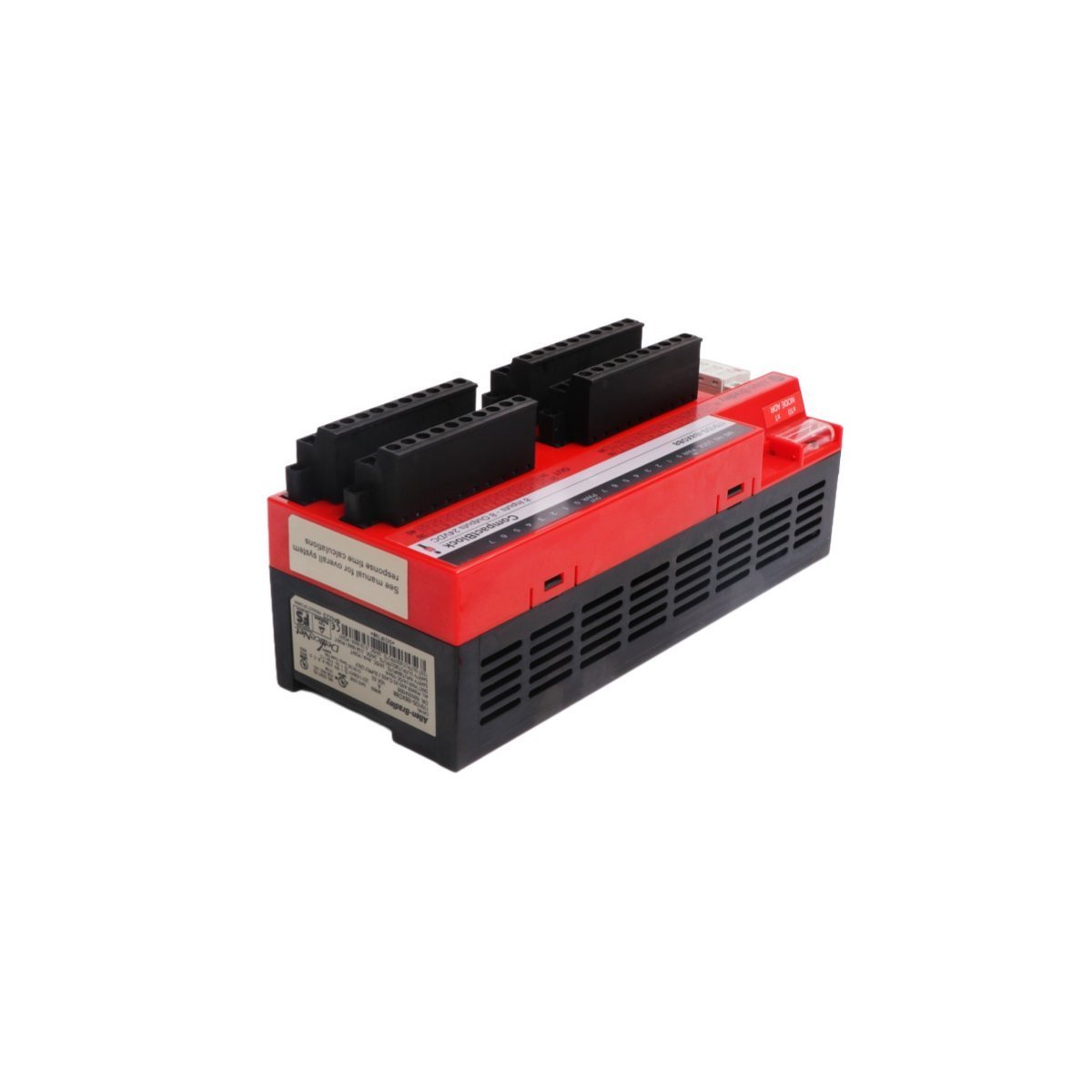
The Allen-Bradley 1791DS-IB8XOB8 is a 16-point Guard I/O safety combination block for DeviceNet networks. Featuring 8 safety inputs, 8 solid-state sourcing safety outputs, and 4 test outputs, this compact DIN-rail module delivers SIL 3 / Category 4 protection with onboard cross-fault diagnostics for machine safety applications.
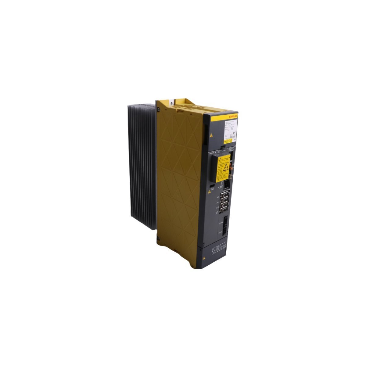
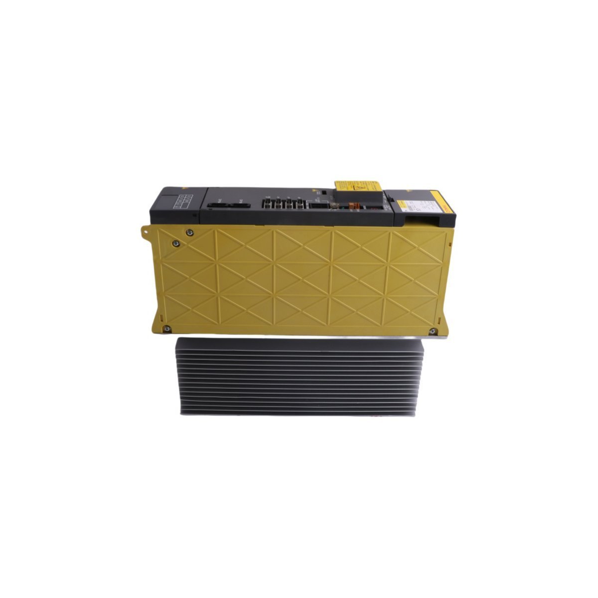
The General Electric A06B-6290-H106 is a FANUC αi series servo amplifier module designed for precision CNC motion control. It features micron-level accuracy, regenerative power management, and advanced diagnostics for high-speed machining and automation.
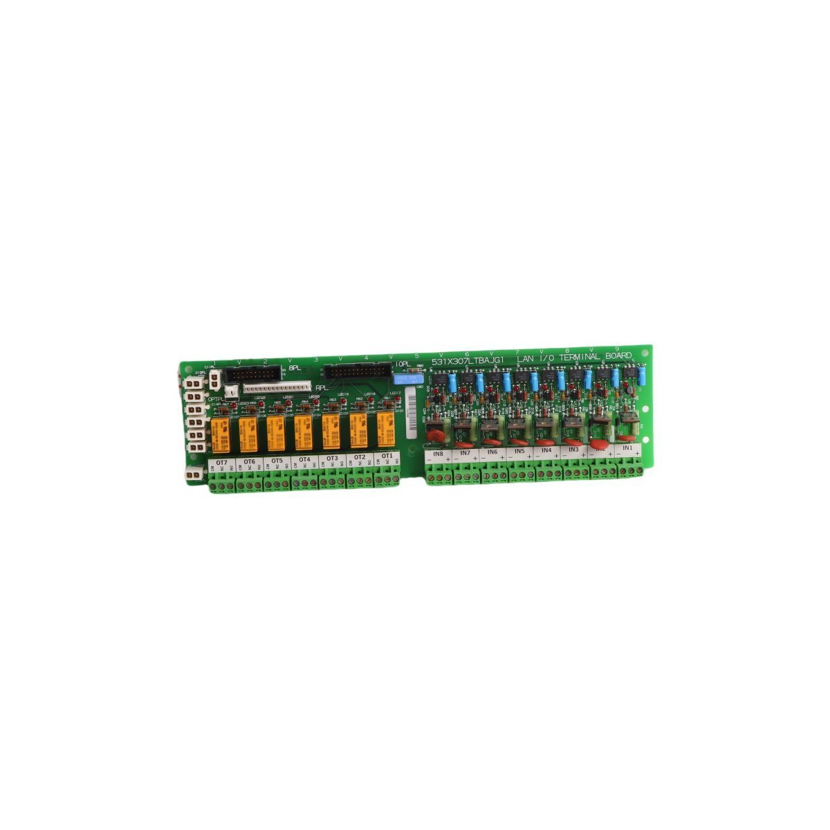
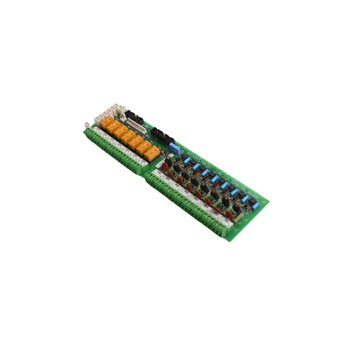
The GE 531X307LTBAKG1 is a Multilin series I/O Terminal Board designed for high-precision signal processing in GE drive systems. It supports RS-422 communication, encoder feedback, and features configurable hardware settings for specialized industrial automation tasks.
We are committed to protecting your privacy. The information collected here is strictly used to provide the requested quotes, technical support, and relevant industrial automation solutions.