Sale!
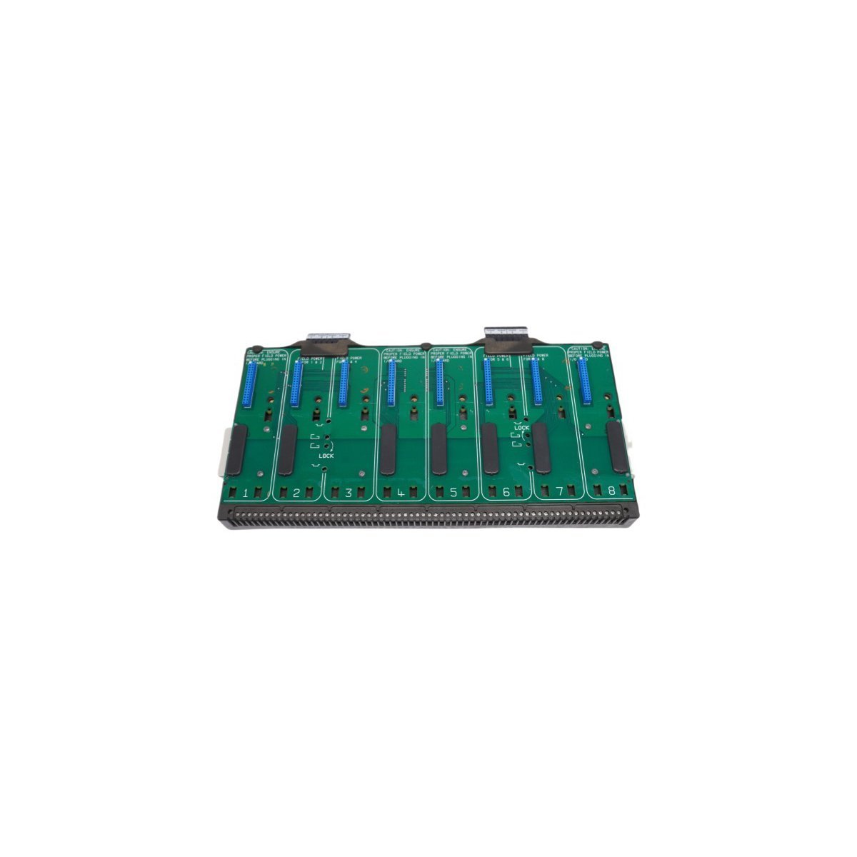
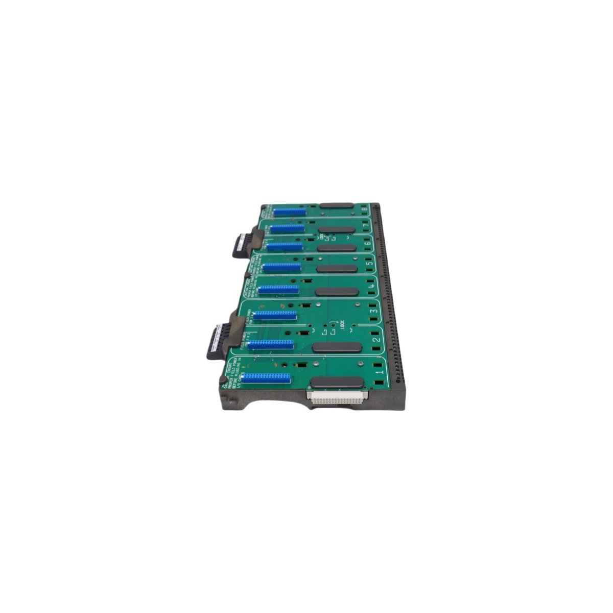
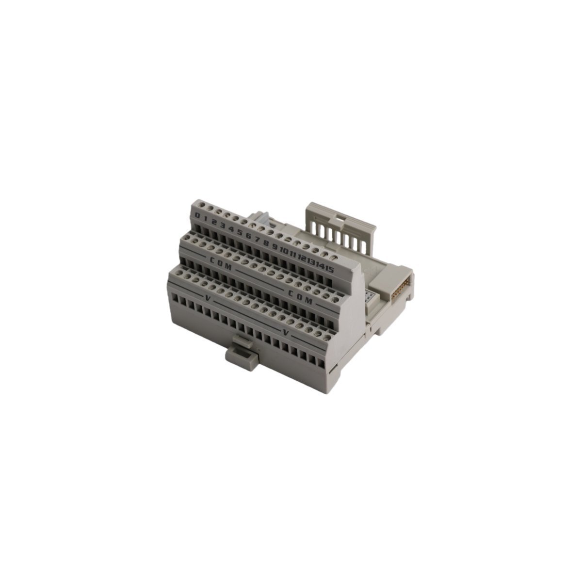
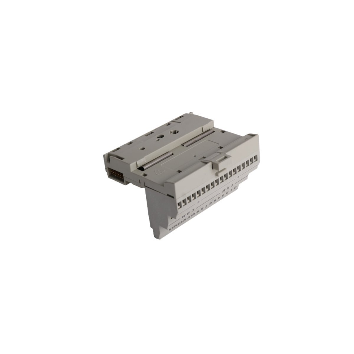
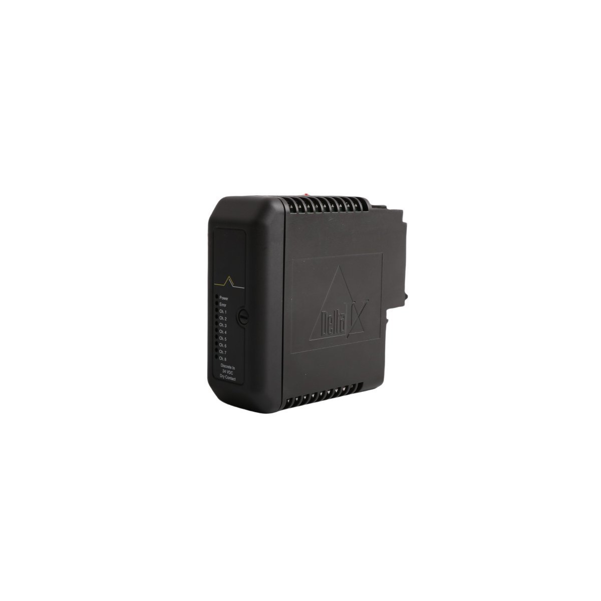
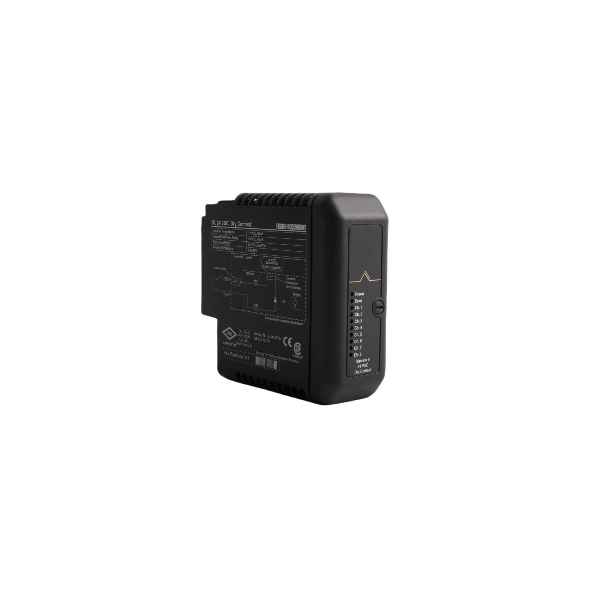
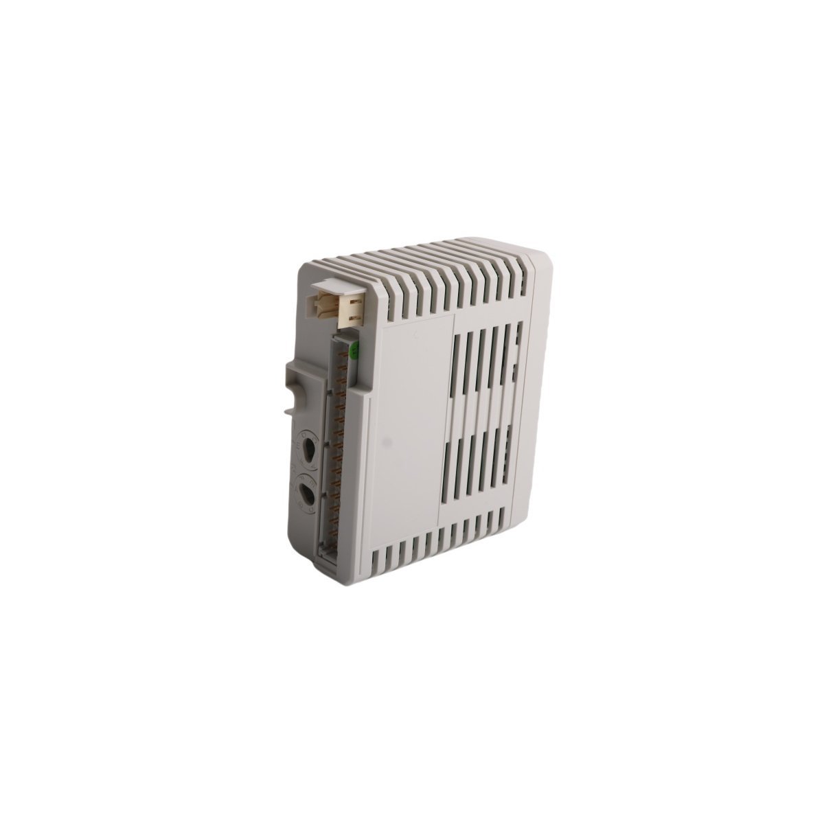
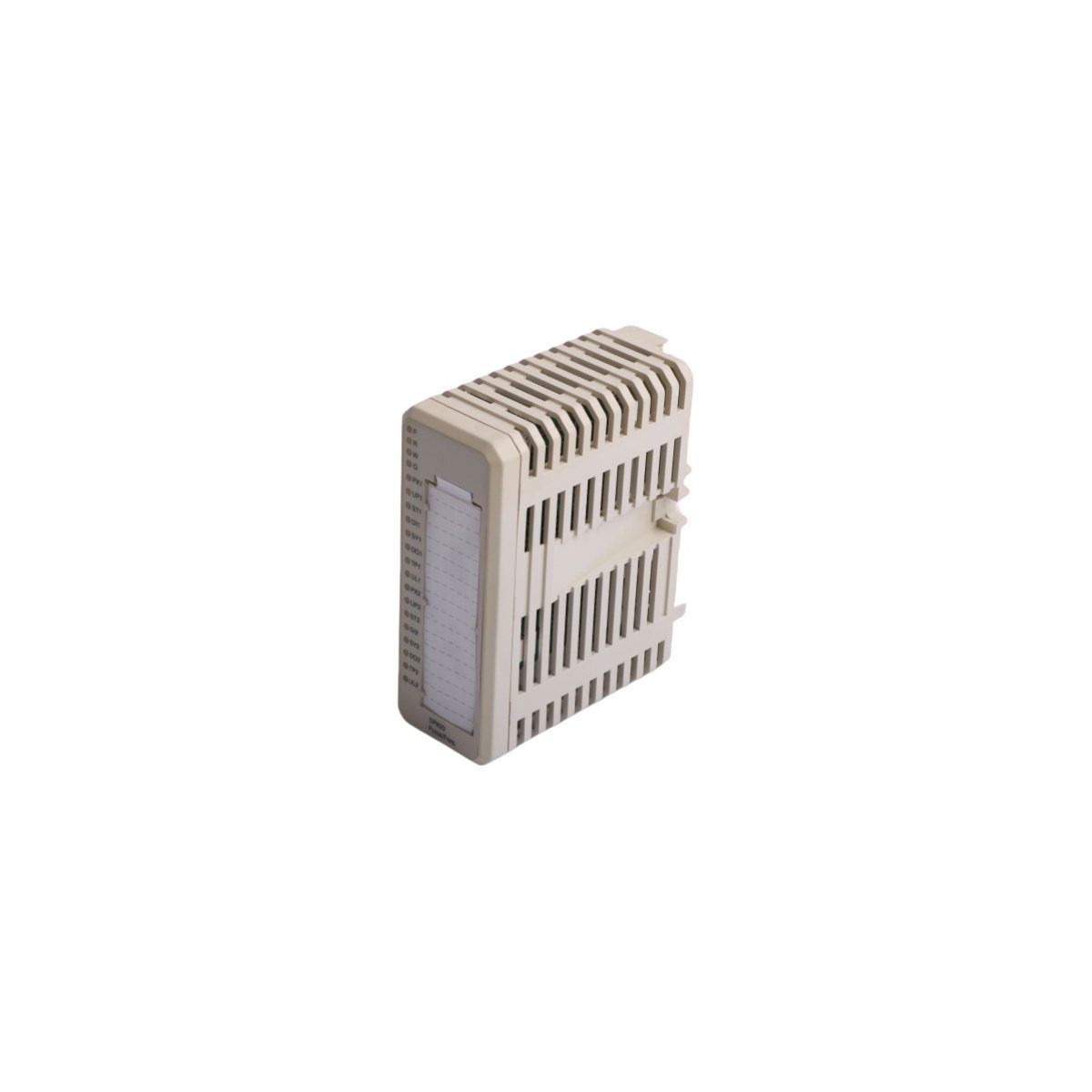
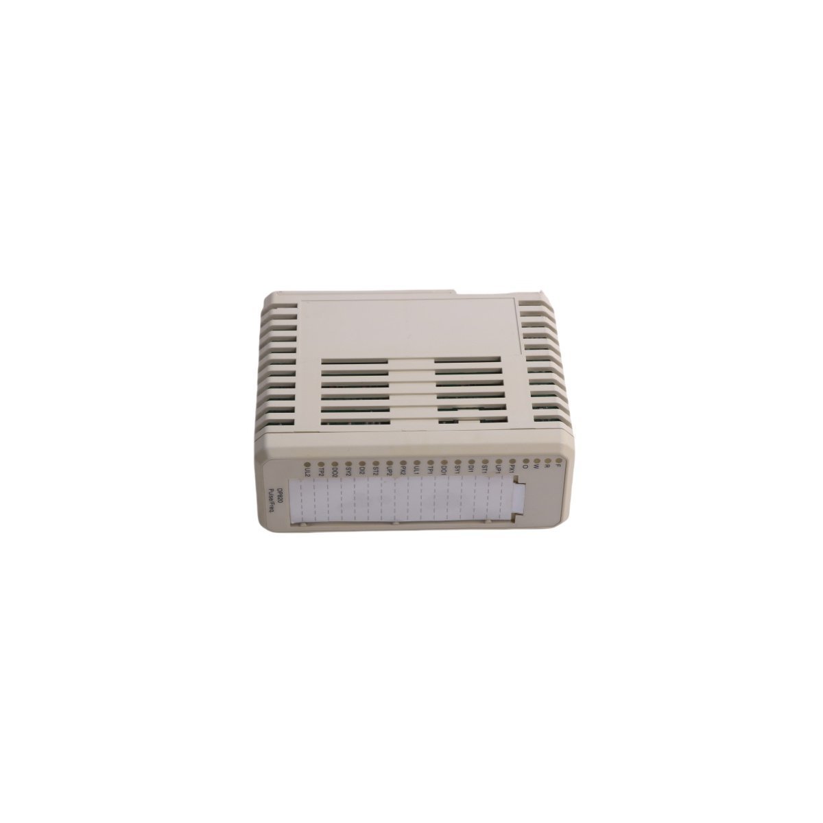
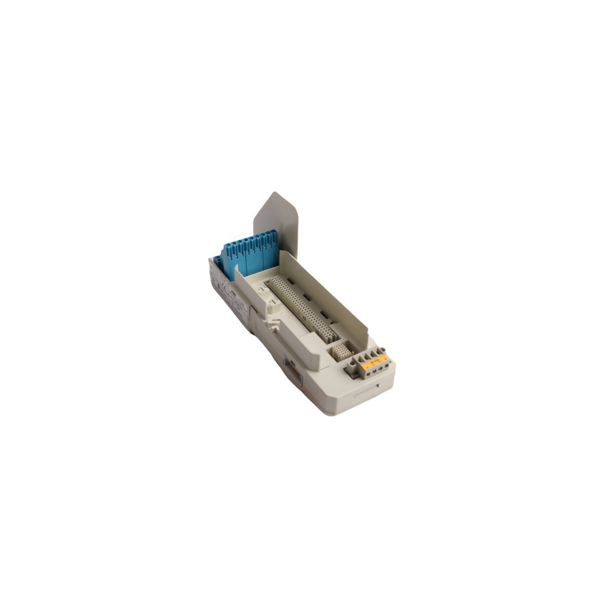
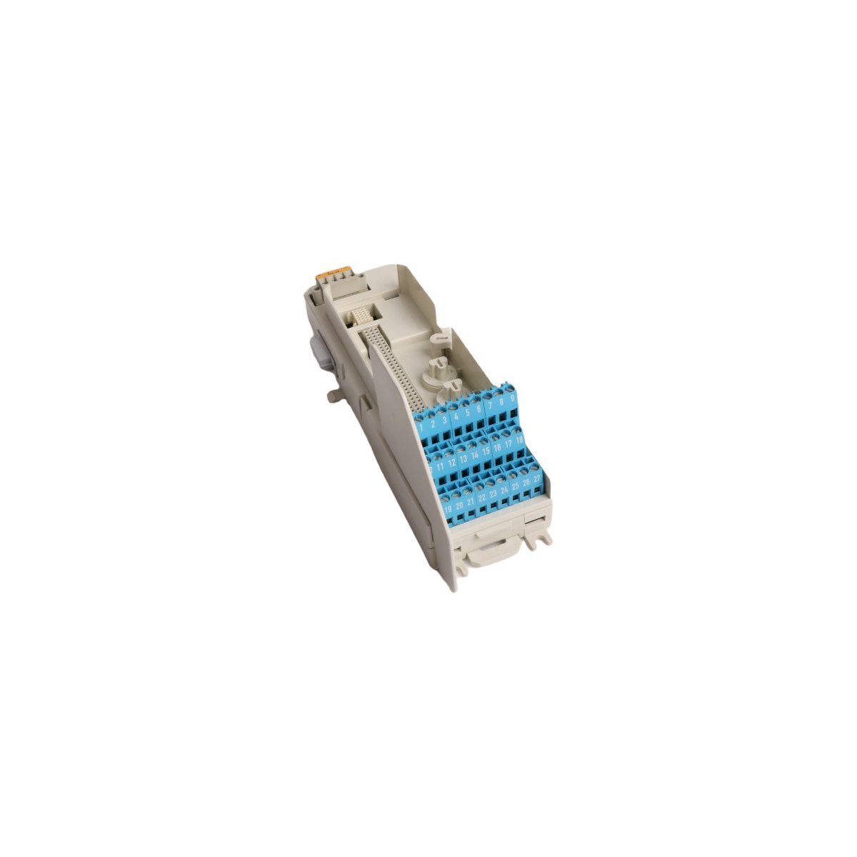
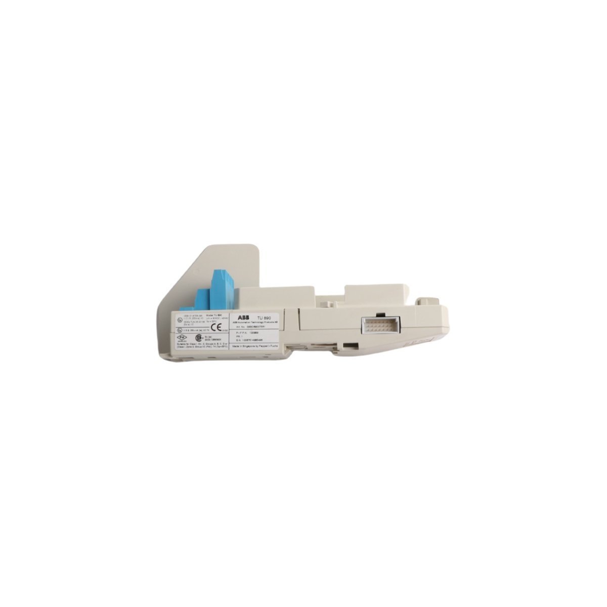
Emerson KJ4001X1-BE1 12P0818X072 8-Wide IO Carrier With Shield
Configured for high-density signal distribution in DeltaV M-series I/O Subsystem networks, the Emerson KJ4001X1-BE1 12P0818X072 (KJ4001X1-BE1 8-Wide IO Carrier) provides direct physical/electrical execution.
Suffix Breakdown & Model Matrix
| Model | Description |
|---|---|
| KJ4001X1-BE1 | DeltaV M-series 8-wide I/O carrier with integrated shielding |
| 12P0818X072 | Internal Emerson factory manufacturing reference code |
Hardware Specifications
| Parameter | Specification |
|---|---|
| Model | KJ4001X1-BE1 |
| Brand | Emerson |
| Origin | USA |
| Weight | 0.72 kg |
| Dimensions | 34.7 x 17 x 3.3 cm |
| Operating Temp | Standard industrial range |
| Power Consumption | Passive bus backplane |
| System Compatibility | DeltaV M-series |
Process Control & Connectivity
The KJ4001X1-BE1 acts as the physical backbone for M-series I/O card mounting and signal termination. This carrier features a shielded design to isolate backplane communications from external electromagnetic interference (EMI). It supports 8-wide module placement, facilitating high-density I/O configurations while maintaining strict electrical separation between signal loops. The carrier integrates with the DeltaV system bus to manage data throughput and power distribution across all installed I/O modules. Users must adhere to proper shielding ground practices to ensure the 4-20 mA HART loop protocol signals maintain their rated accuracy during transmission.Frequently Asked Questions
Q: Does the carrier support hot-swapping of I/O modules?A: Yes, the DeltaV M-series backplane architecture supports the removal and insertion of I/O modules while the carrier is energized, provided the specific I/O module type allows for such operations under the defined safety and process conditions.Q: How does the integrated shielding function?A: The carrier incorporates a conductive chassis plane that connects to the system earth ground. This plane acts as an EMI shield for the underlying bus communication traces, preventing noise coupling into sensitive analog input circuits.Field Installation Guidelines
- Mount the carrier horizontally on a standard DIN-rail or chassis plate within the control cabinet.
- Verify that the carrier backplane ground lug connects securely to a low-impedance earth ground to satisfy EMI protection requirements.
- Ensure all I/O modules seat firmly into the connector slots to prevent backplane bus communication timeouts or intermittent signal loss.
- Maintain adequate clearance above and below the carrier to facilitate heat dissipation and cabling access.
- Inspect all terminal blocks for loose connections after installation to ensure low-resistance contact for all signal and power circuits.