Sale!
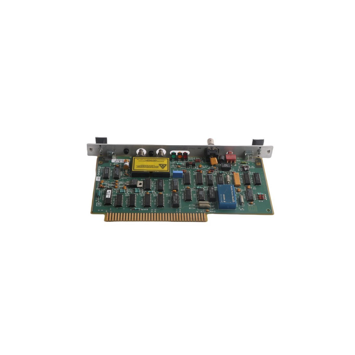
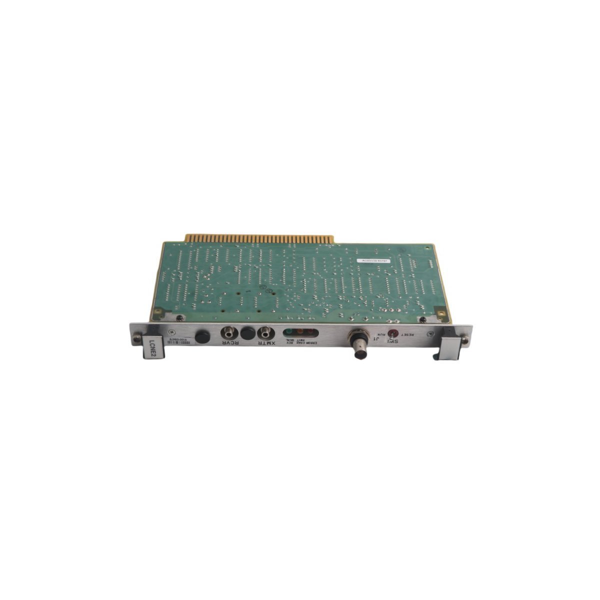
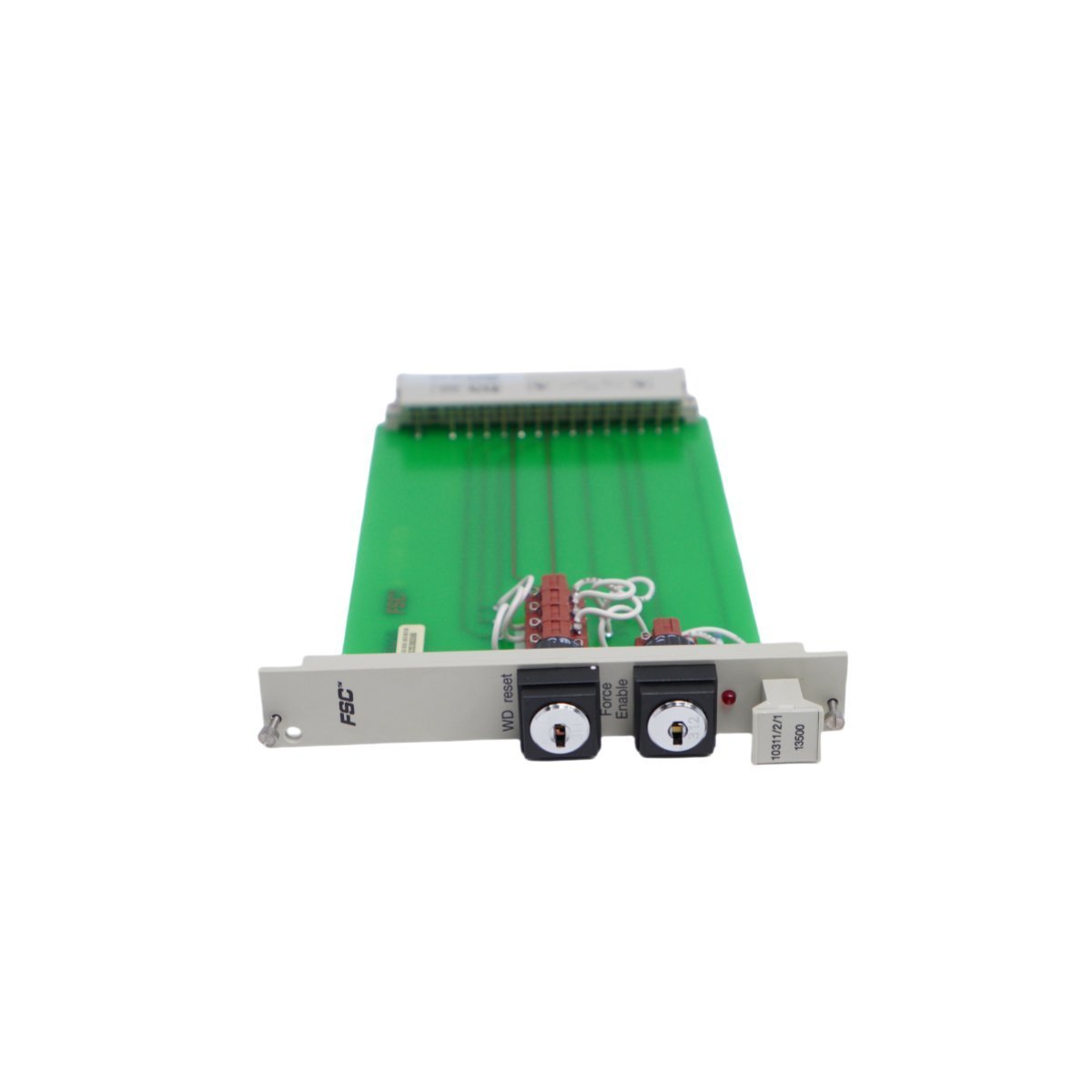
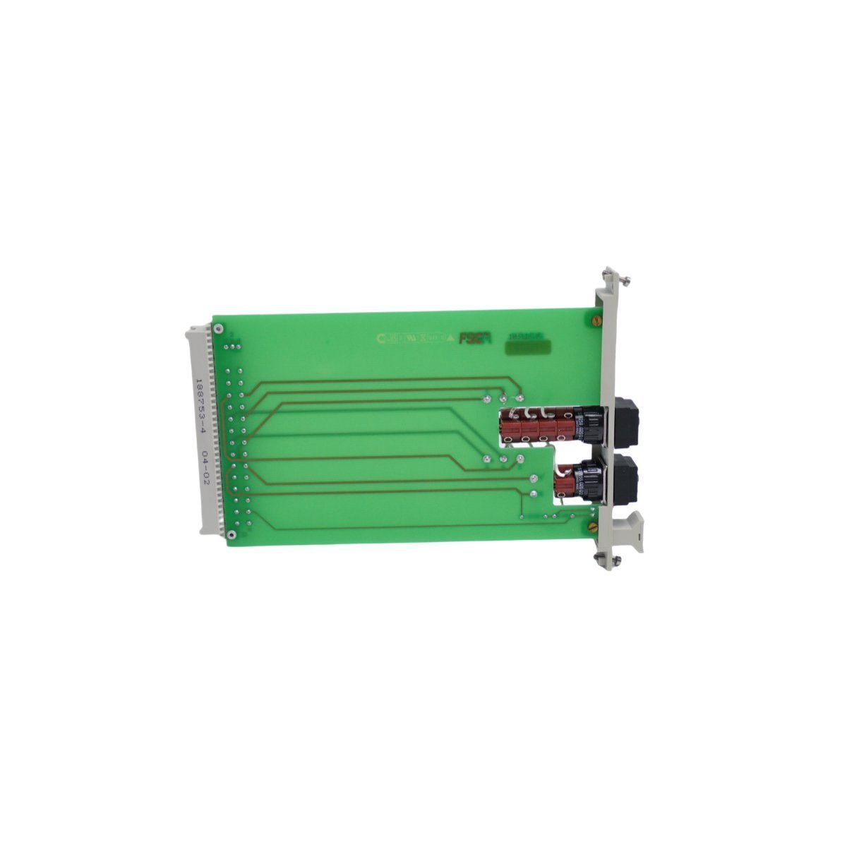
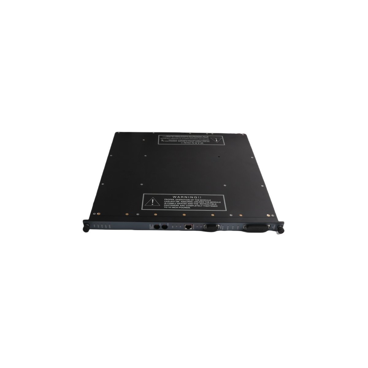
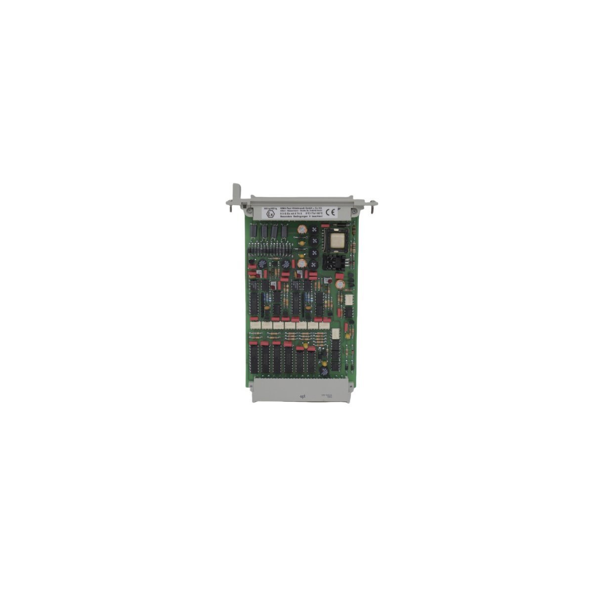
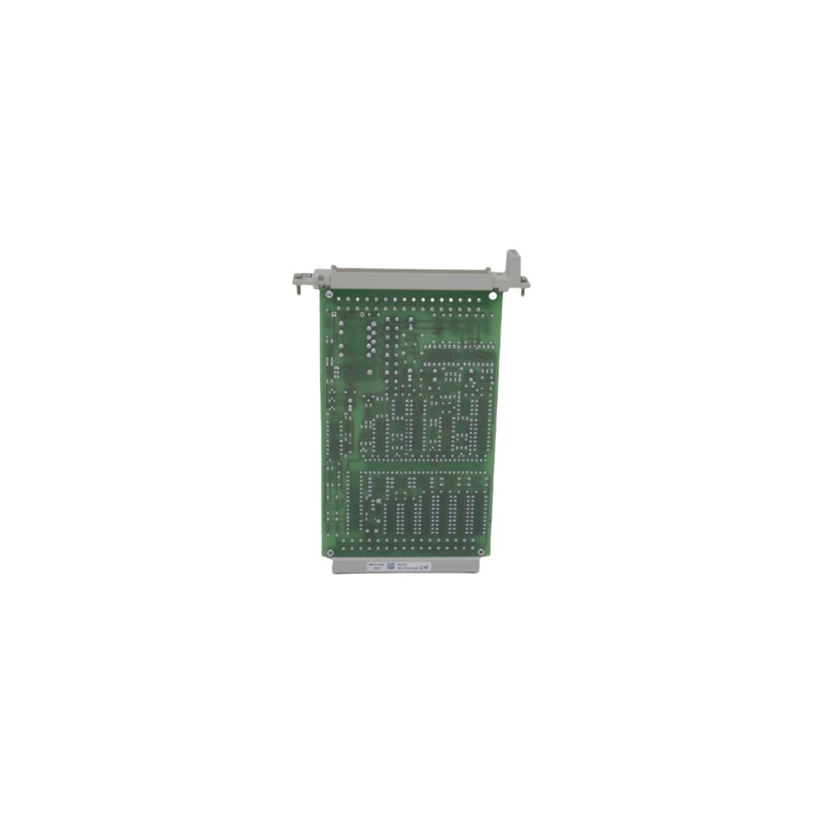
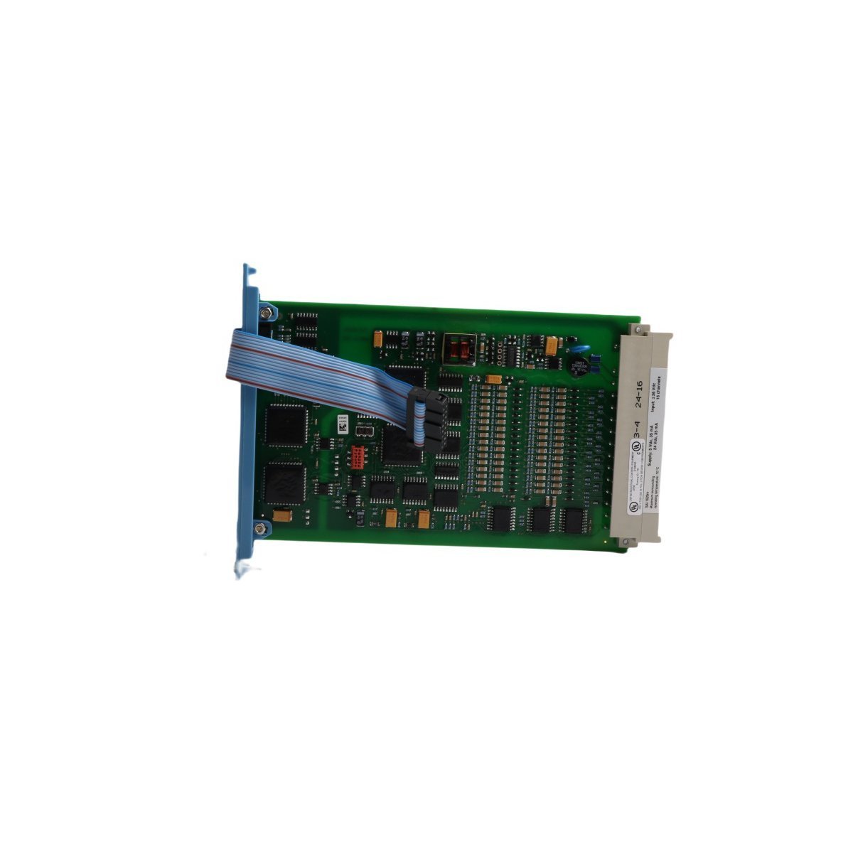
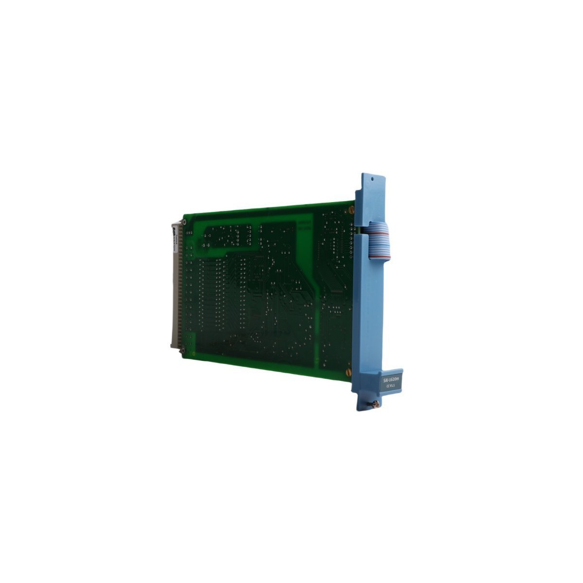
Honeywell 51304540-100 TDC 3000 Safety Manager Module
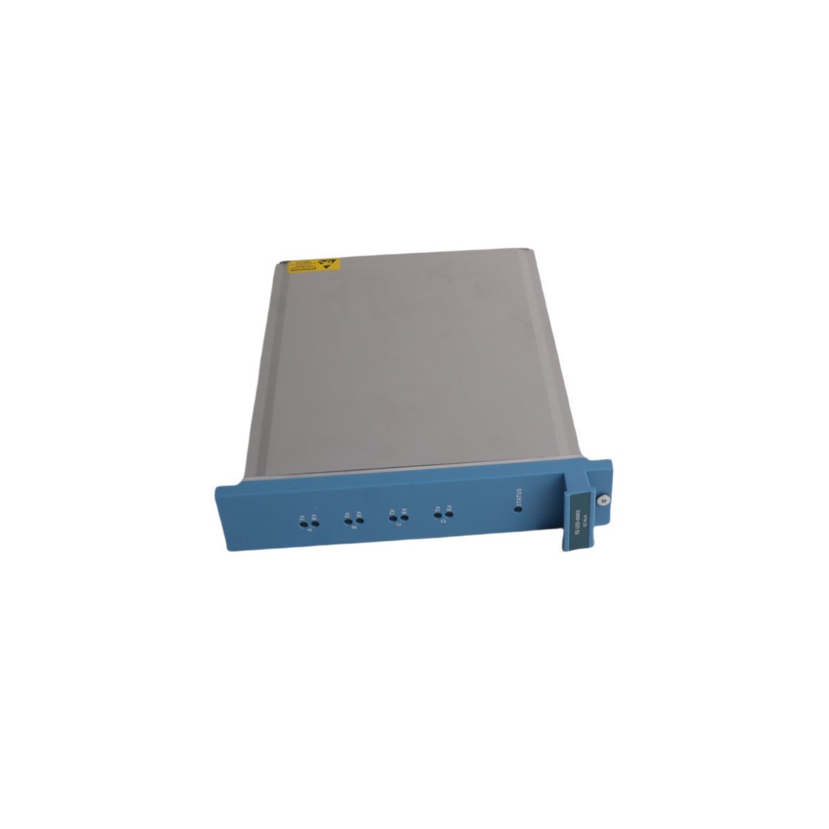
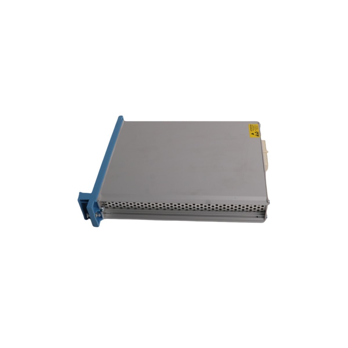
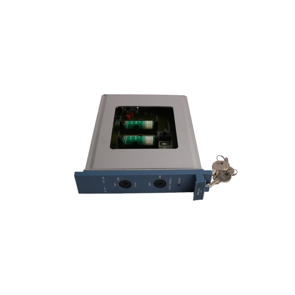
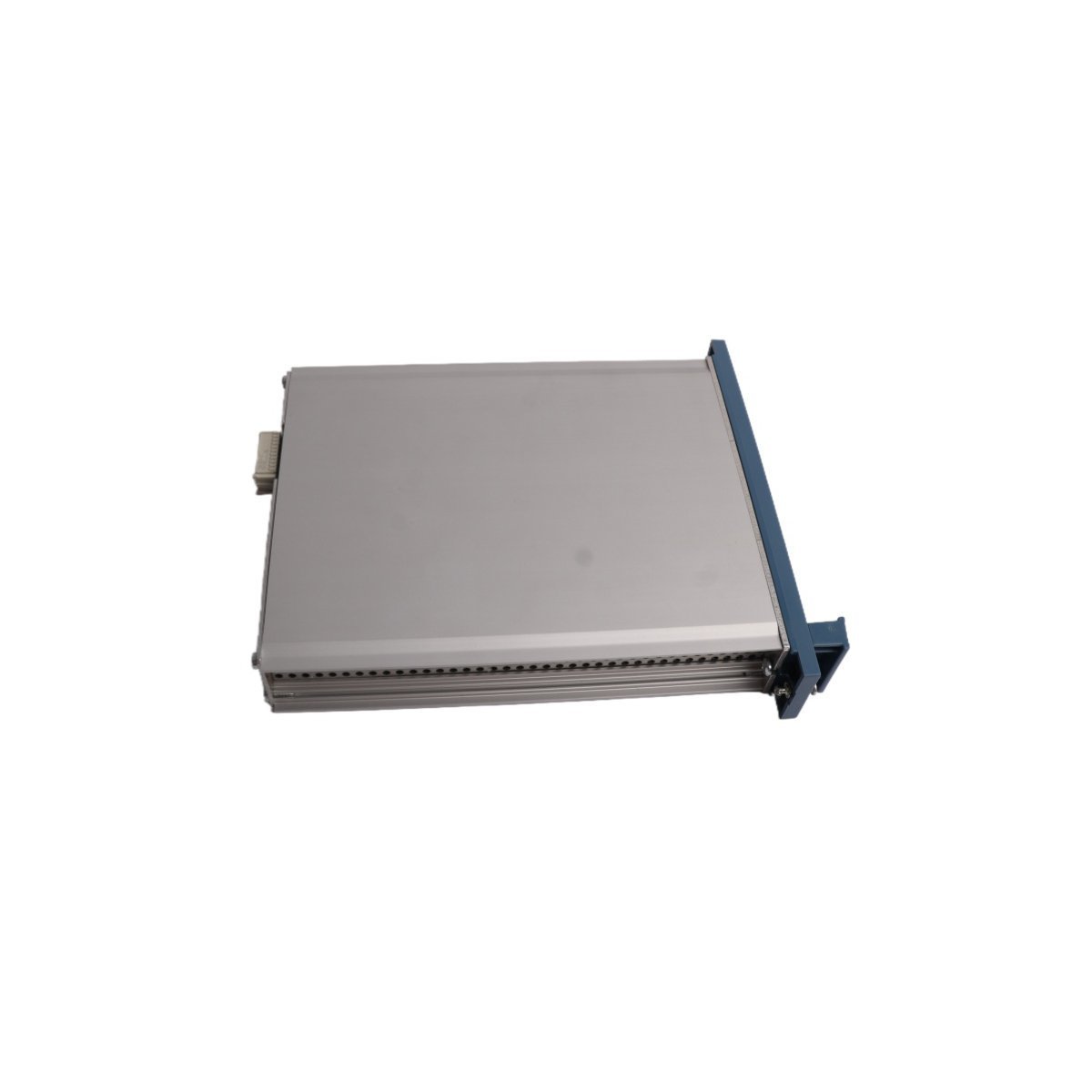
Configured for high-speed signal transmission and process data routing within TDC 3000 DCS platforms, the Honeywell 51304540-100 (51304540-100 Safety Manager Module) provides direct physical electrical execution for data acquisition and control command distribution.
Hardware Specifications
| Parameter | Specification |
|---|---|
| Model | 51304540-100 |
| Brand | Honeywell |
| Origin | USA |
| Weight | 0.24 kg |
| Dimensions | 2 x 13.5 x 23.8 cm |
| Operating Temp | Industrial standard |
| Power Consumption | System-bus dependent |
| Module Type | Safety Manager Module |
Process Control & Signal Characteristics
The 51304540-100 module operates as a primary interface within the Universal Control Network (UCN), where it manages data conversion and transmission via optical or electrical mediums.
The module utilizes channel-to-channel isolation to maintain signal integrity, which effectively prevents the propagation of ground loops or common-mode noise across the control network.
The architecture incorporates advanced conditioning logic to support real-time data throughput and ensures deterministic communication latency.
Furthermore, the module facilitates cold junction compensation (CJC) for integrated thermocouple inputs and maintains measurement accuracy across varying ambient thermal conditions in the cabinet.
Frequently Asked Questions (FAQ)
Q: Can this module be hot-swapped while the TDC 3000 rack is powered?A: The 51304540-100 is designed for operation in powered racks; however, users should consult the specific revision of the system installation manual to confirm firmware-level support for hot-insertion in the current cabinet configuration.Q: What are the primary grounding requirements for this module's interface?A: High-frequency signal shields must be terminated directly to the cabinet ground bus via a low-impedance path to ensure maximum noise immunity and protection against transient surges.Q: How is synchronization maintained during redundant module operations?A: Synchronization is managed by the backplane bus interface, which handles heartbeat signaling and state-machine alignment between the primary and secondary modules to ensure transparent failover.Field Installation Guidelines
- First, verify that the module keying is correctly aligned with the I/O carrier rails to prevent potential pin damage during insertion.
- Subsequently, confirm the backplane power is at a zero-energy state prior to module seating to prevent electrical arcing on the edge connectors.
- Meanwhile, tighten the captive faceplate fasteners to the specified torque to ensure proper chassis ground contact and mechanical stability.
- Furthermore, ensure all optical or electrical cabling is routed through designated cable management ducts to minimize mechanical strain on the module ports.
- Finally, perform a cold-start diagnostic sequence via the local control station to verify successful node communication and database integration.