You are here:
SKU: MC-IOLX02 51304419-150

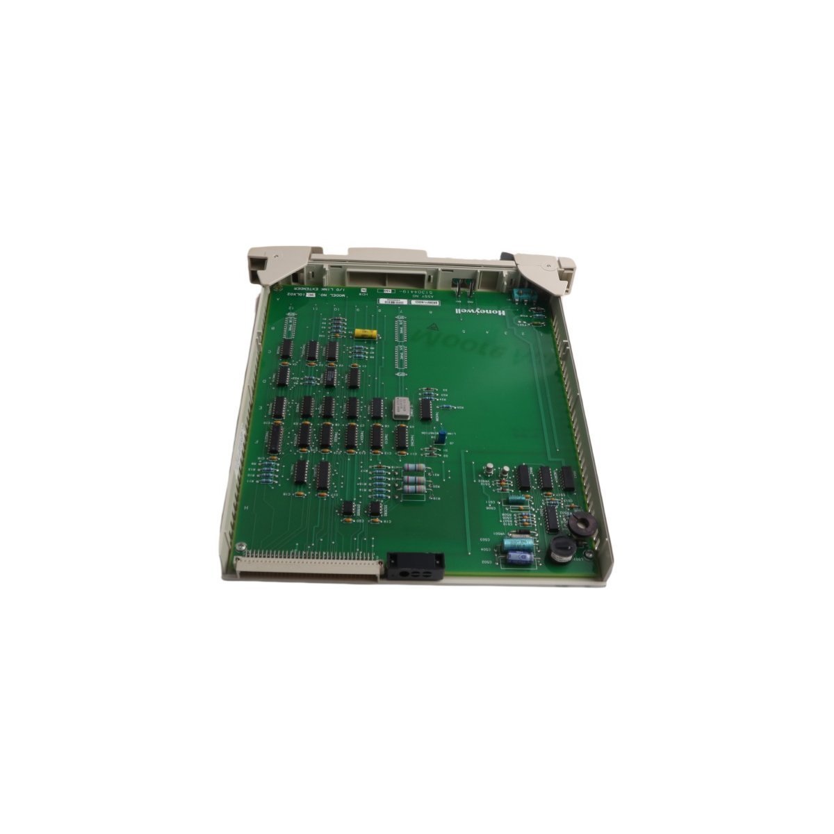
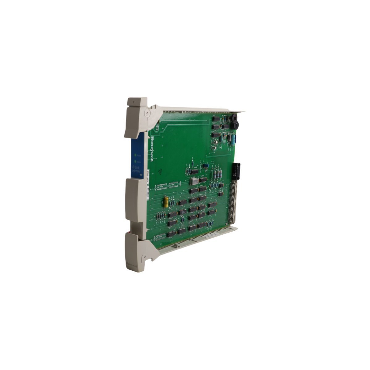
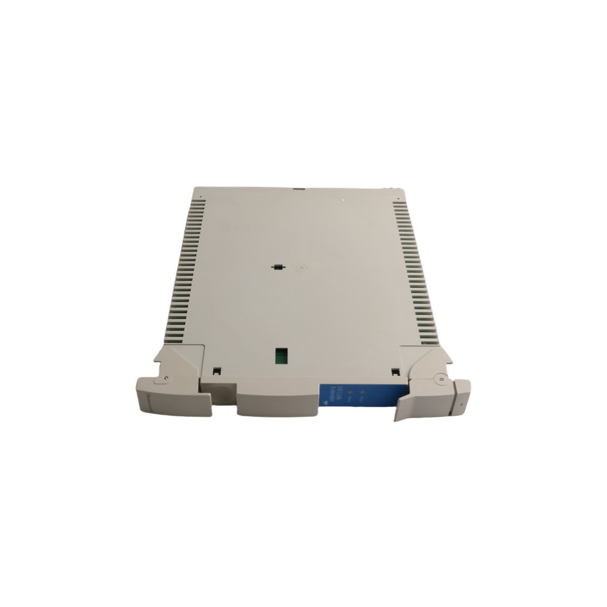
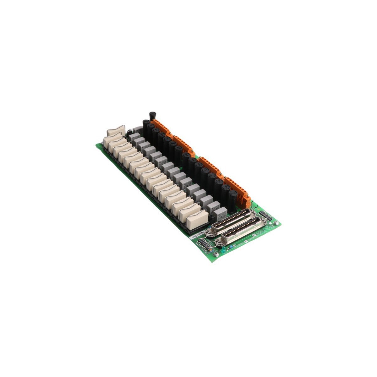
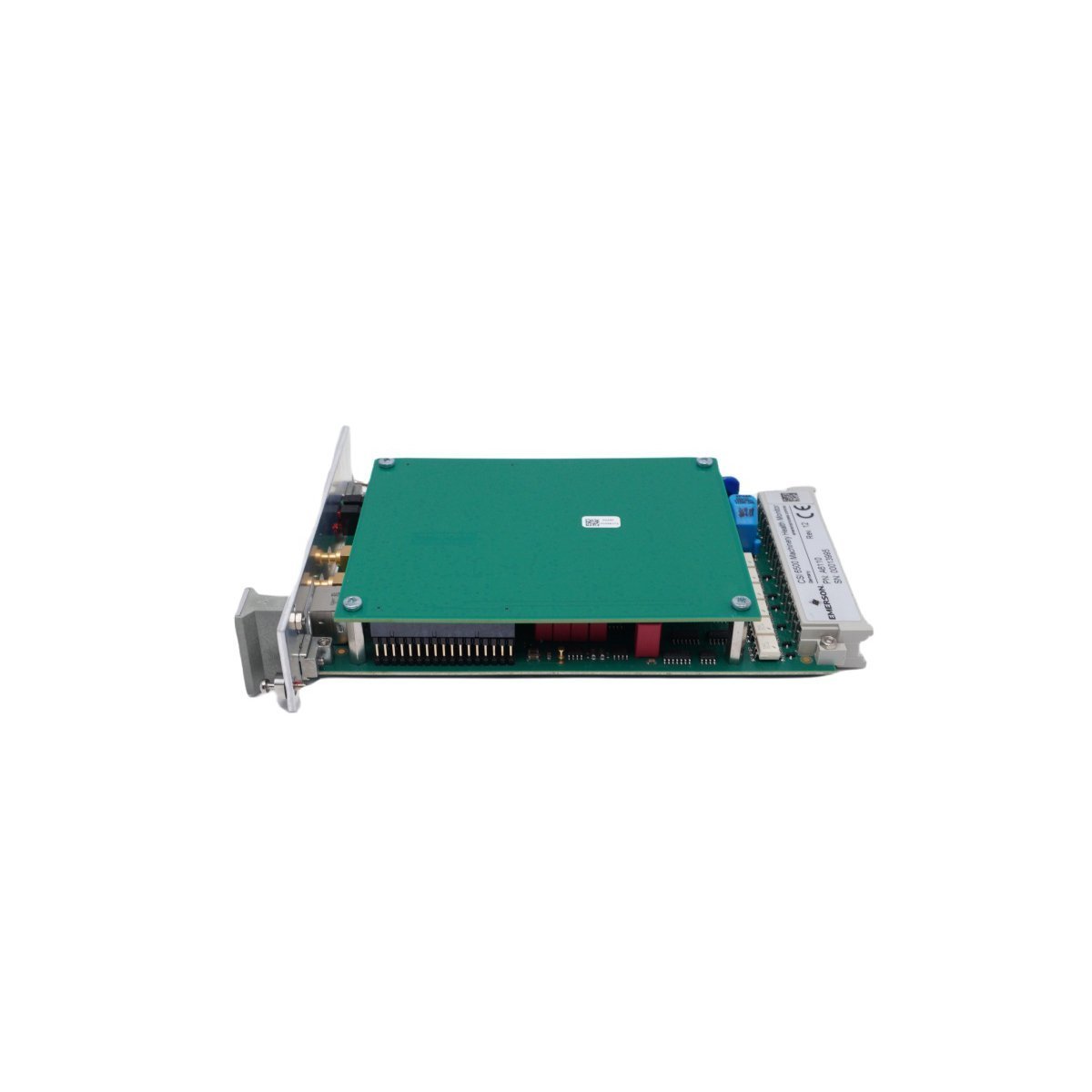
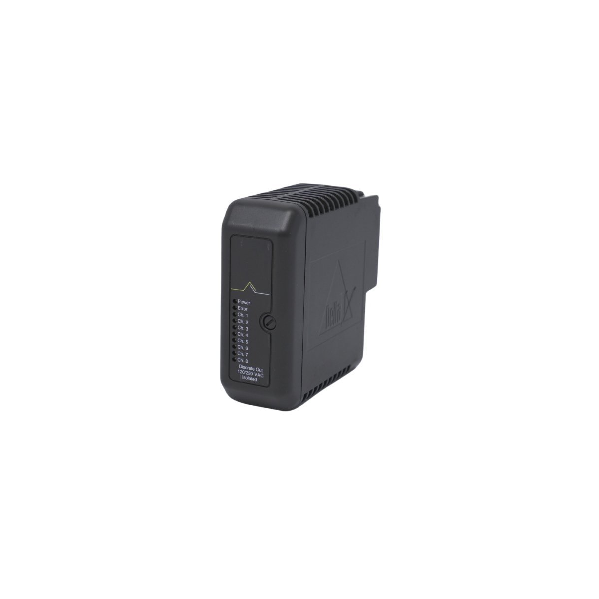
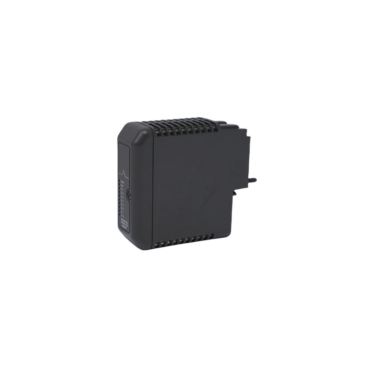
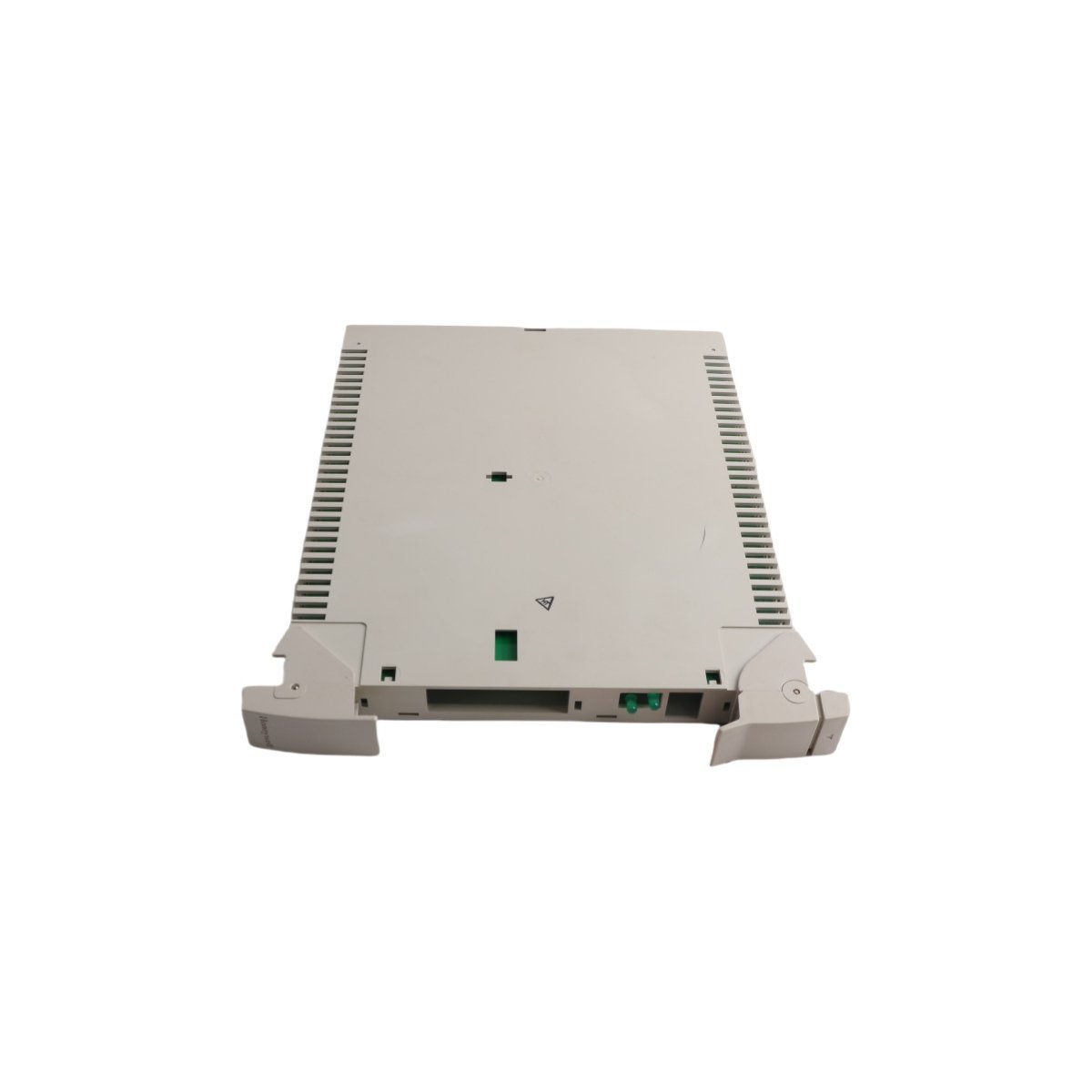
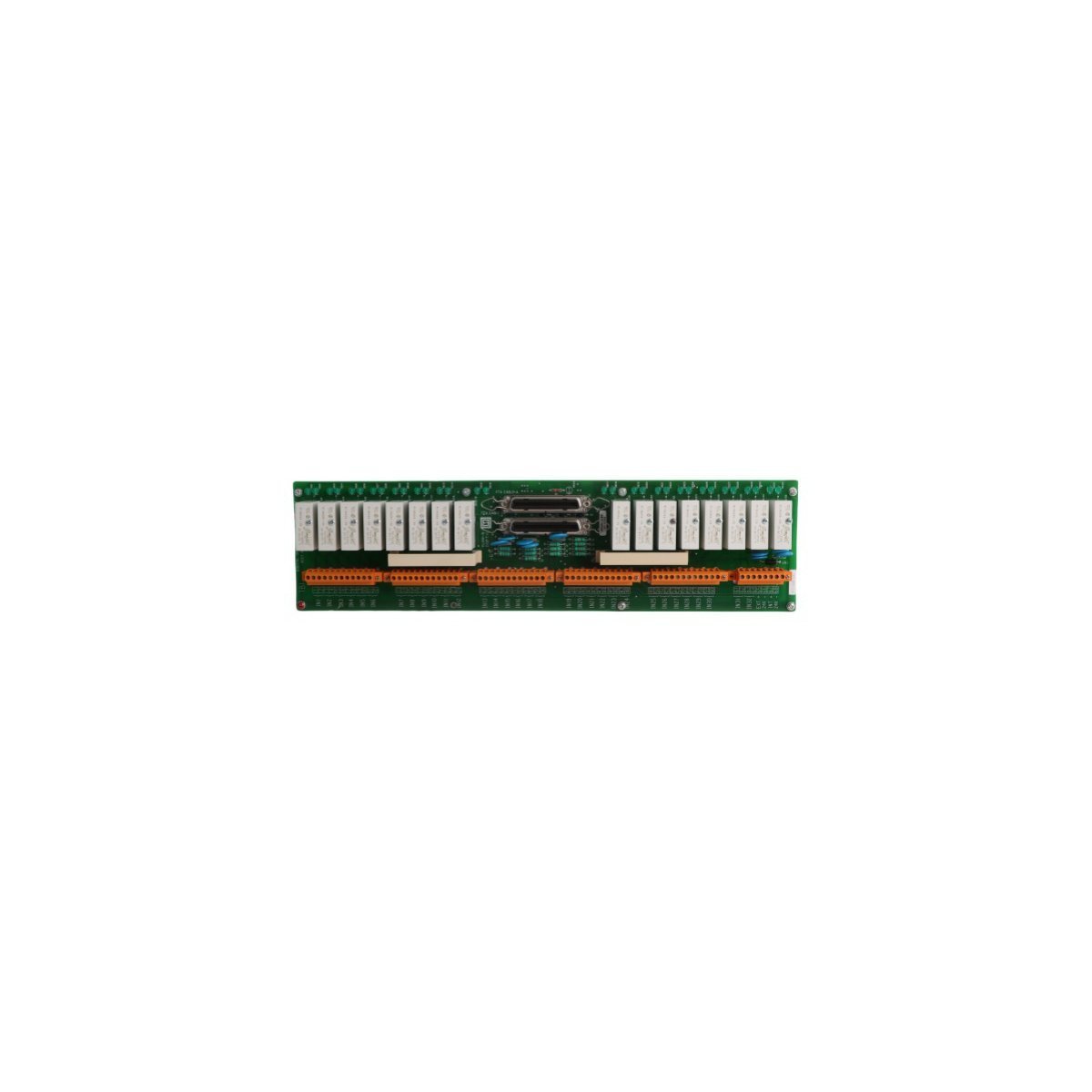
Honeywell MC-IOLX02 I/O Link Extender Card

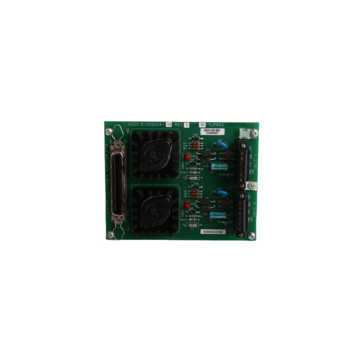
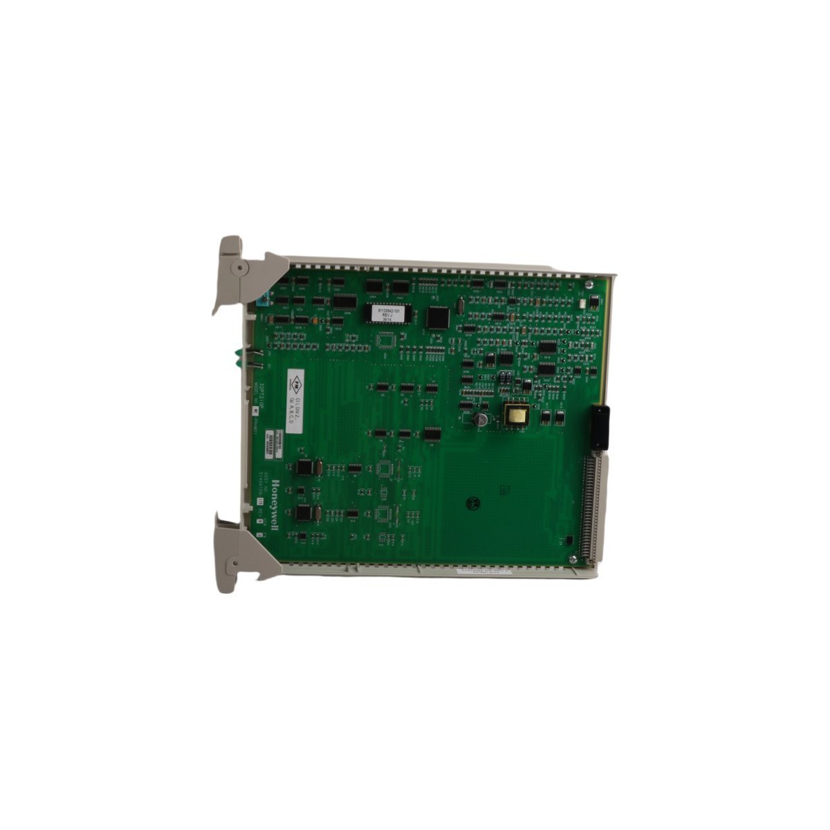
The Honeywell MC-IOLX02, also cataloged as the 51304419-150 I/O Link Extender Card, operates as a dedicated hardware component for signal expansion and physical layer coupling within distributed control system (DCS) architectures.

Hardware Specifications

ParameterSpecification
ModelMC-IOLX02
BrandHoneywell
OriginUSA
Weight0.58 kg
Dimensions3 x 31.8 x 27.8 cm
Operating TempIndustrial standard
Power ConsumptionSystem-bus dependent
Product RangeMU-T Series
Communication ServiceEthernet router

Process Control and DCS Connectivity

The Honeywell MC-IOLX02 facilitates signal integrity across DCS loops by managing communication pathways between field-level devices and higher-level processing nodes. The module integrates 4-20 mA HART loop protocol standards, allowing for seamless integration with legacy instrumentation and modern smart field devices. Channel-to-channel isolation is implemented to mitigate electromagnetic interference, ensuring that analog signals remain stable even under high-density wiring conditions. The architecture supports standard HART digital communication overlays, providing diagnostics and configuration data without disrupting the primary process control loop.

Frequently Asked Questions

Q: Does the MC-IOLX02 support hot-swap functionality within the MU-T Series rack?

A: Yes, the module is designed for insertion and extraction under power; however, control logic must be verified to ensure the I/O state transition does not trigger an unexpected process response.

Q: What is the primary function of the Ethernet router service integrated into this module?

A: The onboard communication service manages data packet routing between the I/O link and the system backplane to ensure deterministic timing for process variables.

Q: Are there specific shielding requirements for the input cabling connected to this card?

A: Yes, all signal cabling must utilize high-quality twisted-pair shielded cables with the shield grounded at the cabinet entry point to maintain signal-to-noise ratios.

Field Installation Guidelines

  • Initially, ensure the control cabinet power is isolated before inserting the module into the designated slot of the MU-T Series backplane.

  • Subsequently, verify that the mechanical guides are correctly aligned before applying the necessary force to seat the card connector.

  • Following this, secure the module using the provided captive screws to maintain vibration resistance and establish a low-impedance electrical contact with the backplane ground rail.

  • Simultaneously, route all field wiring separately from high-voltage AC power lines to prevent induced noise on the I/O channels.

  • Finally, perform a point-to-point wiring continuity check to confirm circuit integrity before initiating system-level loop configuration.