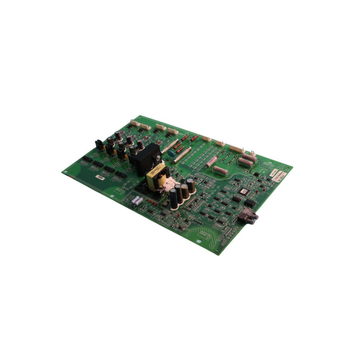
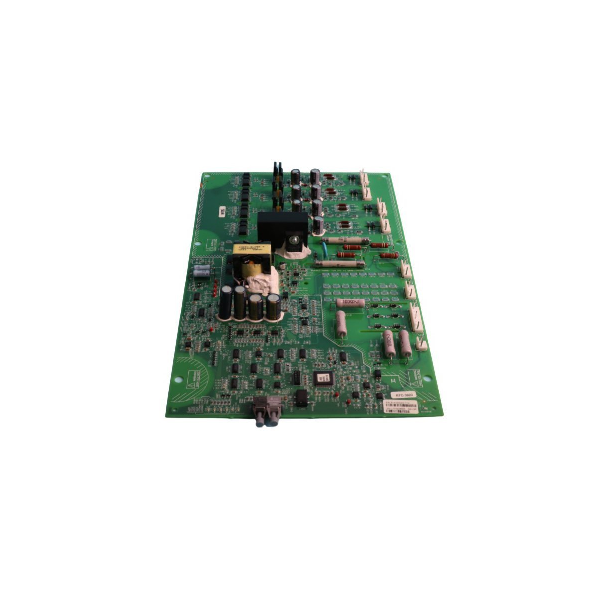
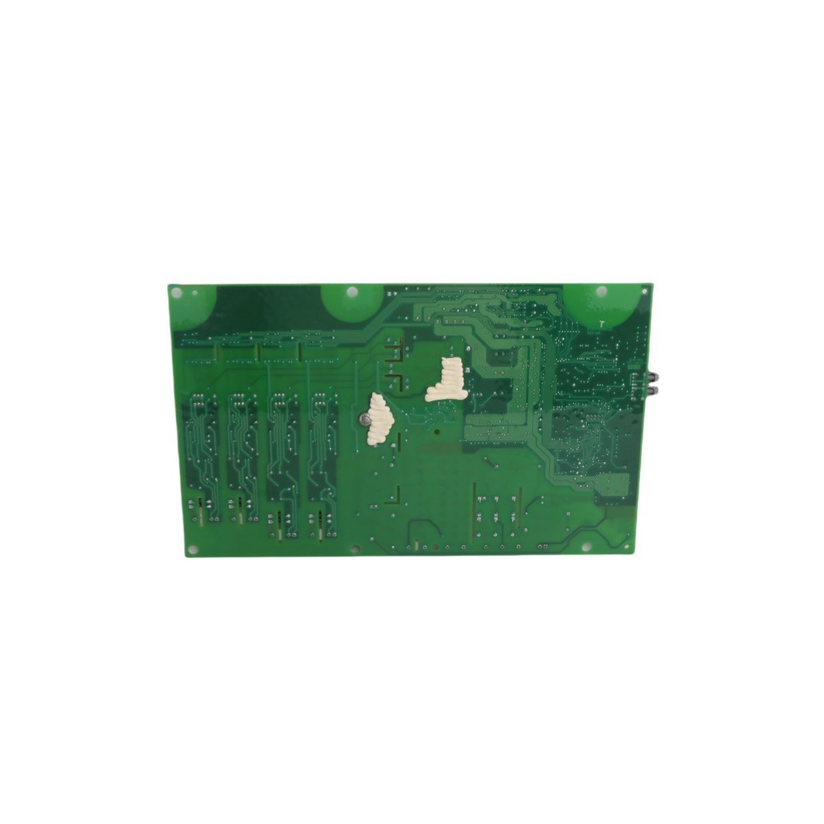
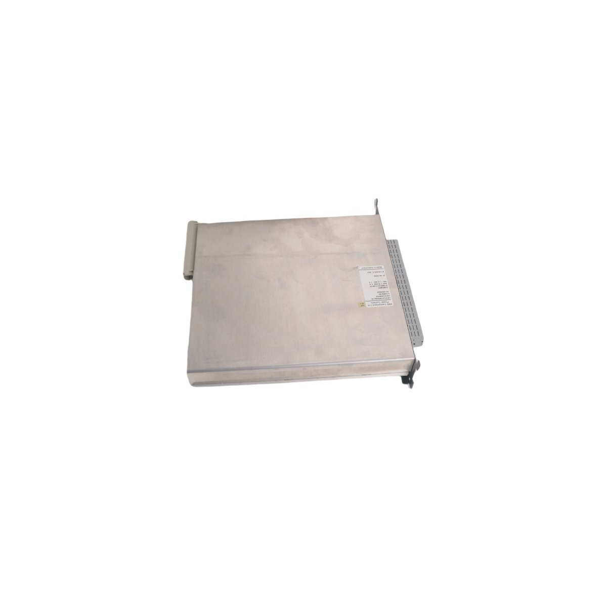
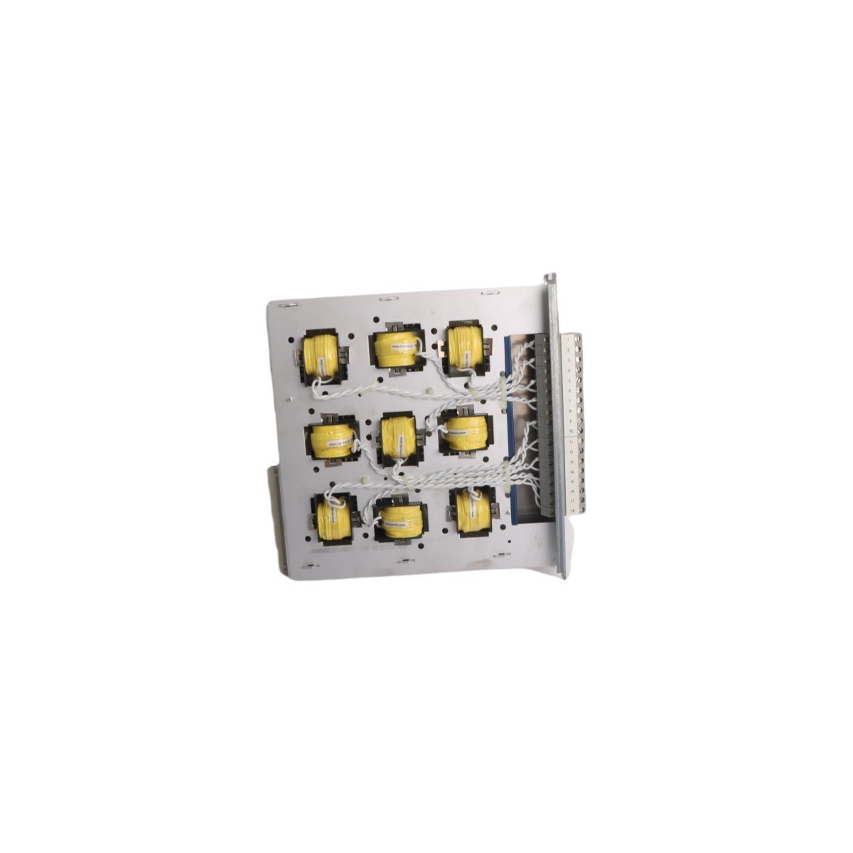
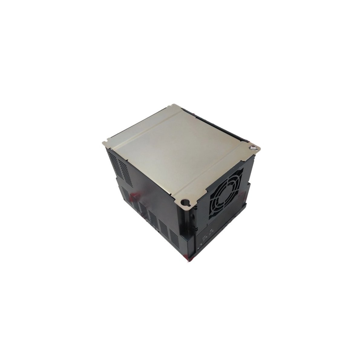
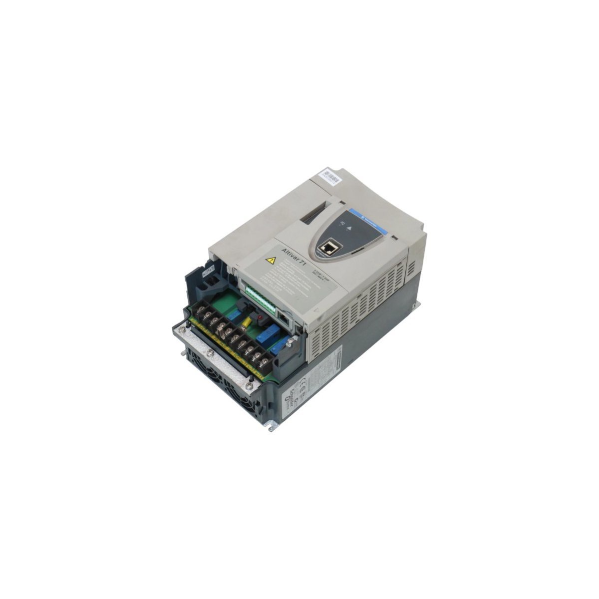
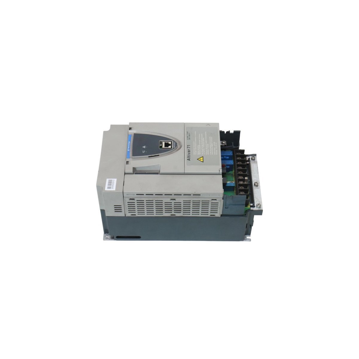
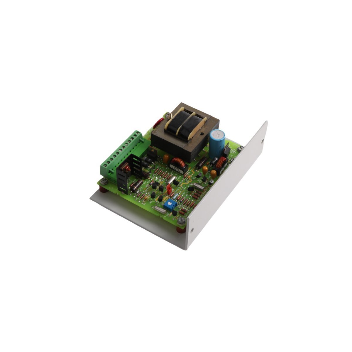
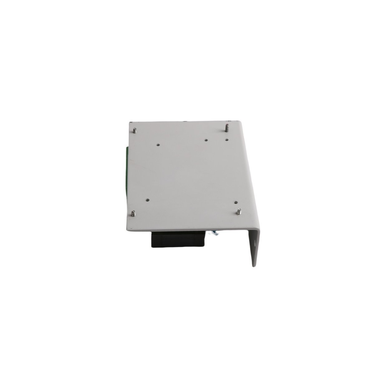
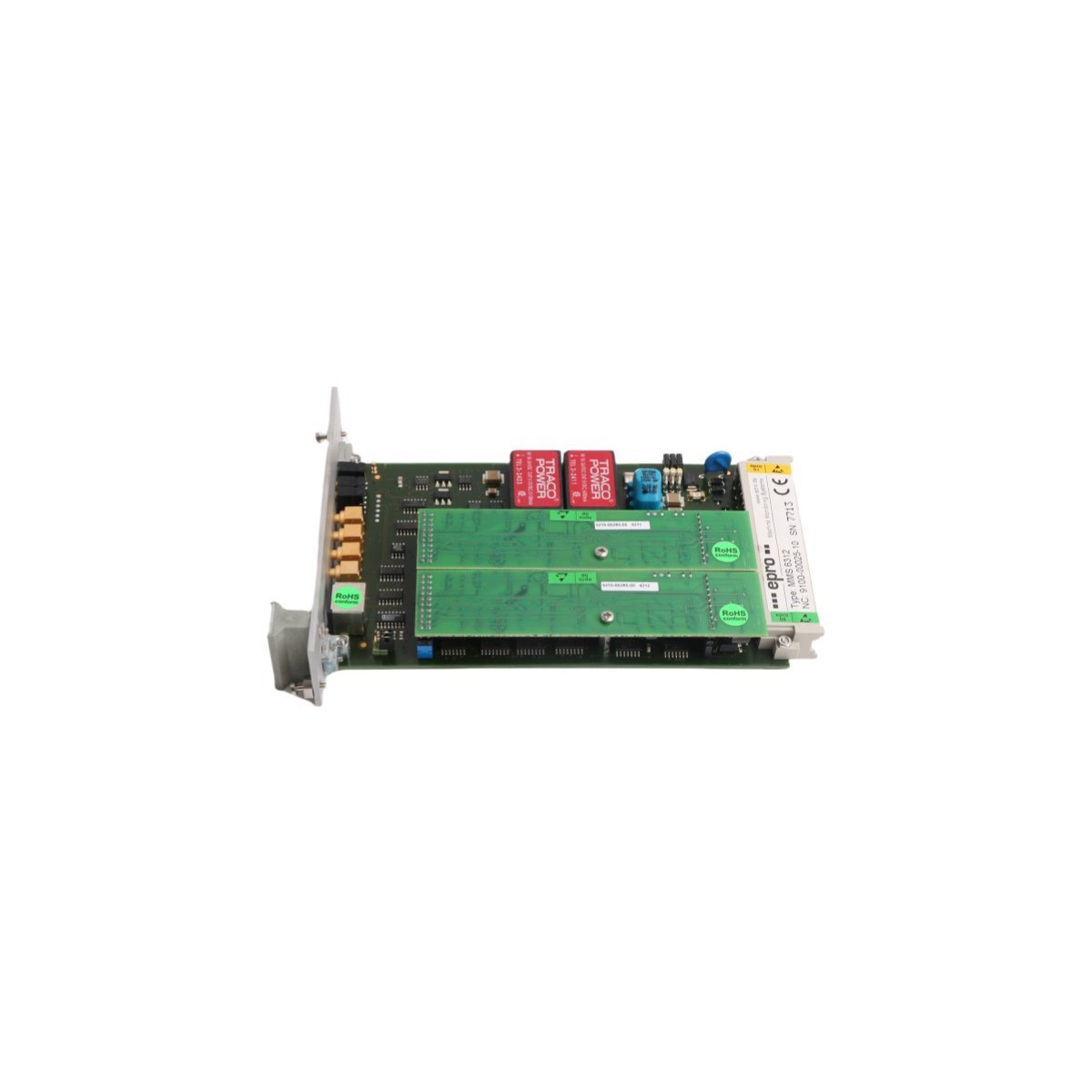
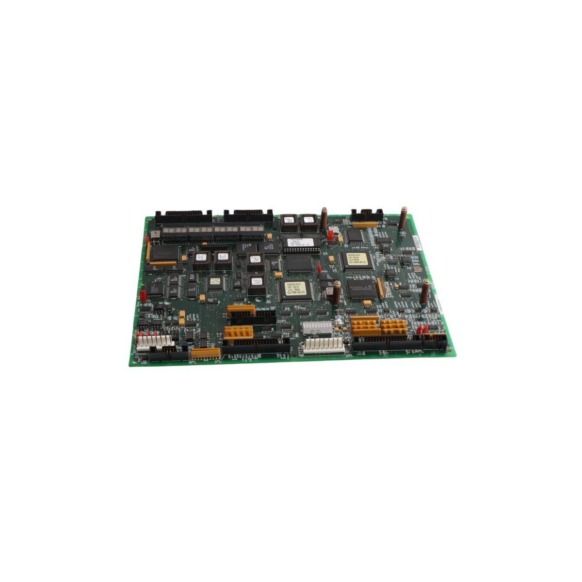
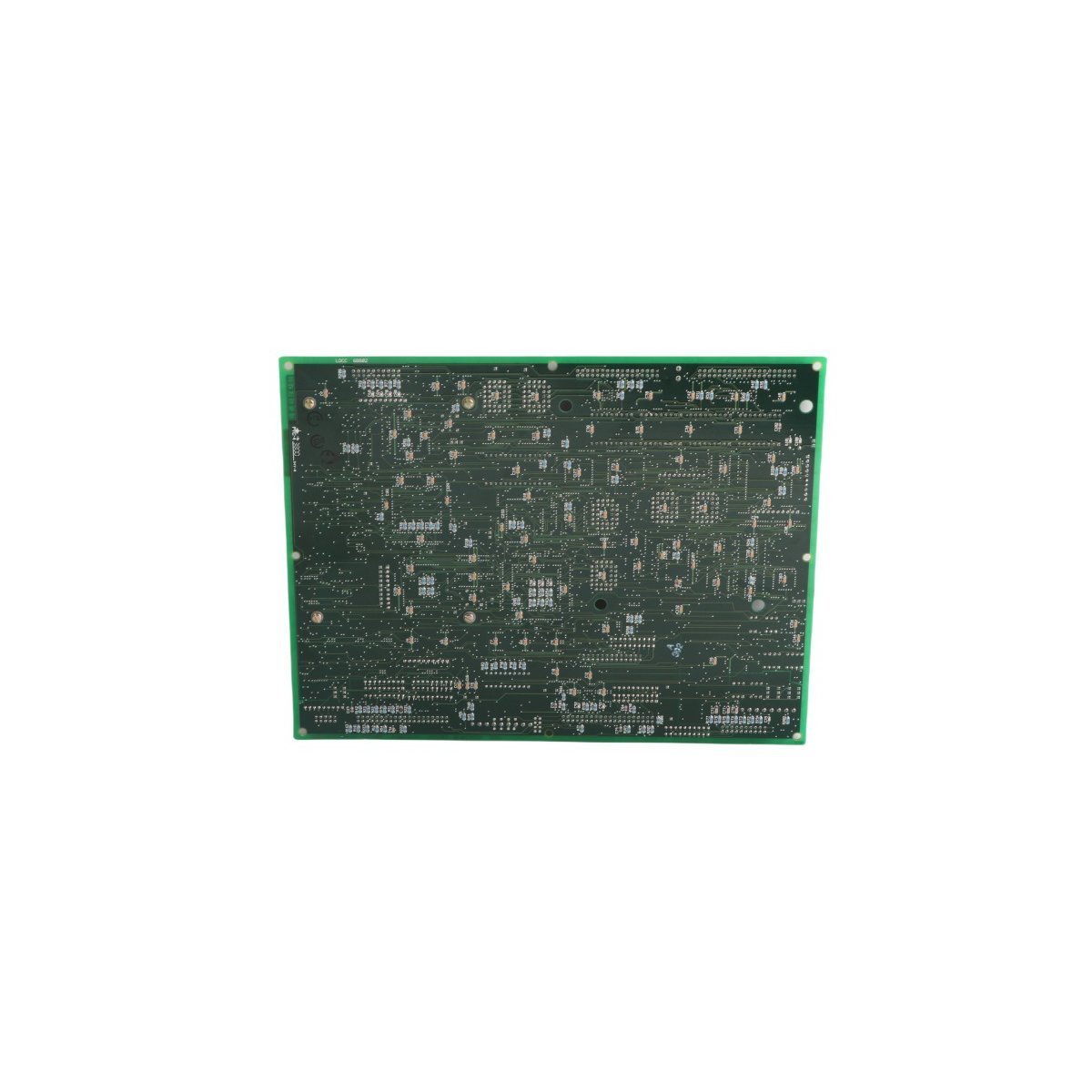
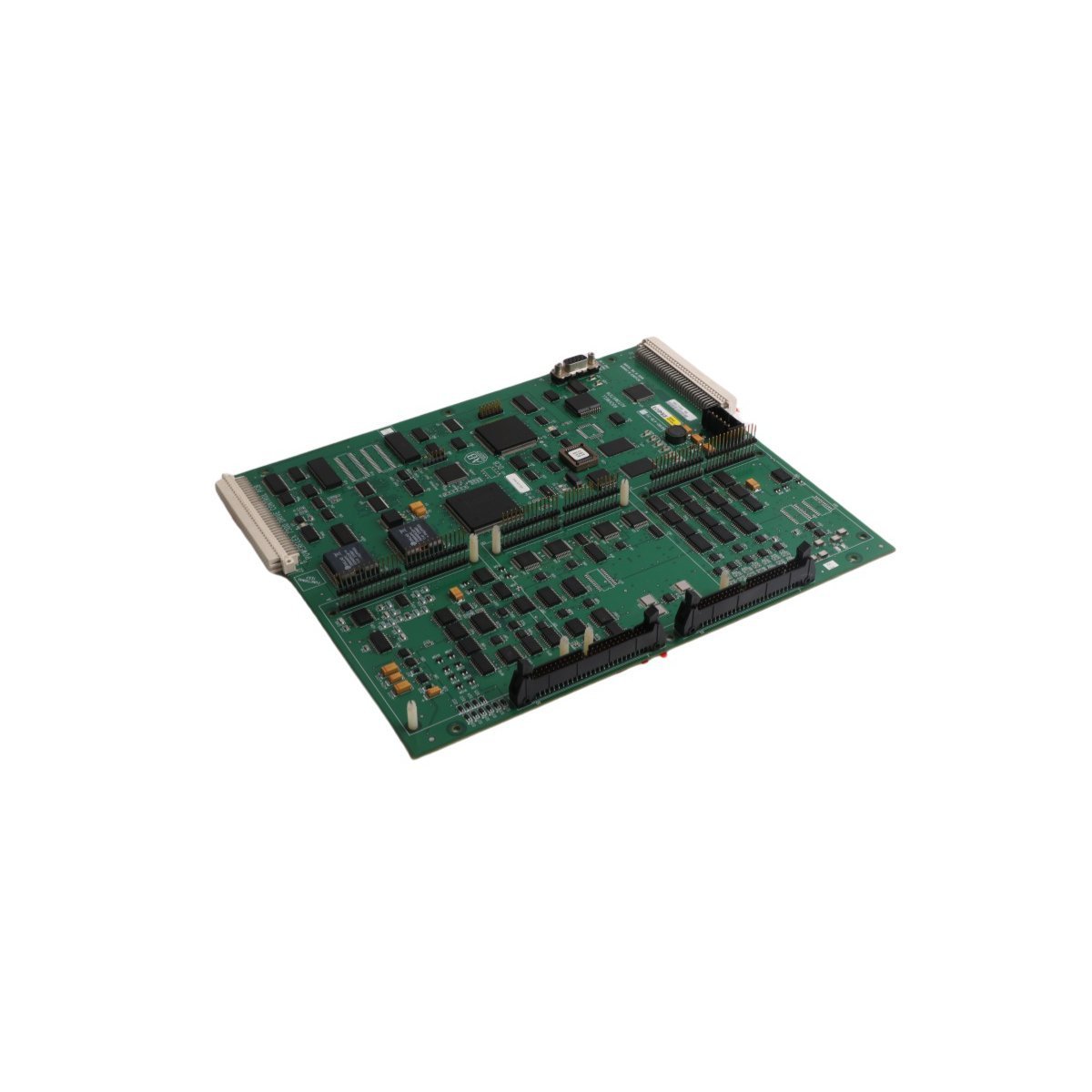
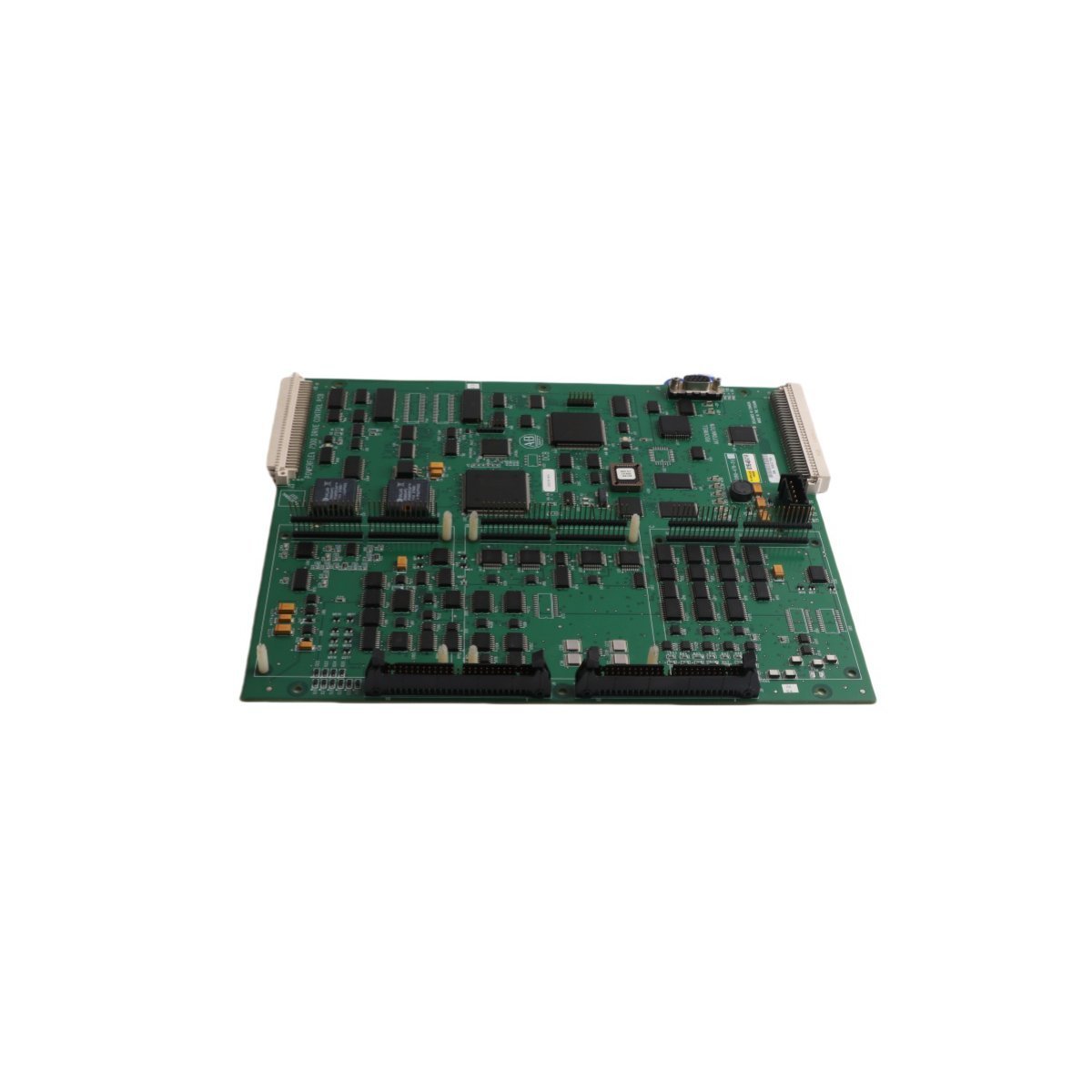
Configured for power management in medium-voltage drive platforms, the Siemens A1A10000432.71M (A1A10000432.71M Control Board) provides direct physical and electrical execution for motor control sequences.
Hardware Specifications
Parameter
Specification
Model
A1A10000432.71M
Brand
Siemens
Origin
GERMANY
Weight
0.48 kg
Dimensions
2 cm x 25.5 cm x 26.2 cm
Operating Temp
-20 deg C to +60 deg C
Power Consumption
Input 24 VDC; Current ≤ 10 A
Isolation
2500 VAC (IEC 61800-5-1)
PLC and Drive Control Integration
The A1A10000432.71M utilizes deterministic backplane bus communication to synchronize drive firing angles and control loops. The board enables precise I/O density scaling within the Robicon drive rack, facilitating high-speed feedback processing for current and voltage regulation. Firmware compatibility is verified via the primary controller interface, ensuring the board supports real-time execution of motor control algorithms without latency. It incorporates hardware-level overvoltage and undervoltage protection, calibrated for integration within deterministic Profinet or EtherNet/IP networks.
Frequently Asked Questions
Q: Can this board be replaced while the medium-voltage drive is energized?
A: No. The A1A10000432.71M does not support hot-swapping. All input power and DC bus supplies must be isolated and verified at 0 V before module extraction to avoid damage to the backplane connectors.
Q: How should firmware compatibility be verified?
A: Compatibility must be confirmed by matching the board’s revision index with the central control processor’s firmware version to ensure the deterministic timing of the control algorithms remains synchronized.
Field Installation Guidelines
Initially, verify that the control rack is de-energized to prevent electrical faults during the insertion process.
Subsequently, inspect the backplane slots for any mechanical obstructions or debris that could impede the seating of the board connectors.
Following this inspection, align the A1A10000432.71M carefully with the internal card guides, ensuring the unit is perpendicular to the backplane to prevent pin deformation.
Once aligned, apply firm pressure until the unit is fully seated and tighten all mechanical retention fasteners to establish a secure ground connection with the chassis.
Finally, ensure that all signal wiring is routed using dedicated, shielded cable pathways to minimize the potential for electromagnetic interference from power-stage switching transients.
The ABB HESG216850M1/D (316GW61) is a high-performance Procontic b Control Board. It features a 1MHz processor, 1MB memory, and 64 total I/O channels. Designed for harsh environments, this IP65-rated module supports MODBUS and CANopen for seamless DCS integration.
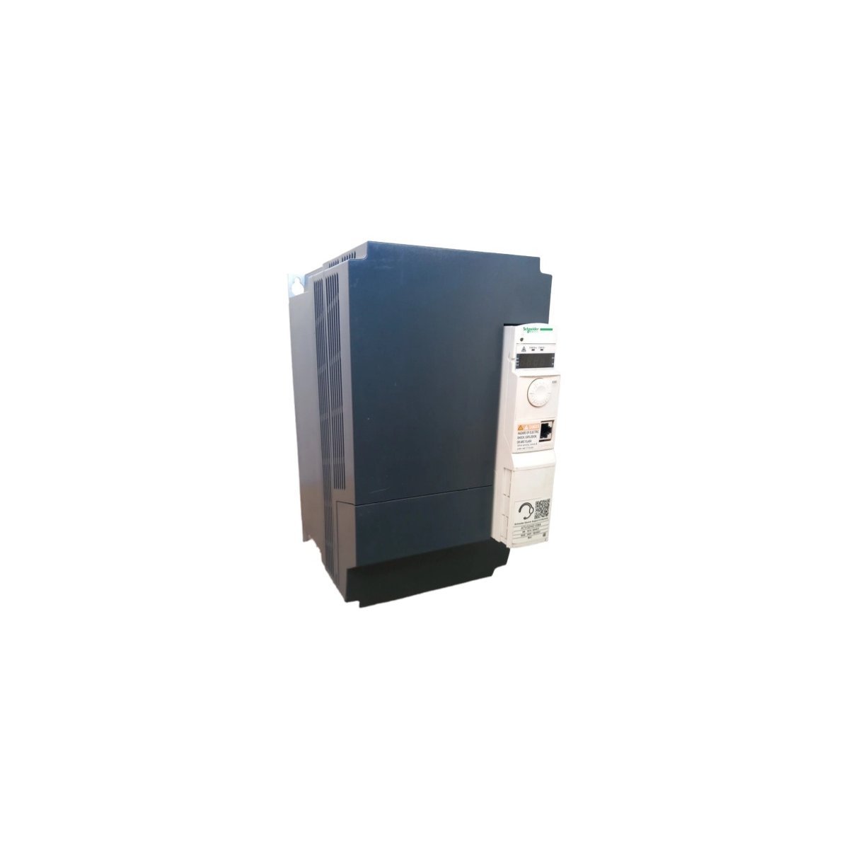
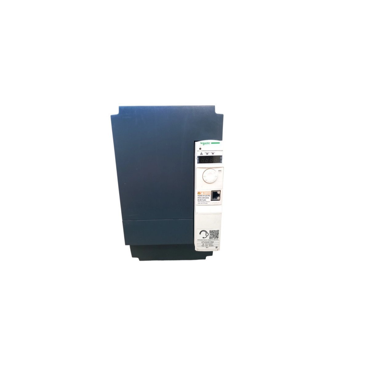
The Schneider Electric ATV32HD15N4 is a 15kW Altivar 32 variable speed drive designed for 380-500V three-phase motors.It features a compact book-style design, integrated safety functions, and advanced vector control for high-performance industrial automation and machinery
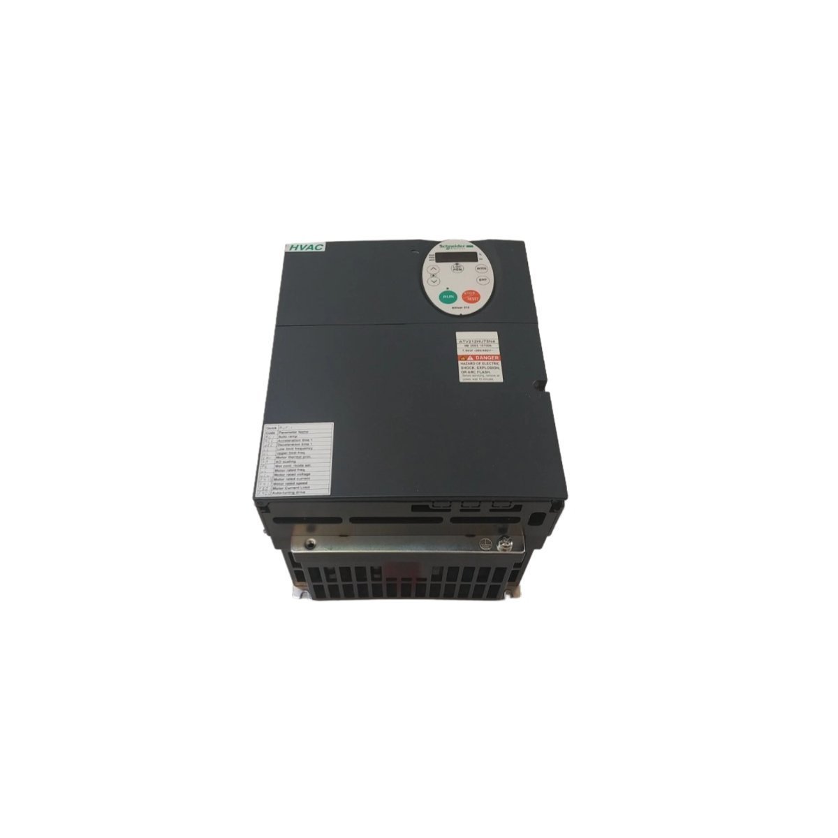
The Schneider Electric ATV212HU75N4 is a 7.5kW (10HP) Altivar 212 variable speed drive designed for HVAC fans and pumps. It features 380-480V three-phase input, native BACnet/Modbus support, and IP21 protection for high-efficiency building management applications.
The Schneider Electric ATV71HU55N4 is a 5.5kW (7.5HP) Altivar 71 variable speed drive designed for 380-480V three-phase motors.Built for high-torque applications, it features advanced flux vector control, integrated EMC filters, and a graphic terminal for precision industrial automation.
The Allen-Bradley 80190-580-01-R is a high-performance Drive Processor Module and Analog Control Board.Designed for industrial motor management, it features a 14-pin header and four on-board connectors to provide precise control and high-speed data processing for complex drive systems.
The Schneider Electric ATV71HC25N4 is a premium Altivar 71 variable speed drive engineered for high-torque industrial applications. It supports 380-480V three-phase motors, offering precision speed regulation, advanced energy optimization, and robust protection for heavy-duty process machinery and hoisting systems.
The GE 531X207LCSAMG1 is a LAN current source card designed for the 531X drive and exciter series.It converts 115 VAC input into regulated 5 VDC and 15 VDC outputs to power network communication boards, featuring an adjustable potentiometer and jumper-selectable settings for precise industrial control.
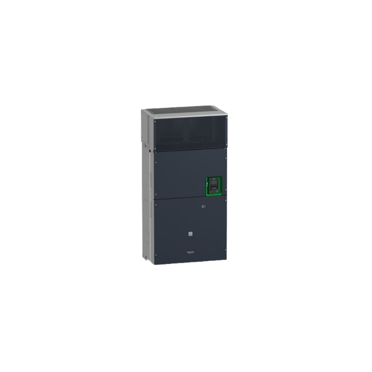
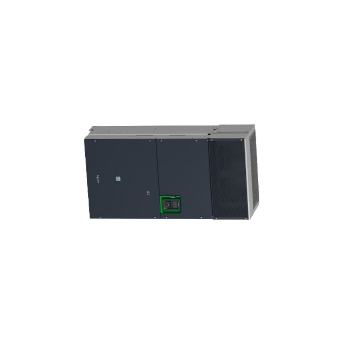
The Schneider Electric ATV930C25N4C is a high-power 250kW (400HP) Variable Speed Drive from the Altivar Process 900 series.Featuring advanced IIoT connectivity, master/slave coordination, and dual-rating overload support, it is designed for demanding 380-480V industrial applications.
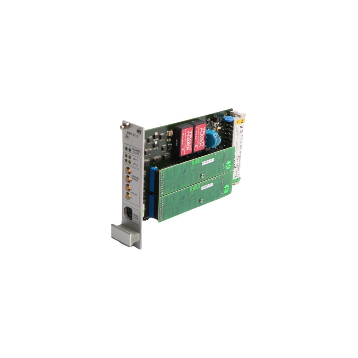
The Emerson MMS6312 is a professional dual-channel rotational speed monitoring module designed for the MMS6000 system. It provides high-precision speed measurement, direction detection, and overspeed protection for critical rotating assets, ensuring maximum safety in power and process industries.
The GE DS200LDCCH1ALA is a high-performance Drive Control and LAN Communications Board designed for the Mark V Speedtronic system. Featuring four dedicated microprocessors (DCP, MCP, LCP, CMP), it provides advanced motor control and multi-protocol bus support for DIRECTO-MATIC 2000 industrial drives.
The Allen-Bradley 20AD1P1A3AYNNNC0 is a 480V, 0.5 HP PowerFlex 70 AC Drive designed for precision motor control.Featuring an IP20 panel-mount enclosure, integrated Safe Off functionality, and an internal EMC filter, it offers a compact and safe solution for small-scale industrial automation and machinery.
The Allen-Bradley 80190-480-01-R is a PowerFlex drive control board featuring 32 digital I/O points and 480V AC compatibility. Providing 7.2kW power handling and multi-motor support, this USA-made module ensures precise and reliable motor regulation for complex industrial automation.
We are committed to protecting your privacy. The information collected here is strictly used to provide the requested quotes, technical support, and relevant industrial automation solutions.