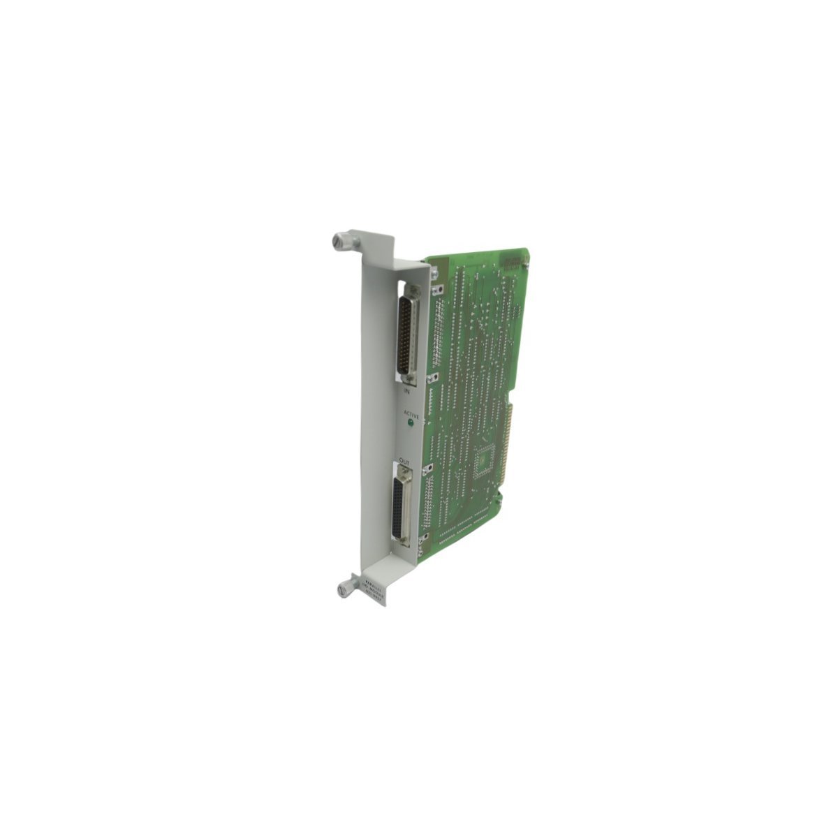
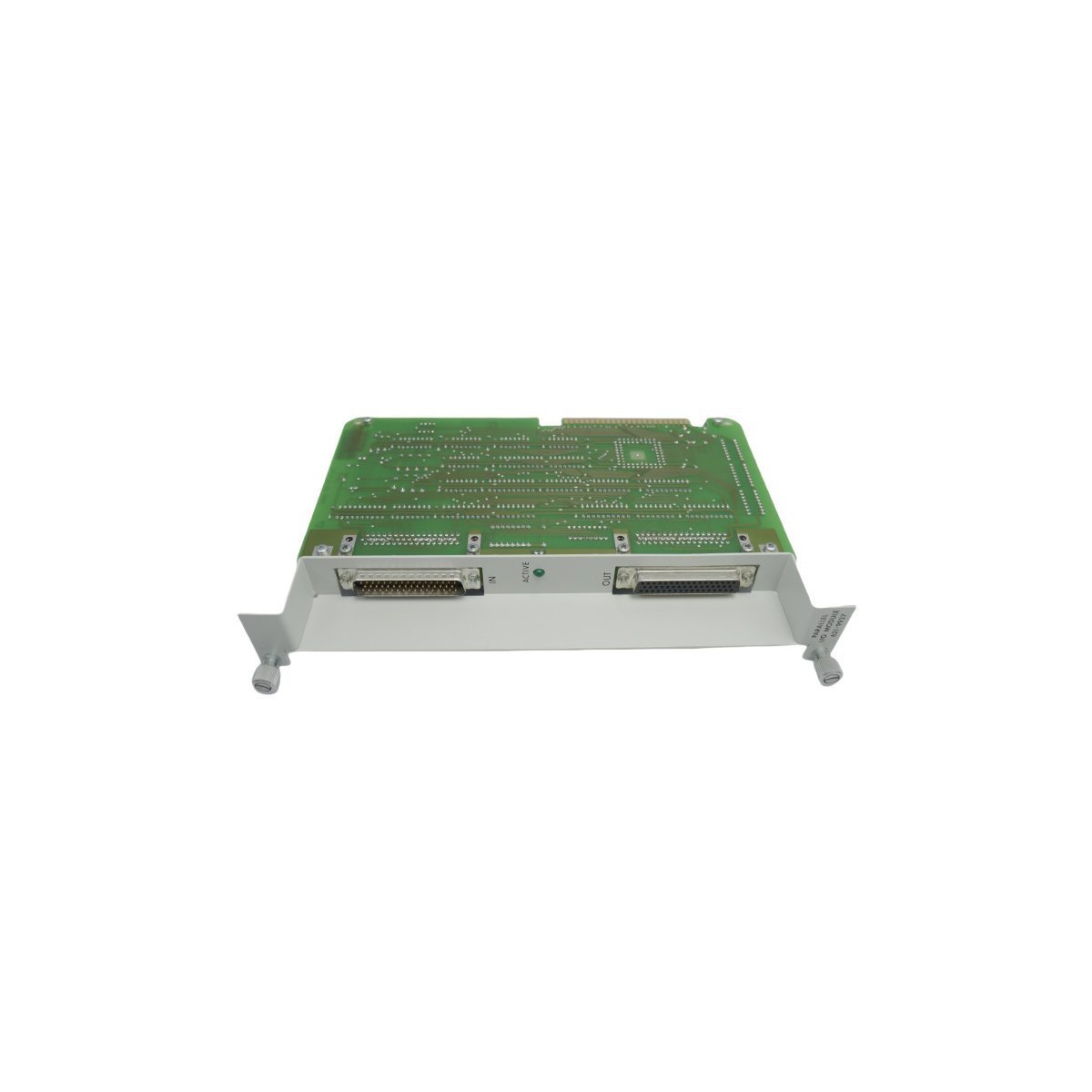
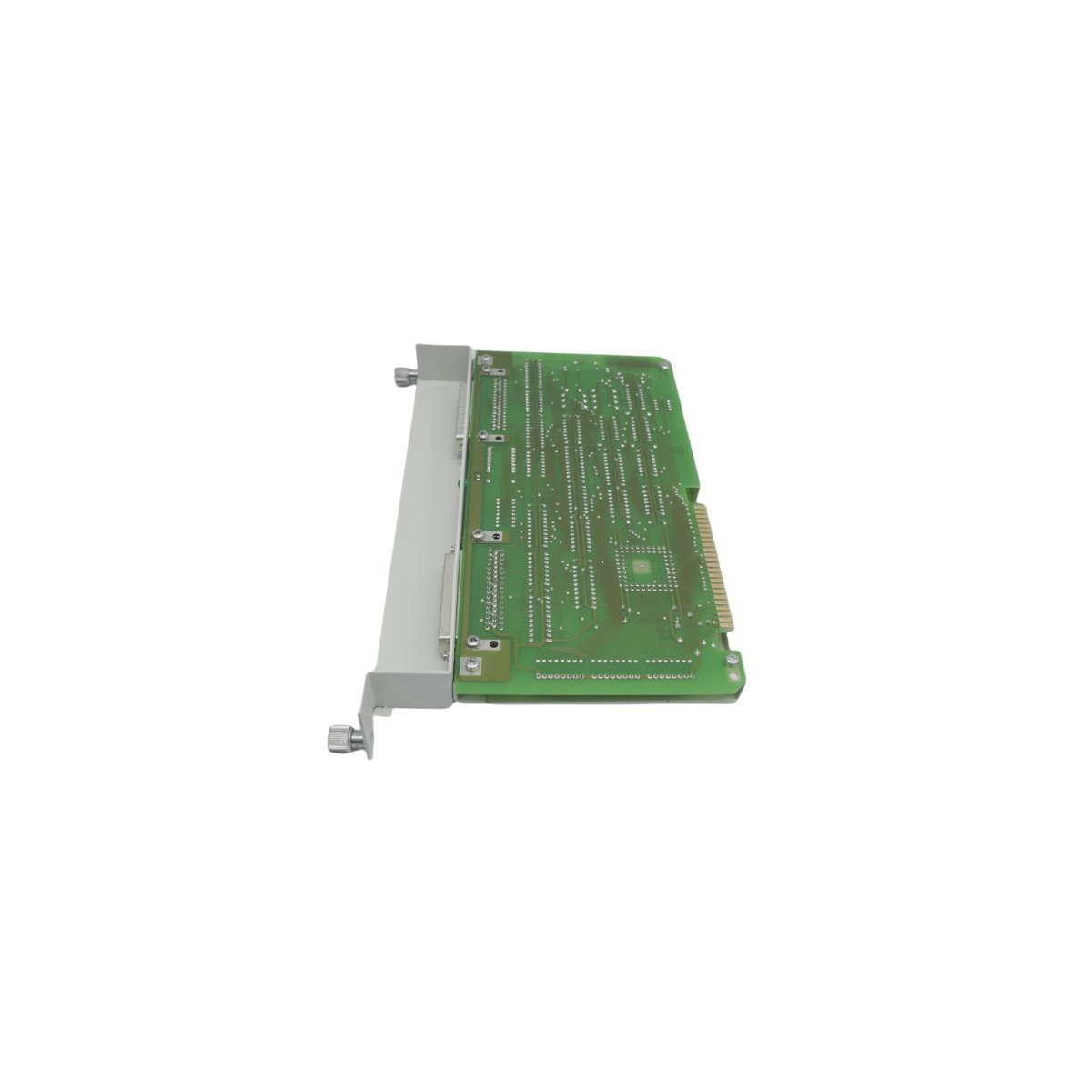
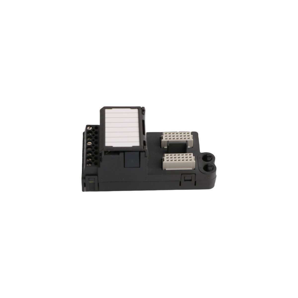
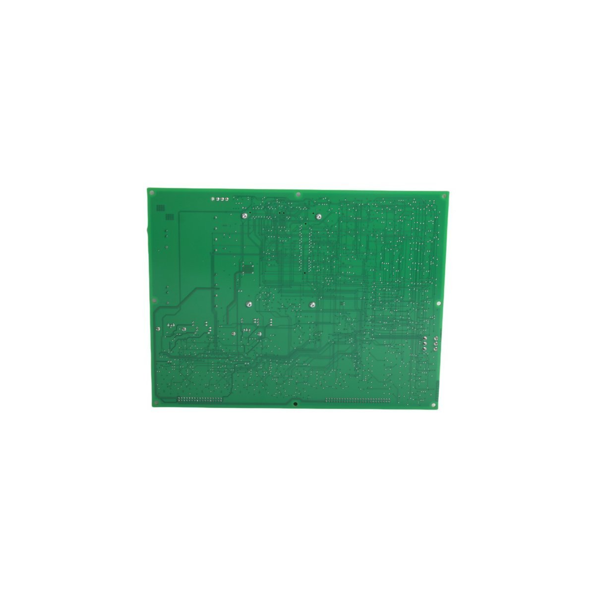
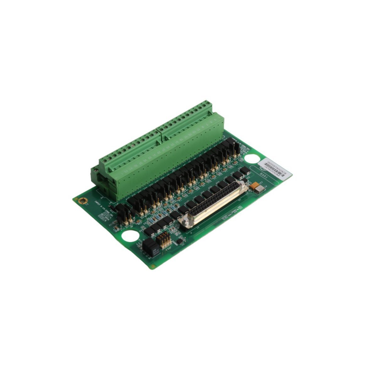
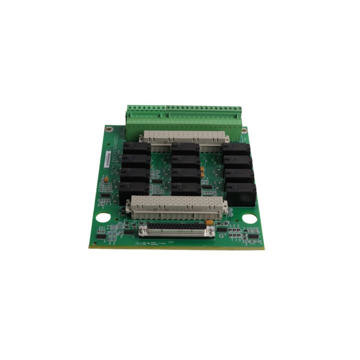
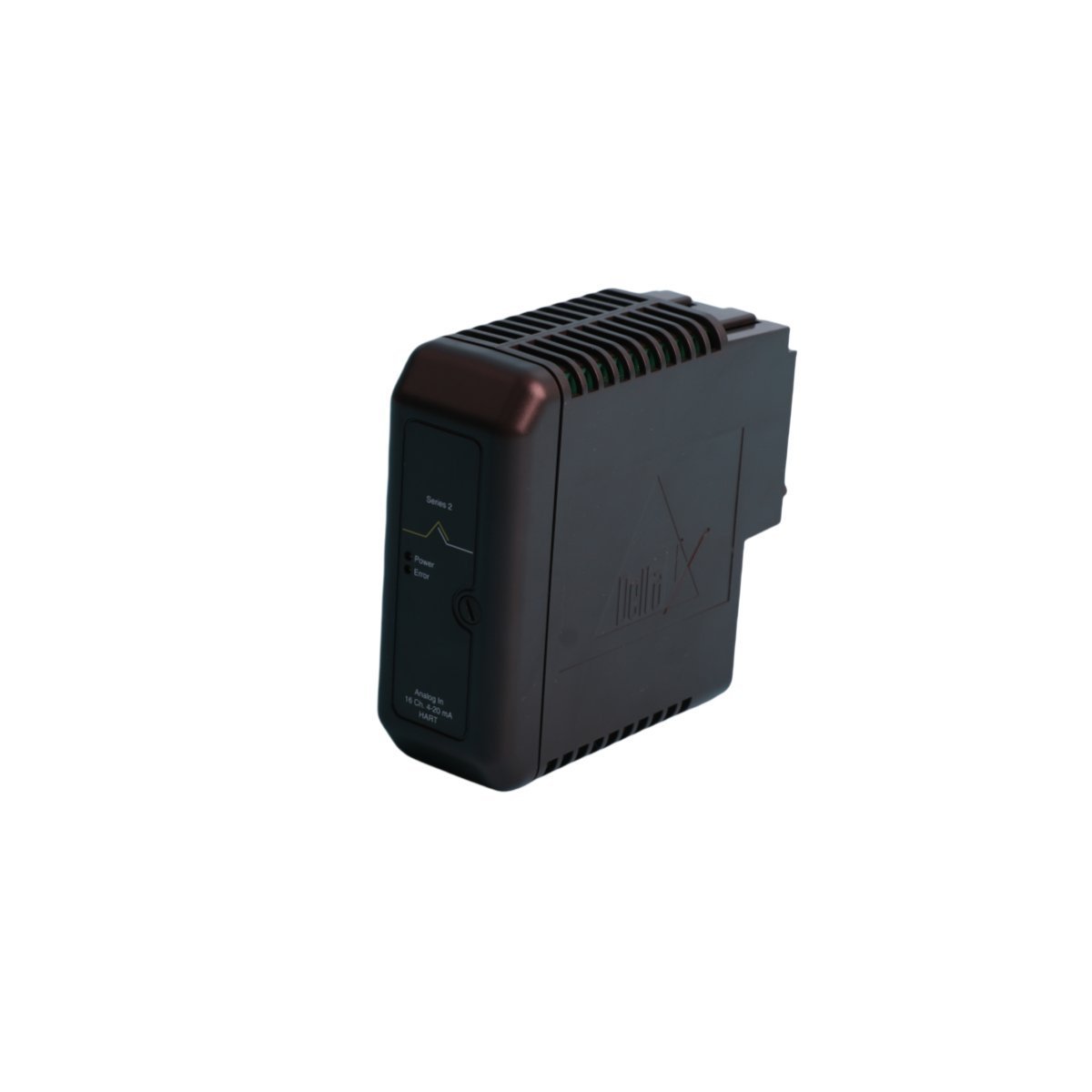
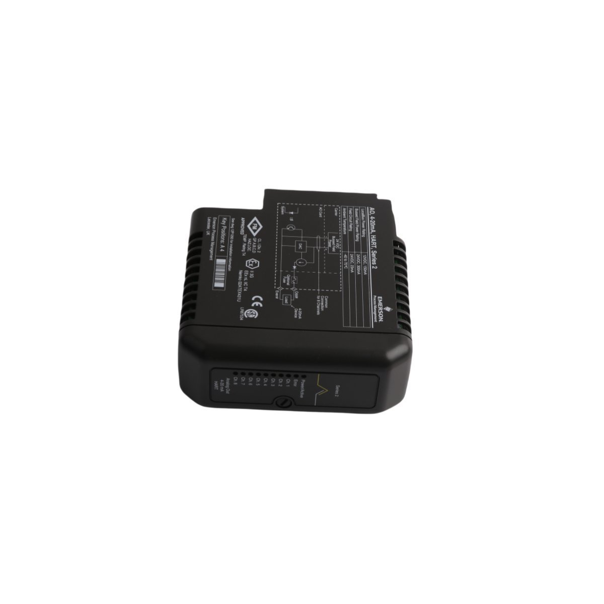
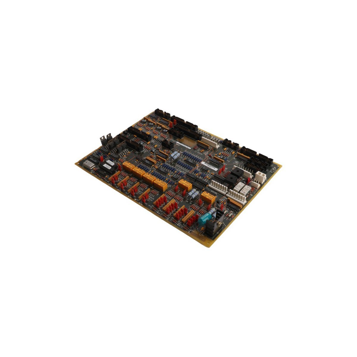
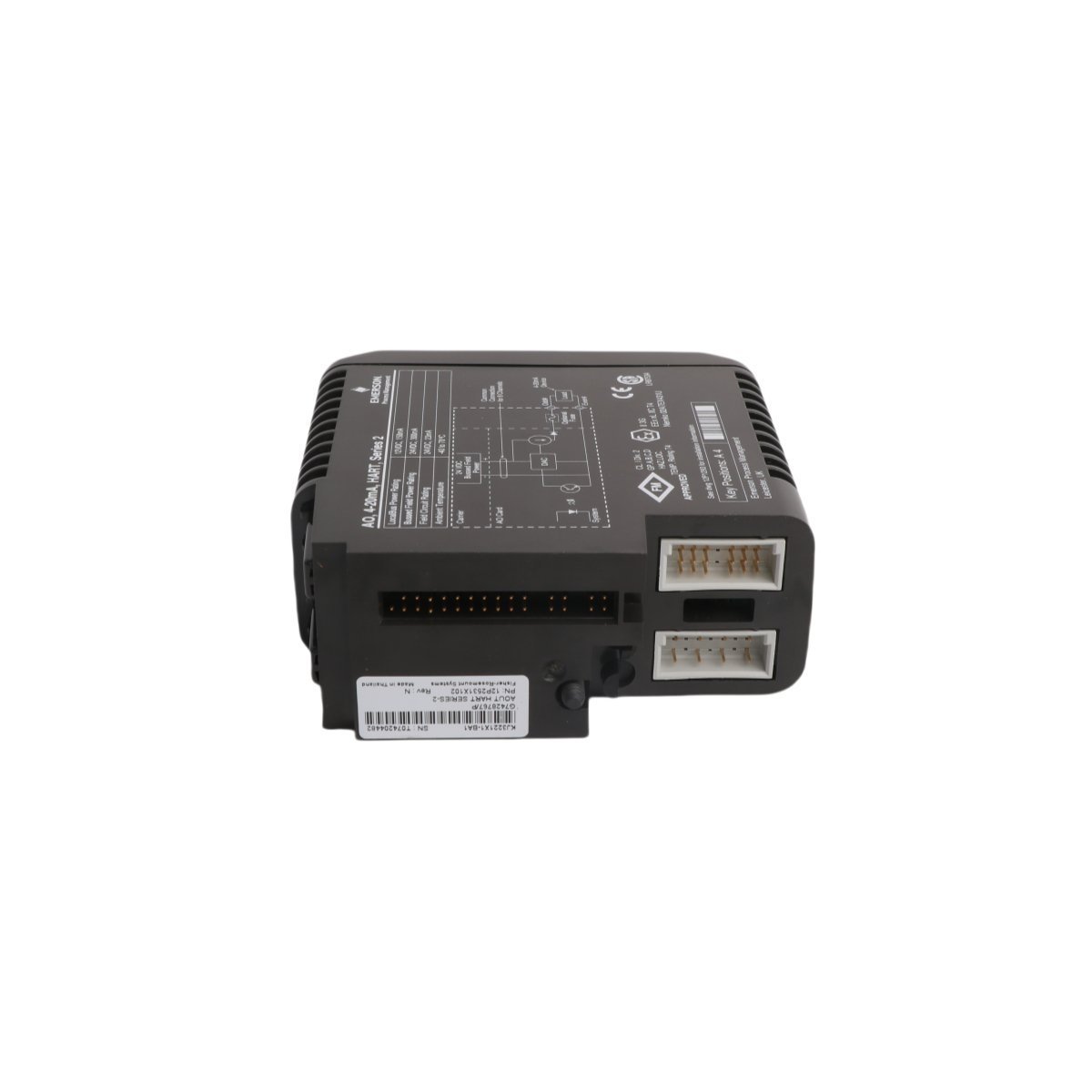
provide original Honeywell 621-9940C Serial I/O Module from IPC 620 range. Brand New, Original Stock, Global Shipping. Technical manual parameters listed.
The Honeywell 621-9940C, also cataloged as the 621-9940C Serial I/O Module, serves as the primary 621-9940C Serial I/O Module utilized to execute real-time data exchange across IPC 620 platforms. The hardware functions as an interface interface node within legacy DCS configurations, converting specific protocol streams to execute synchronous data processing without introducing loop propagation delays.
Hardware Specifications
Parameter
Specification
Model
621-9940C
Brand
Honeywell
Origin
USA
Weight
0.7 kg
Dimensions
3.2 cm x 26.5 cm x 17.1 cm
Operating Temp
0 to +60 deg C
Power Consumption
Backplane drawn via rack chassis configuration
Module Type
Serial I/O Module
System
IPC 620 / DCS
Communication Service
Serial to backplane conversion
Process Control & Channel-to-Channel Isolation
The Honeywell 621-9940C relies on a dedicated layout to route internal serial communication data lines over the IPC 620 rack framework. It incorporates localized channel-to-channel isolation networks that protect the inner processing registers against field loop transients. Standard operations maintain clean data throughput by utilizing continuous error-checking structures, filtering out induced electrical noise on long-distance 4-20 mA HART loop protocol lines or parallel industrial serial interfaces.
Frequently Asked Questions
Q: Does this module support direct hot-swap insertion within an active IPC 620 rack?
A: No. Standard IPC 620 backplane architectures require complete rack de-energization before extracting or inserting I/O hardware to prevent data corruption on the active bus structure.
Q: What specific serial physical layers does the module interface with?
A: The hardware provides physical termination points for differential serial link configurations, routing standard telemetry data back to the central logic processing array.
Q: How is the address configuration determined for this I/O module?
A: Module addressing is established via physical DIP switch matrices situated on the side or rear of the printed circuit board assembly prior to slot insertion.
Field Installation Guidelines
Static Protection Measures: Handle the card assembly exclusively by the plastic faceplate or outer edges while utilizing an ESD-grounded wrist strap.
Slot Alignment Mechanics: Verify the orientation of the chassis card rails. Slide the unit smoothly inward until the rear pins match the female backplane receiver, then apply balanced pressure to finalize connection seating.
Shield Grounding Matrix: Terminate the external serial communication line shields directly to the chassis ground rail. Do not loop ground connections to avoid generating field measuring errors.
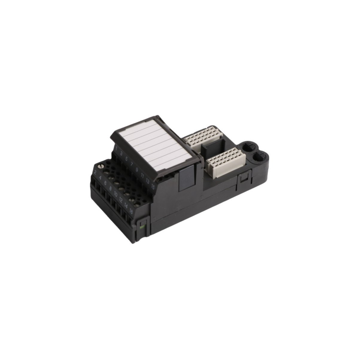
Configured for signal distribution in DeltaV M-series I/O Subsystem networks, the Emerson KJ4001X1-CA1 12P0623X072 (KJ4001X1-CA1 4-Wire Terminal Block) provides direct physical/electrical execution.
The KJ4001X1-CA1 functions as a passive interconnect interface within the DeltaV DCS architecture and facilitates direct field-to-I/O card connectivity. This terminal block secures 4-wire field signal connections and ensures consistent electrical continuity for both analog and discrete signal loops. Field engineers must follow DeltaV backplane wiring standards to maintain signal integrity and prevent impedance mismatches throughout the control loop. The design accommodates high-density terminal mounting and provides a structured physical path for 4-20 mA HART loop protocol signals, which standard process instrumentation requires.
Frequently Asked Questions
Q: Does the KJ4001X1-CA1 terminal block require external power for operation?A: No, this is a passive component. It functions solely as a physical connection interface for field wiring to the I/O subsystem backplane.Q: Is this module compatible with live field-wiring replacement?A: The terminal block supports field-wiring termination maintenance, but users must ensure the associated I/O card is powered down or in a safe state before disconnecting wiring to avoid accidental loops or short circuits.
Field Installation Guidelines
Mount the terminal block securely onto the designated DIN-rail within the DeltaV I/O carrier.
Ensure all terminal screws are tightened to the torque specifications provided in the DeltaV installation manual to prevent high-resistance contact points.
Verify wire gauges comply with terminal specifications to ensure mechanical stability.
Maintain proper wire dressing and cable tie-down spacing to prevent mechanical stress on the terminal connectors.
Ground the cable shields according to standard DCS loop-wiring practices to minimize electromagnetic interference (EMI) ingress into the analog signal path.
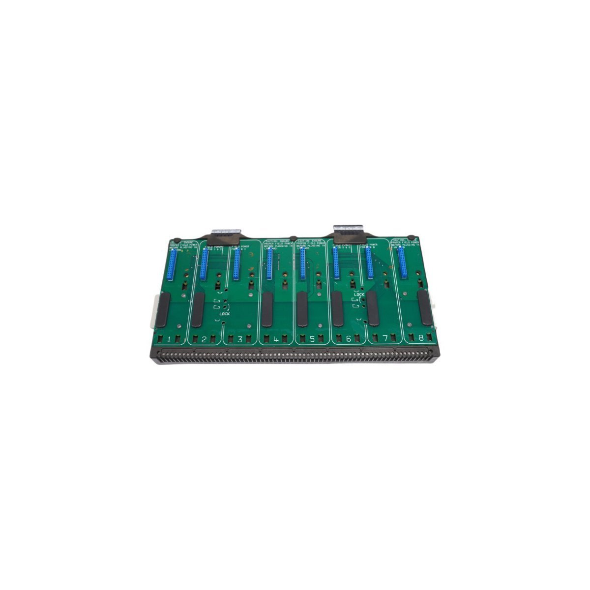
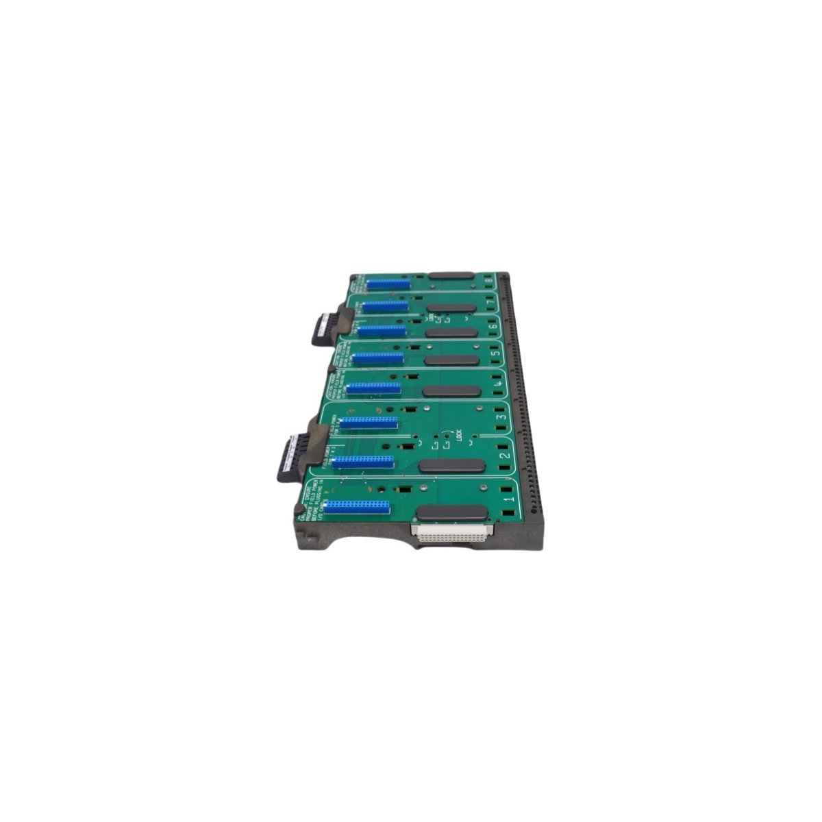
Configured for high-density signal distribution in DeltaV M-series I/O Subsystem networks, the Emerson KJ4001X1-BE1 12P0818X072 (KJ4001X1-BE1 8-Wide IO Carrier) provides direct physical/electrical execution.
Suffix Breakdown & Model Matrix
Model
Description
KJ4001X1-BE1
DeltaV M-series 8-wide I/O carrier with integrated shielding
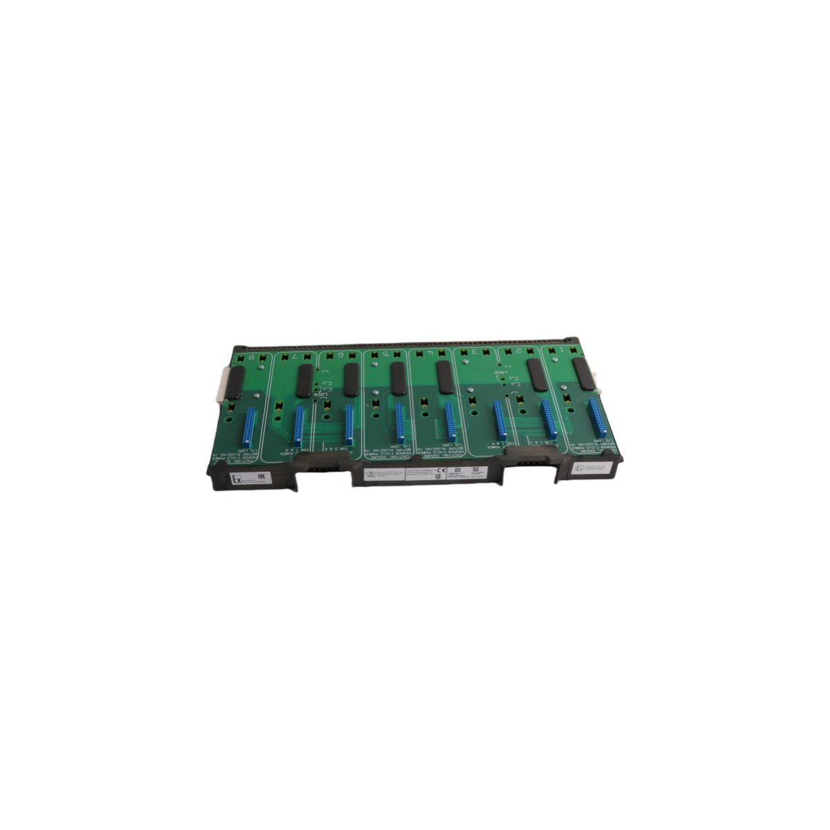
The KJ4001X1-BE1 acts as the physical backbone for M-series I/O card mounting and signal termination. This carrier features a shielded design to isolate backplane communications from external electromagnetic interference (EMI). It supports 8-wide module placement, facilitating high-density I/O configurations while maintaining strict electrical separation between signal loops. The carrier integrates with the DeltaV system bus to manage data throughput and power distribution across all installed I/O modules. Users must adhere to proper shielding ground practices to ensure the 4-20 mA HART loop protocol signals maintain their rated accuracy during transmission.
Frequently Asked Questions
Q: Does the carrier support hot-swapping of I/O modules?A: Yes, the DeltaV M-series backplane architecture supports the removal and insertion of I/O modules while the carrier is energized, provided the specific I/O module type allows for such operations under the defined safety and process conditions.Q: How does the integrated shielding function?A: The carrier incorporates a conductive chassis plane that connects to the system earth ground. This plane acts as an EMI shield for the underlying bus communication traces, preventing noise coupling into sensitive analog input circuits.
Field Installation Guidelines
Mount the carrier horizontally on a standard DIN-rail or chassis plate within the control cabinet.
Verify that the carrier backplane ground lug connects securely to a low-impedance earth ground to satisfy EMI protection requirements.
Ensure all I/O modules seat firmly into the connector slots to prevent backplane bus communication timeouts or intermittent signal loss.
Maintain adequate clearance above and below the carrier to facilitate heat dissipation and cabling access.
Inspect all terminal blocks for loose connections after installation to ensure low-resistance contact for all signal and power circuits.
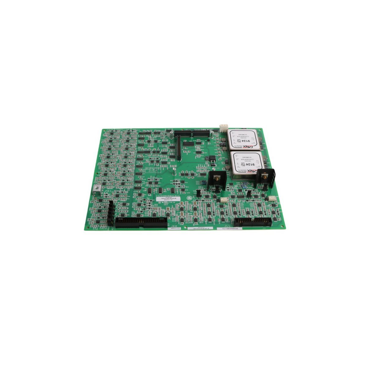
The GE IS210MVRBH1A is a high-accuracy I/O interface board for Mark VIe systems. It supports R/S/T signal processing, real-time thermal monitoring, and IONet connectivity.
The GE IS200SCSAS1AEB is a Simplex Serial Communication (SSCA) I/O board for Mark VIe systems. It supports six channels of RS-232, RS-485, and RS-422 communication, featuring an on-board ID chip for automated diagnostics and flexible DIN-rail or cabinet mounting options.
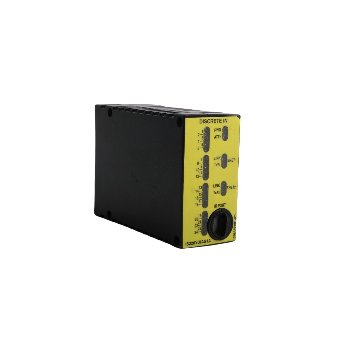
The GE IS220PDIOH1A is a high-performance Mark VIe Discrete I/O module providing 24 contact inputs and 12 relay outputs. Featuring dual Ethernet redundancy and opto-isolation, it ensures reliable digital signal management for gas turbine and DCS applications.
The Emerson KJ3223X1-BA1 (VE4003S2B6) is a high-performance DeltaV S-series input module designed for seamless DCS integration. Featuring hot-swappable hardware and 12P2871X022 compatibility, it ensures reliable signal processing for demanding industrial automation environments.
The Emerson KJ3221X1-BA1 (12P2531X062) is a high-reliability DeltaV Redundant I/O Baseplate designed for Series 2 systems. It enables seamless module redundancy and hot-swappable maintenance for critical DCS applications in harsh industrial environments.
The GE IS220YPROS1A is a high-speed backup protection I/O module designed for the Mark VIe control system. It provides critical overspeed monitoring and emergency shutdown logic for turbines, featuring dual-port redundancy and TMR capabilities to ensure maximum power plant safety and reliability.
The GE DS200TCQCG1BJF (TCQC) is a 32-channel Analog I/O Expander Board for the Speedtronic Mark V control system. It provides LVDT/LVDR excitation, scales 4–20 mA megawatt signals, and manages pulse rate inputs for turbine shaft speed. This RST Overflow board supports redundant architectures and features 24 jumpers for precise hardware configuration in demanding power generation environments.
The Emerson KJ4001X1-BE1 (12P0818X092) is an 8-wide I/O interface carrier with an integrated shield bar for the DeltaV M-series system.It provides a rugged, G3-certified mounting platform for 8 I/O modules, supporting LocalBus power distribution and hot-swappable expansion in hazardous industrial environments.
The Emerson KJ3221X1-BA1 (VE4003S2B2) is a 32-channel, 24VDC discrete output module for DeltaV S-series systems. Featuring advanced loop diagnostics, high-density switching, and hot-swap capability, this module provides reliable and fault-tolerant control for solenoid valves and relays in demanding process environments.
We are committed to protecting your privacy. The information collected here is strictly used to provide the requested quotes, technical support, and relevant industrial automation solutions.