Sale!
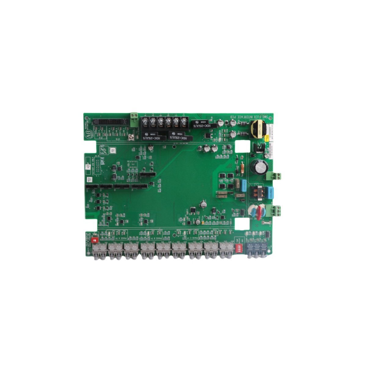
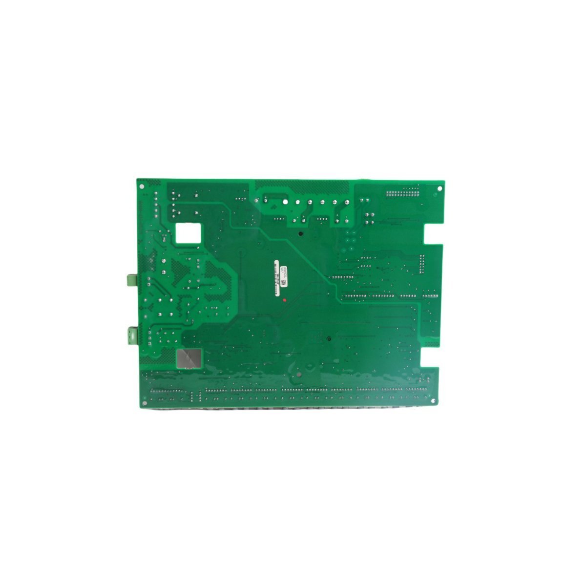
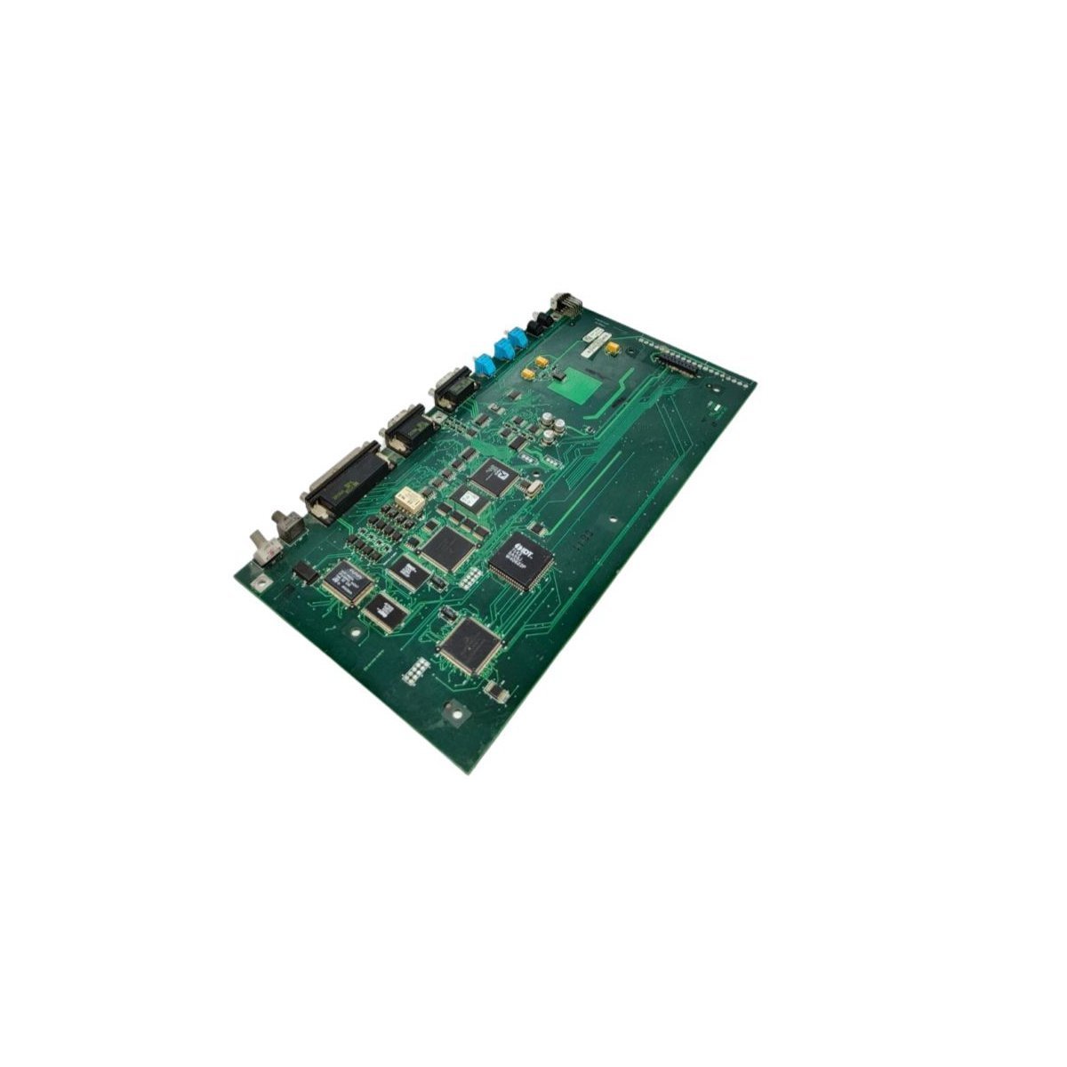
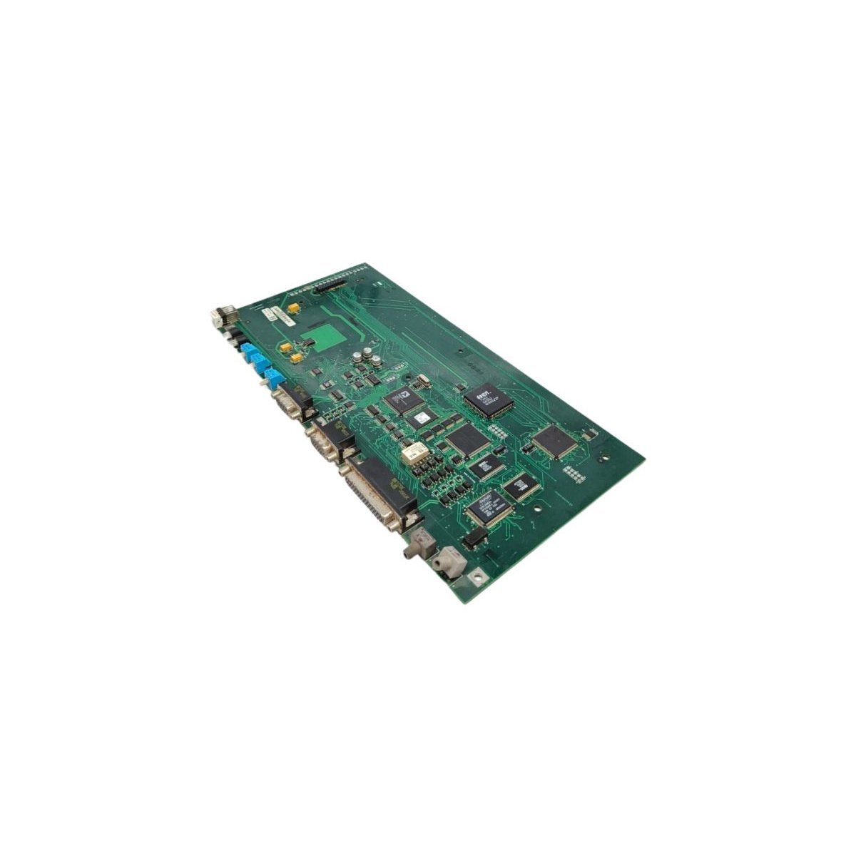
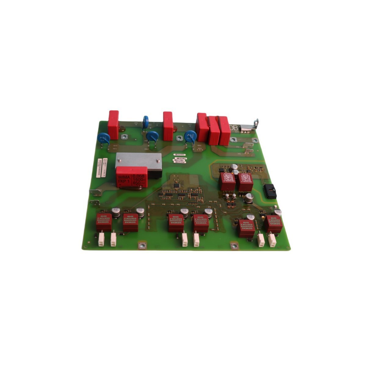
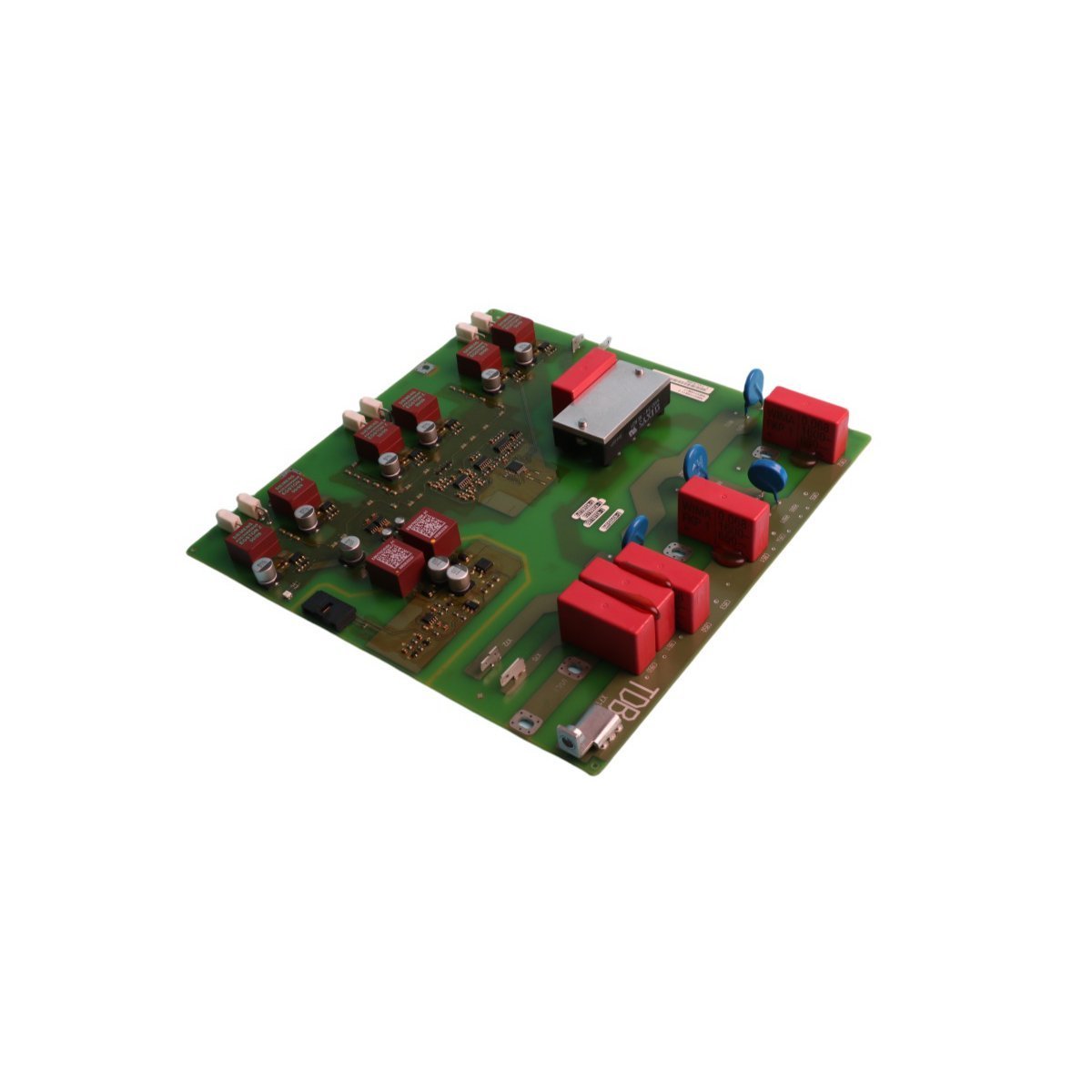
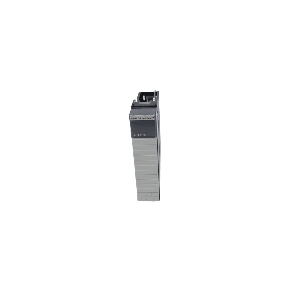
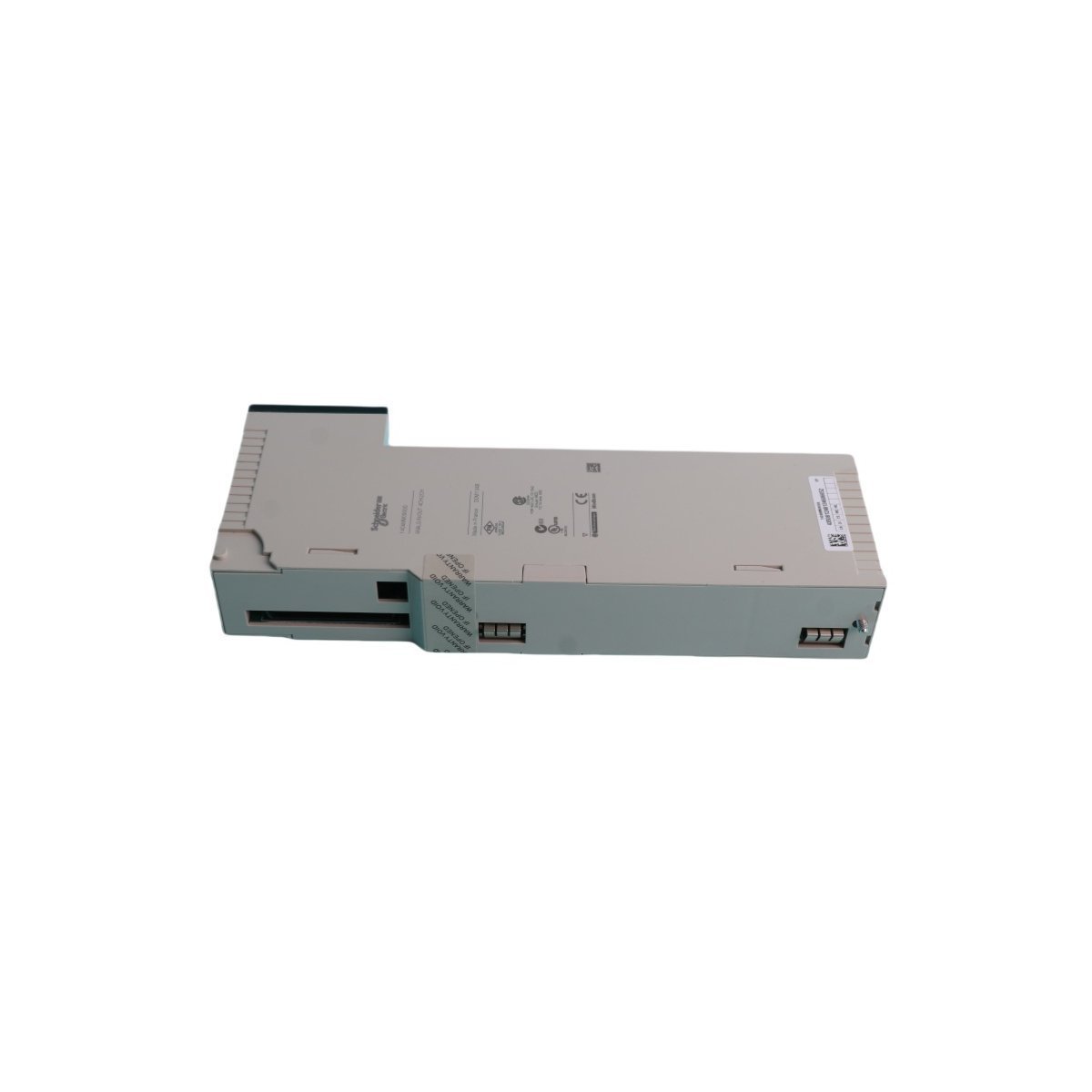
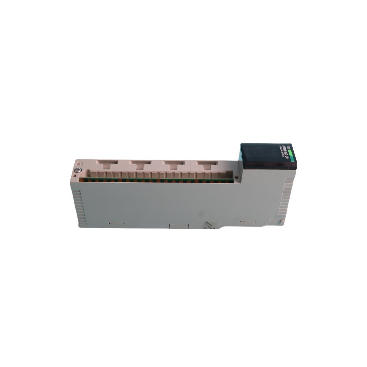
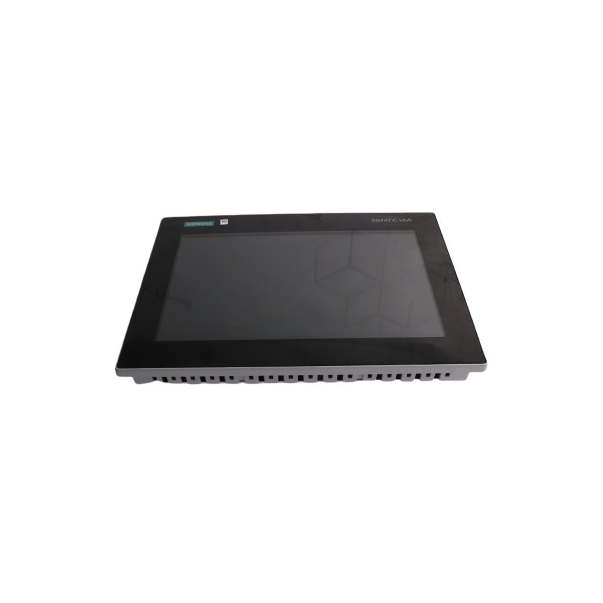
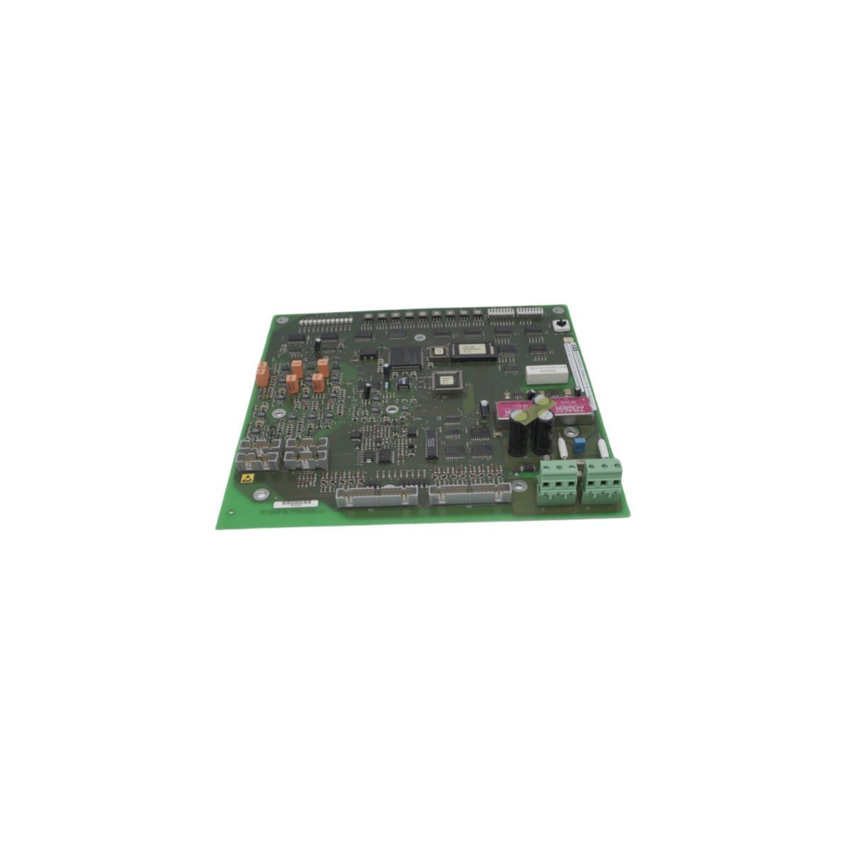
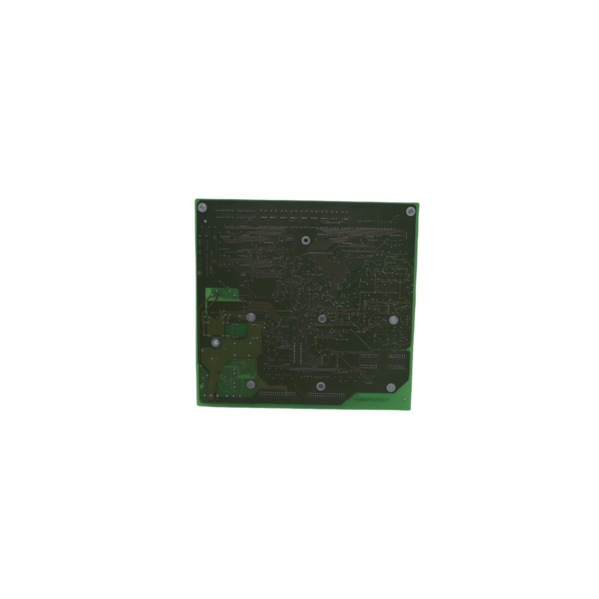
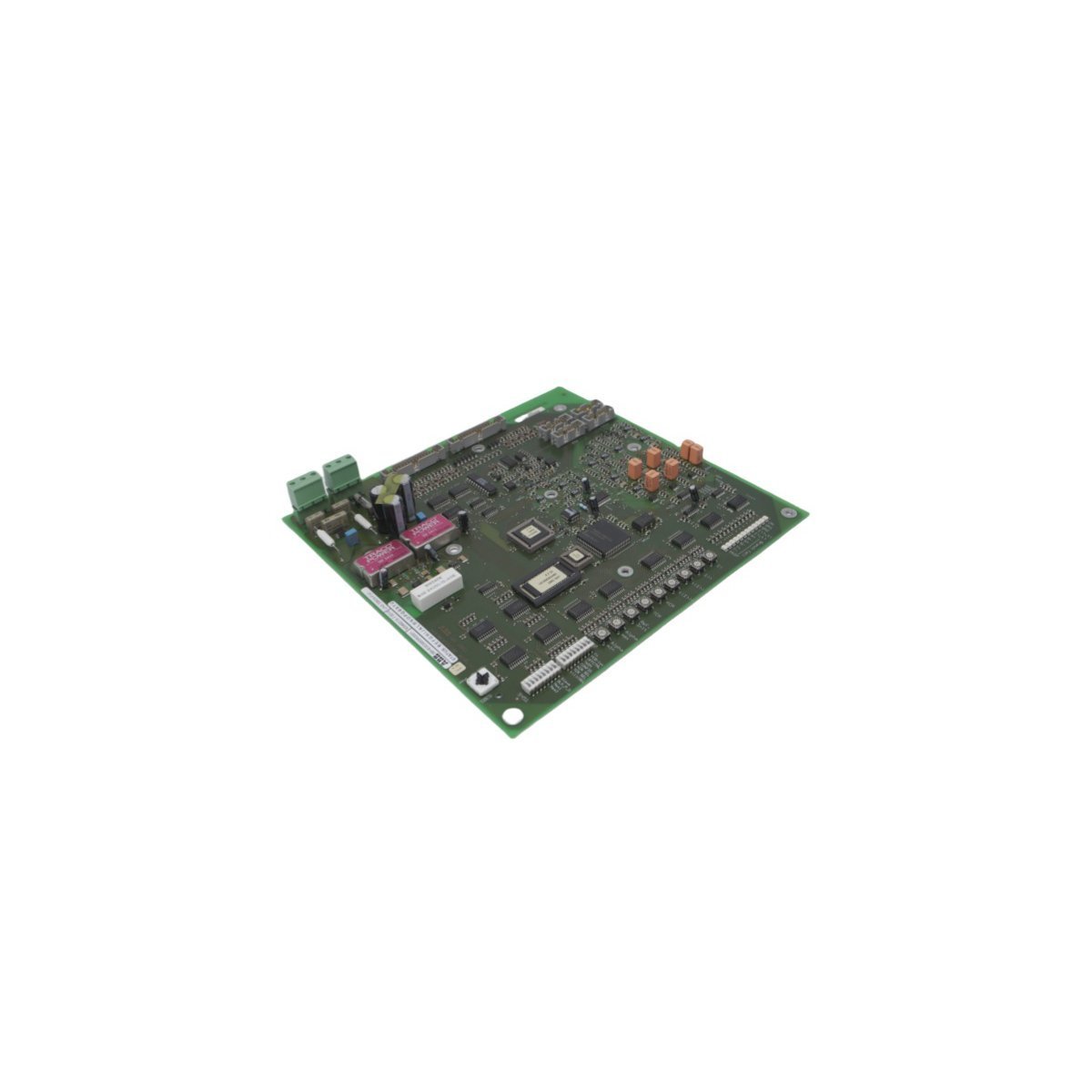
Allen Bradley 80190-440-03-R Interface Board
Configured for signal interfacing and communication management in PLC-based automation systems, the Allen Bradley 80190-440-03-R (80190-440-03-R Interface Board) provides direct physical and electrical execution for motor control coordination.
Hardware Specifications
| Parameter | Specification |
|---|---|
| Model | 80190-440-03-R |
| Brand | Allen Bradley |
| Origin | USA |
| Weight | 0.46 kg |
| Dimensions | 27.8 x 21.4 x 2.8 cm |
| Operating Temp | Standard industrial range |
| Power Consumption | System dependent |
| Module Type | Interface Board |
Control System Integration Characteristics
The Allen Bradley 80190-440-03-R is engineered to facilitate deterministic data exchange within control architectures. It supports robust backplane bus communication, ensuring signal integrity for soft-start and drive-control peripherals. The module's circuitry is optimized for I/O density scaling, allowing for consistent signal propagation across complex, multi-node network topologies. Firmware compatibility ensures this hardware remains responsive to system-level configuration changes, maintaining timing precision required for synchronized motor start-up and protection sequences.Frequently Asked Questions
Q: What precautions should be taken during the physical installation of this interface board to prevent signal interference?A: Ensure that the board is securely mounted to the chassis to maintain a continuous electrical ground. When terminating control cables, utilize shielded twisted-pair cabling and ensure shields are terminated at a single point to minimize electromagnetic interference (EMI) impact on data signals.Q: Does the 80190-440-03-R require specific backplane initialization procedures?A: Before energizing the backplane, verify that the module is fully seated and that all terminal connections are tight. Upon system power-up, ensure the host processor acknowledges the module presence on the bus to confirm correct address assignment and communication link establishment.Field Installation Guidelines
- Verify that all power sources to the chassis are disconnected before module installation or removal.
- Use appropriate ESD protection, including a grounded wrist strap, when handling the board to prevent damage to sensitive CMOS components.
- Inspect the connector pins for any signs of oxidation or physical damage prior to inserting the board into the backplane slot.
- Ensure adequate ventilation around the chassis to maintain ambient temperatures within the hardware rating.
- Once installed, perform a point-to-point signal verification to ensure that the interface board correctly maps control signals between the soft-start controller and the host system.