Sale!
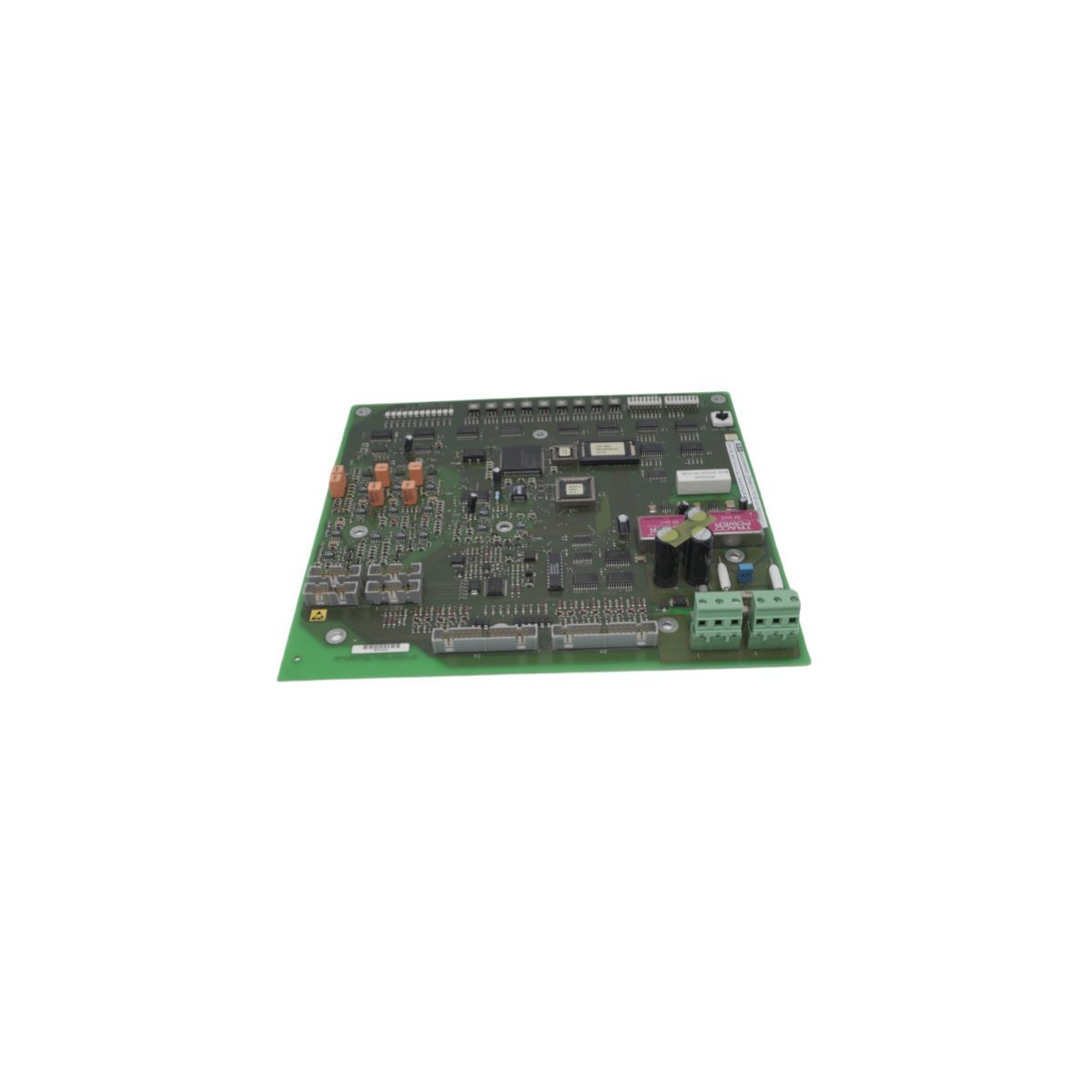
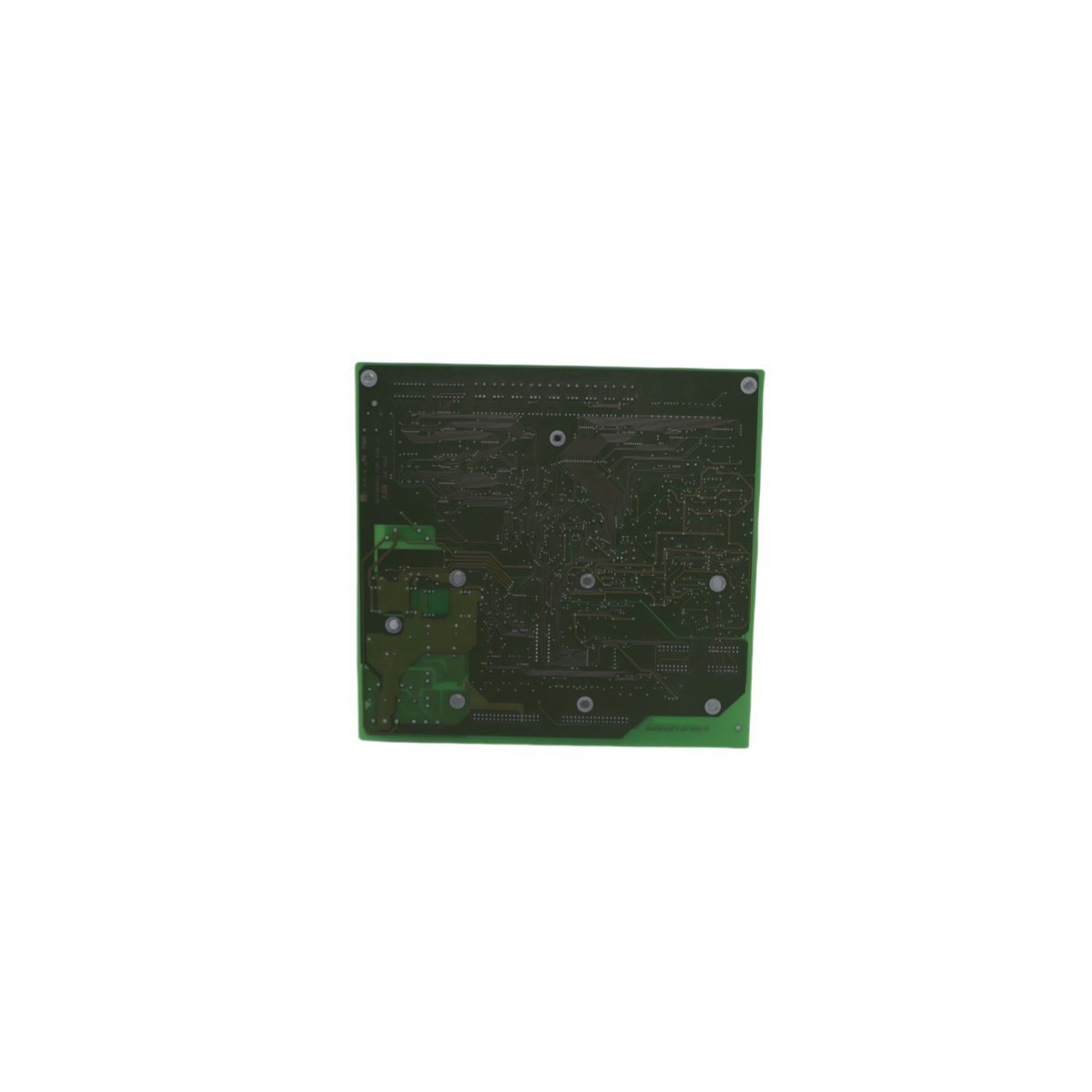
ABB 3BHE003855R0001 UNS2882A-P,V1 Interface Board
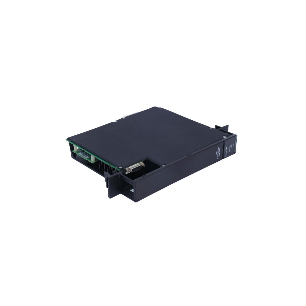
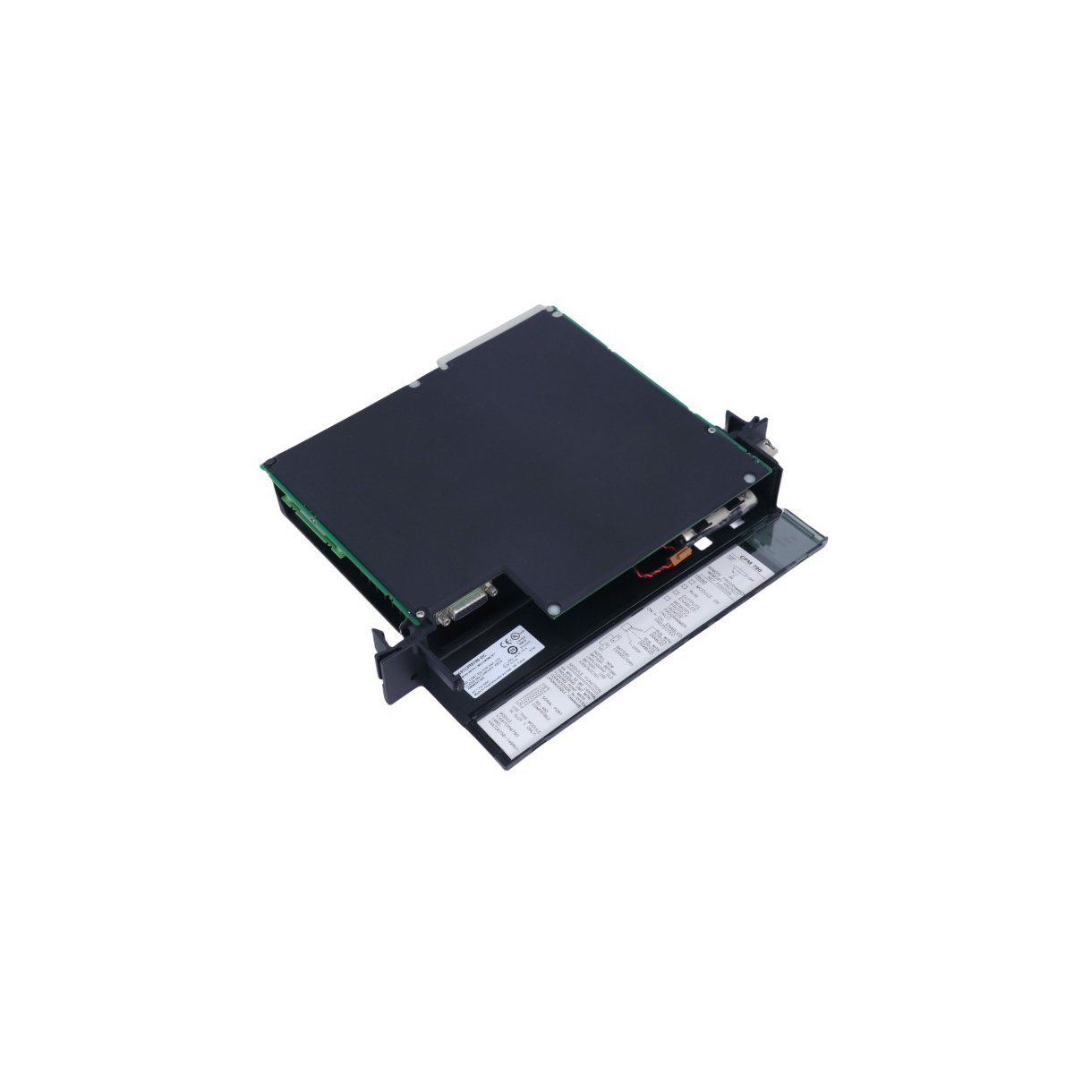
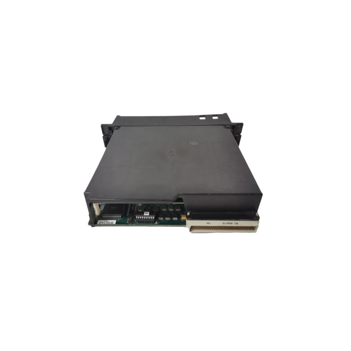
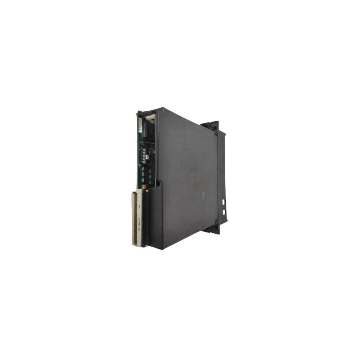
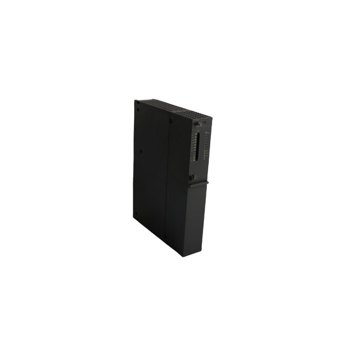
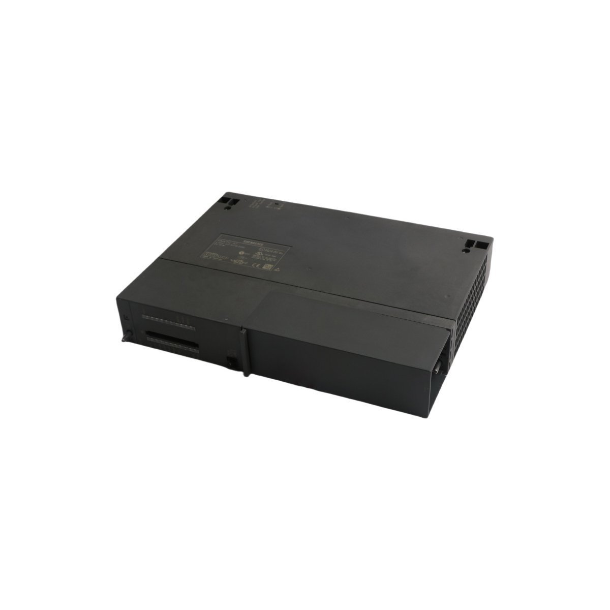
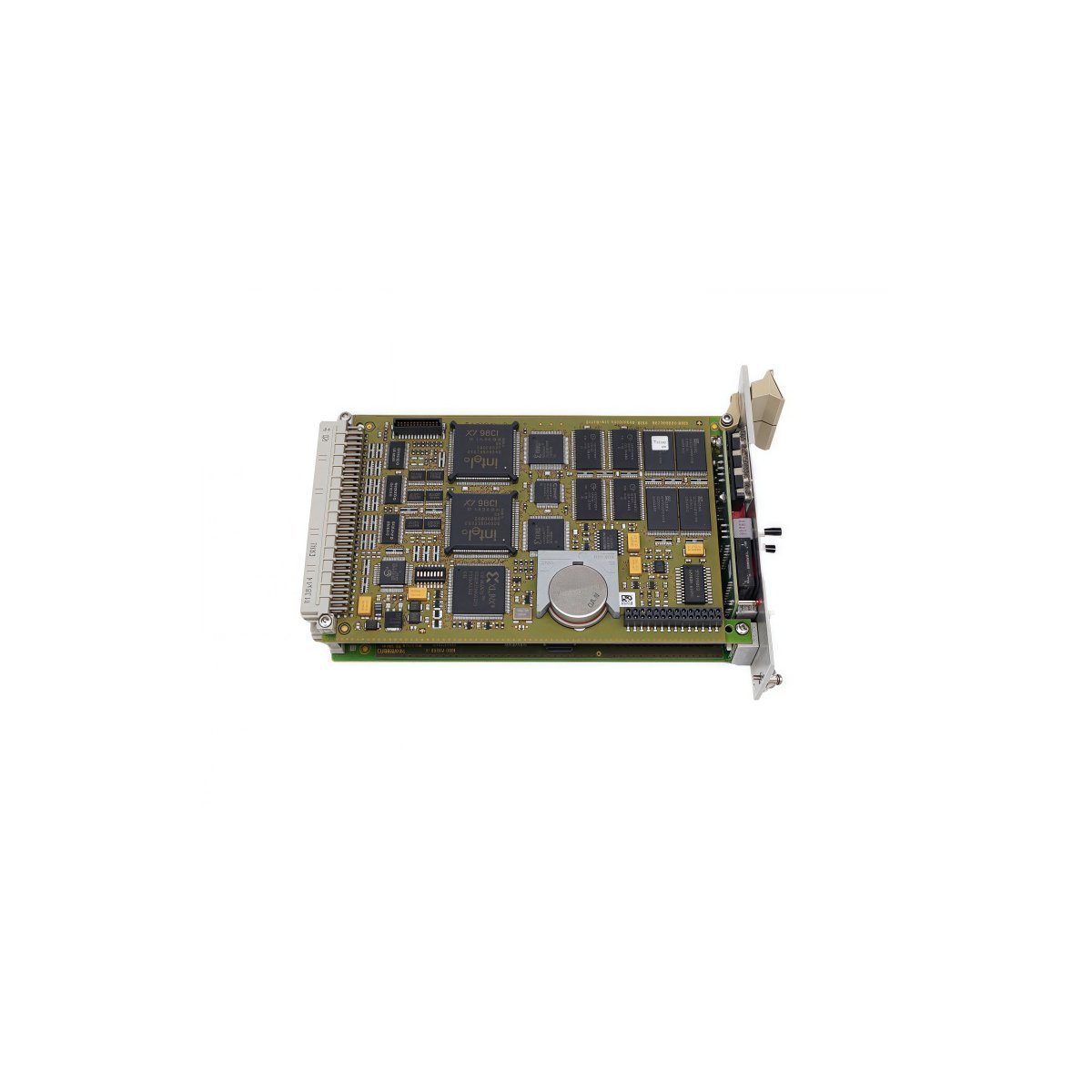
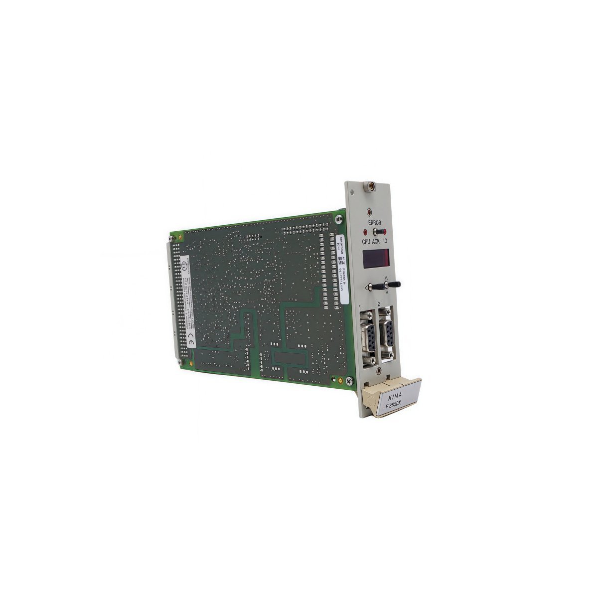
The ABB 3BHE003855R0001 UNS2882A-P,V1, also cataloged as the UNS2882A-P,V1 Interface Board, operates as a dedicated hardware component for signal processing and bus interfacing within UNITROL Excitation Systems.
Hardware Specifications
| Parameter | Specification |
|---|---|
| Model | 3BHE003855R0001 UNS2882A-P,V1 |
| Brand | ABB |
| Origin | Sweden |
| Weight | 0.36 kg |
| Dimensions | 25.5x24x3.5 cm |
| Operating Temp | -20 to +60 deg C |
| Power Consumption | 15 W nominal |
| Product Range | UNITROL Excitation Systems |
| Module Type | Interface Board |
| System Architecture | DCS / Excitation Control |
Backplane Communication Velocity and Bus Interfacing
The board manages internal deterministic data transfer across the local backplane bus, maintaining synchronization between main processing units and gate driver submodules. High-velocity bus execution limits internal signal transport latencies during transient load events. Embedded firmware compatibility validation ensures synchronized data throughput, preventing frame dropouts across real-time control cycles.Frequently Asked Questions
Q: Can the board be installed or removed under live system power?A: No, live insertion or removal is prohibited. Power down the excitation system rack prior to card extraction to avoid voltage transients and interface component damage.Q: How does the interface board maintain signal integrity during high-frequency switching?A: Dedicated board-level isolation channels and shielded bus routing protect internal logic signals from severe electromagnetic interference generated by power electronics.Field Installation Guidelines
- Ensure the main power supply to the excitation cabinet is disconnected before inserting the printed circuit board into the chassis slot.
- Observe electrostatic discharge (ESD) precautions by wearing a grounded wrist strap when handling the unshielded circuit board assembly.
- Align the card edge connectors strictly with the backplane guidance rails to avoid bending interface pins upon insertion.
- Fasten all retaining screws on the front panel to secure earth grounding continuity and prevent vibration-induced loosening.