Sale!
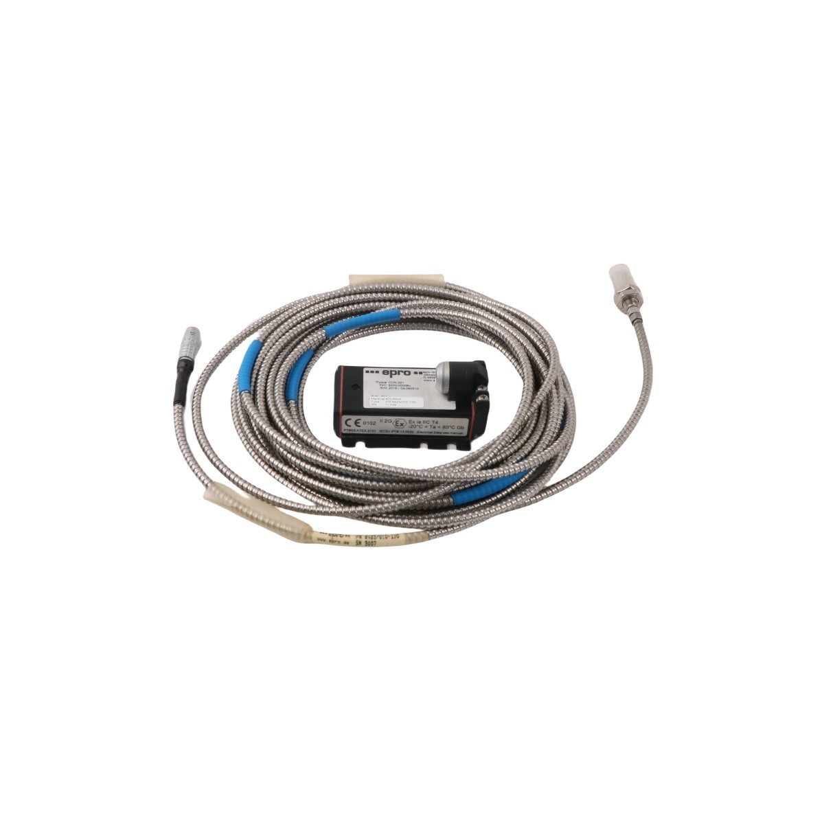
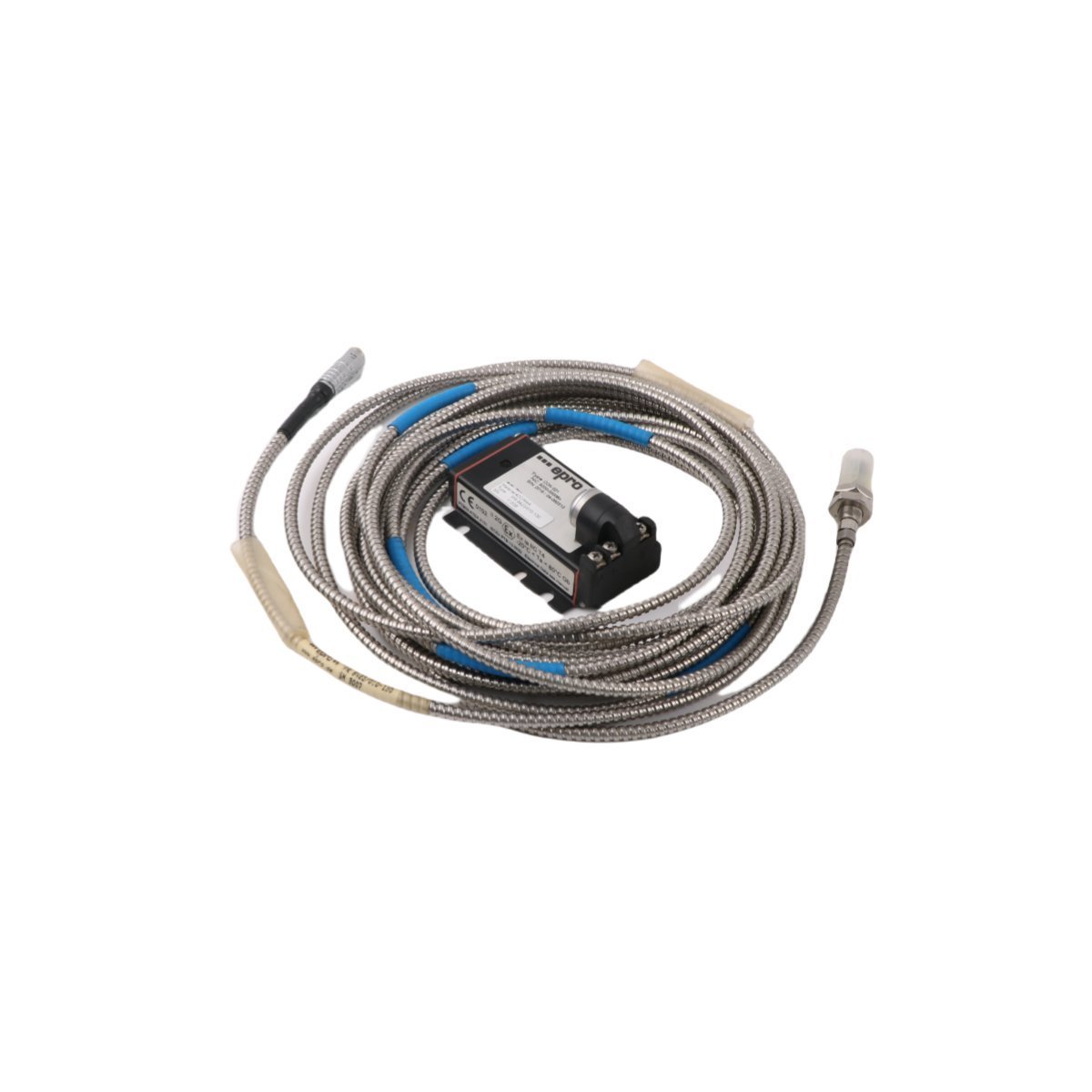
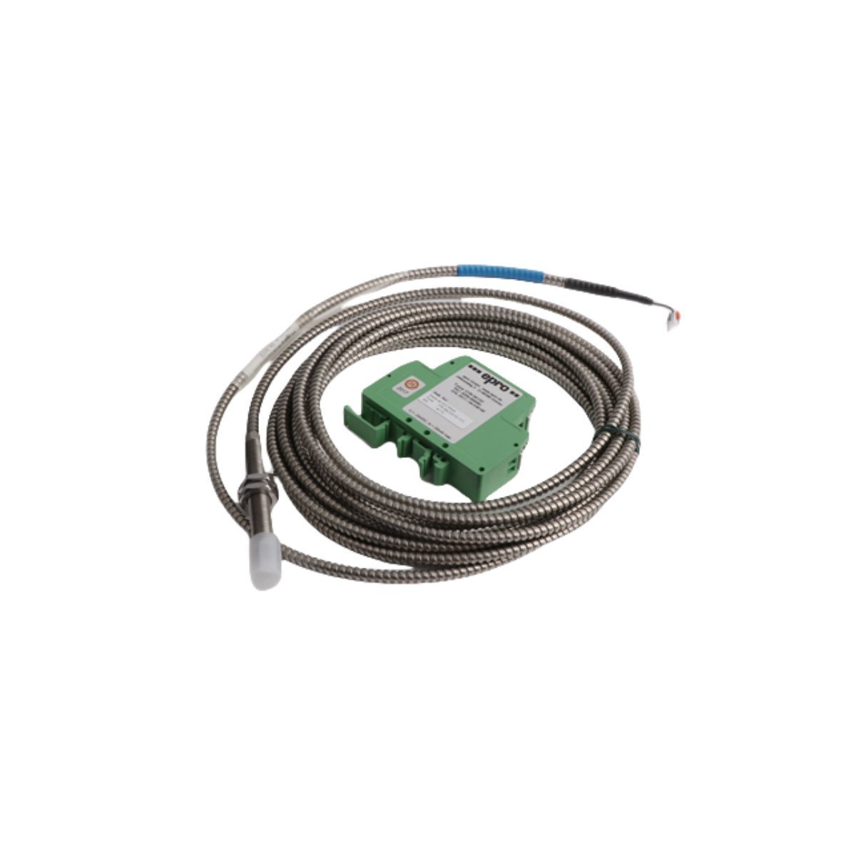
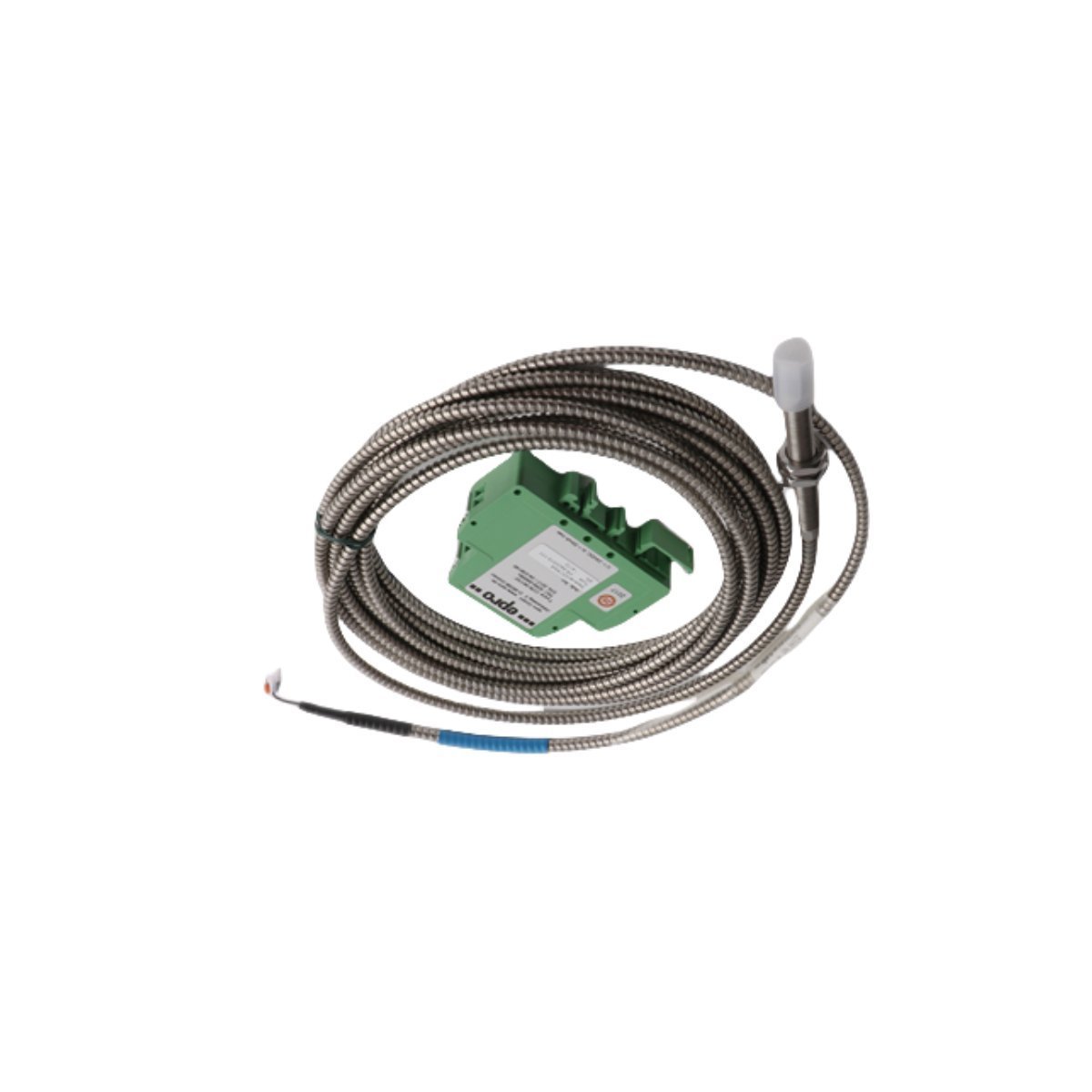
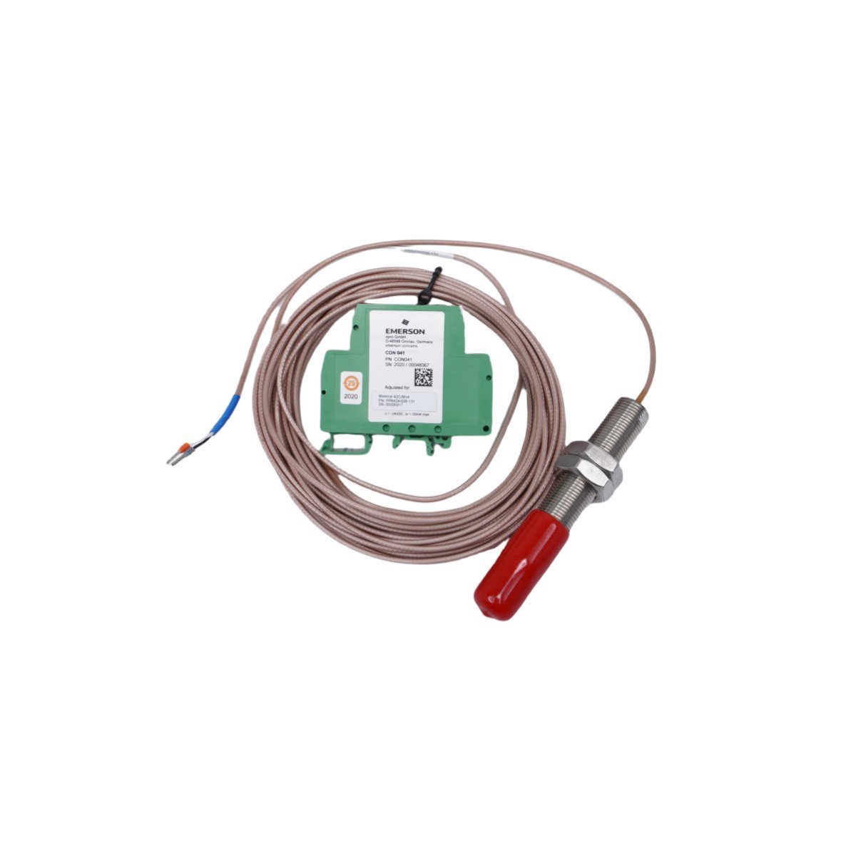
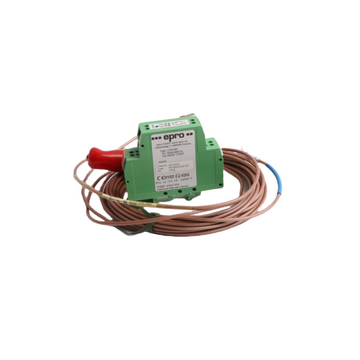
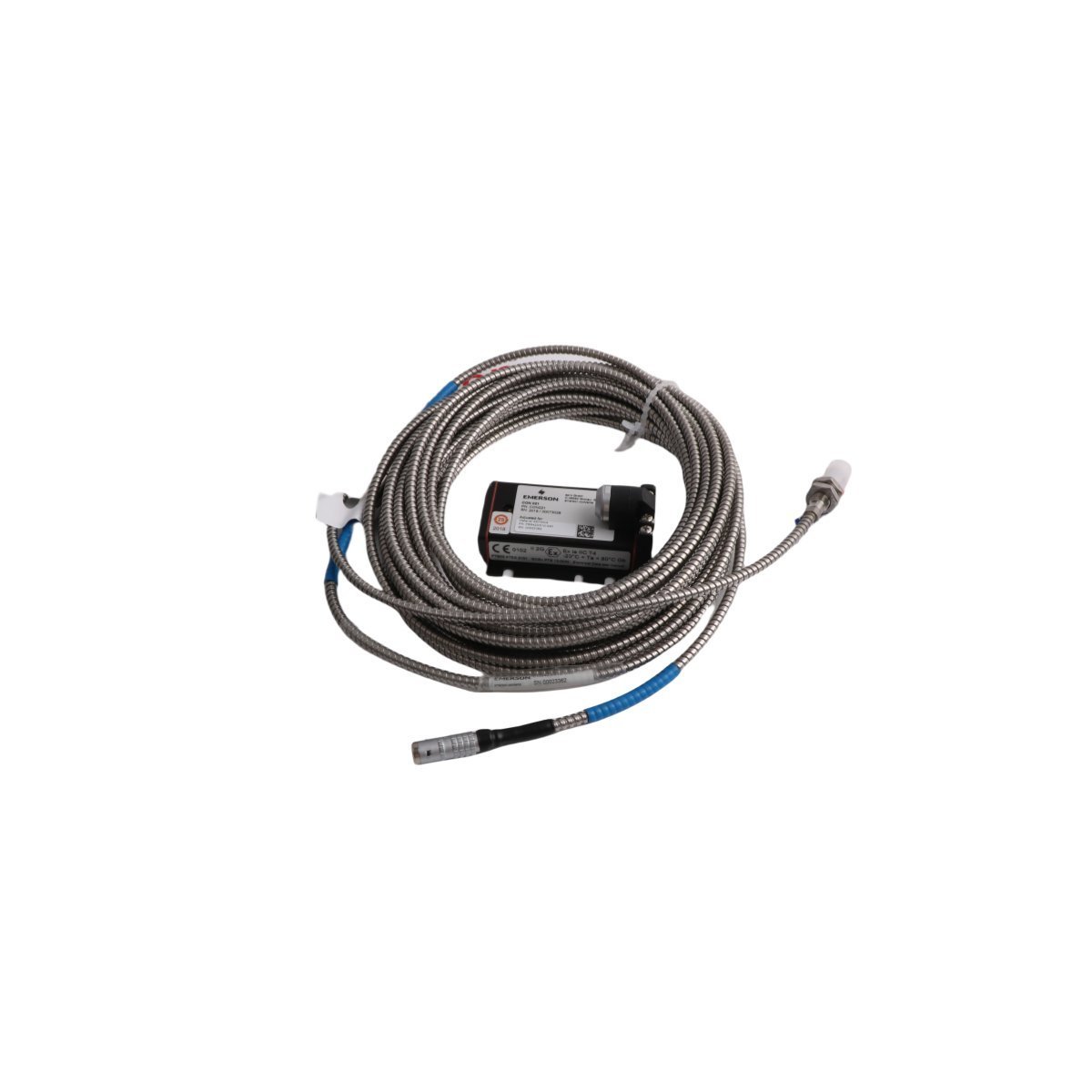
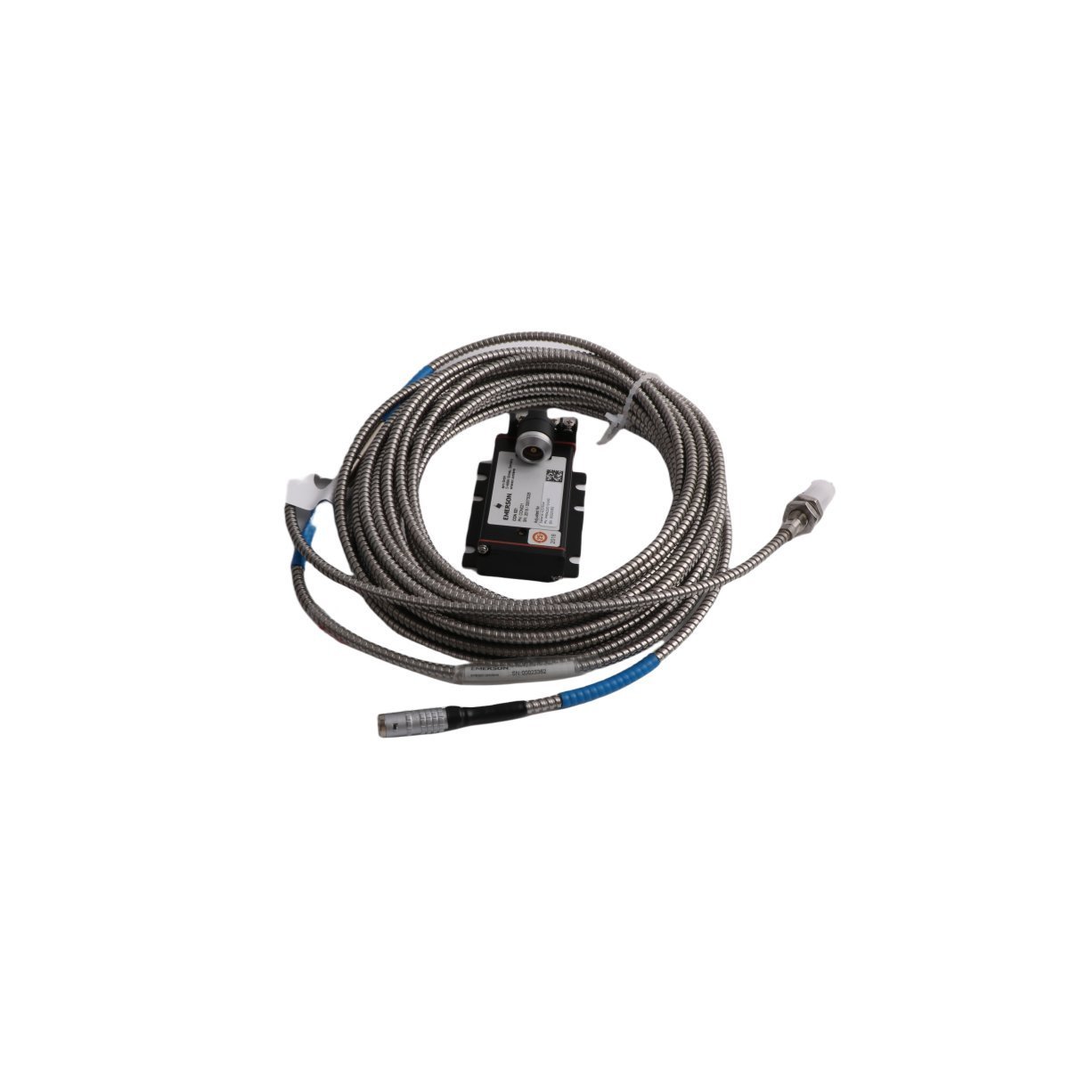
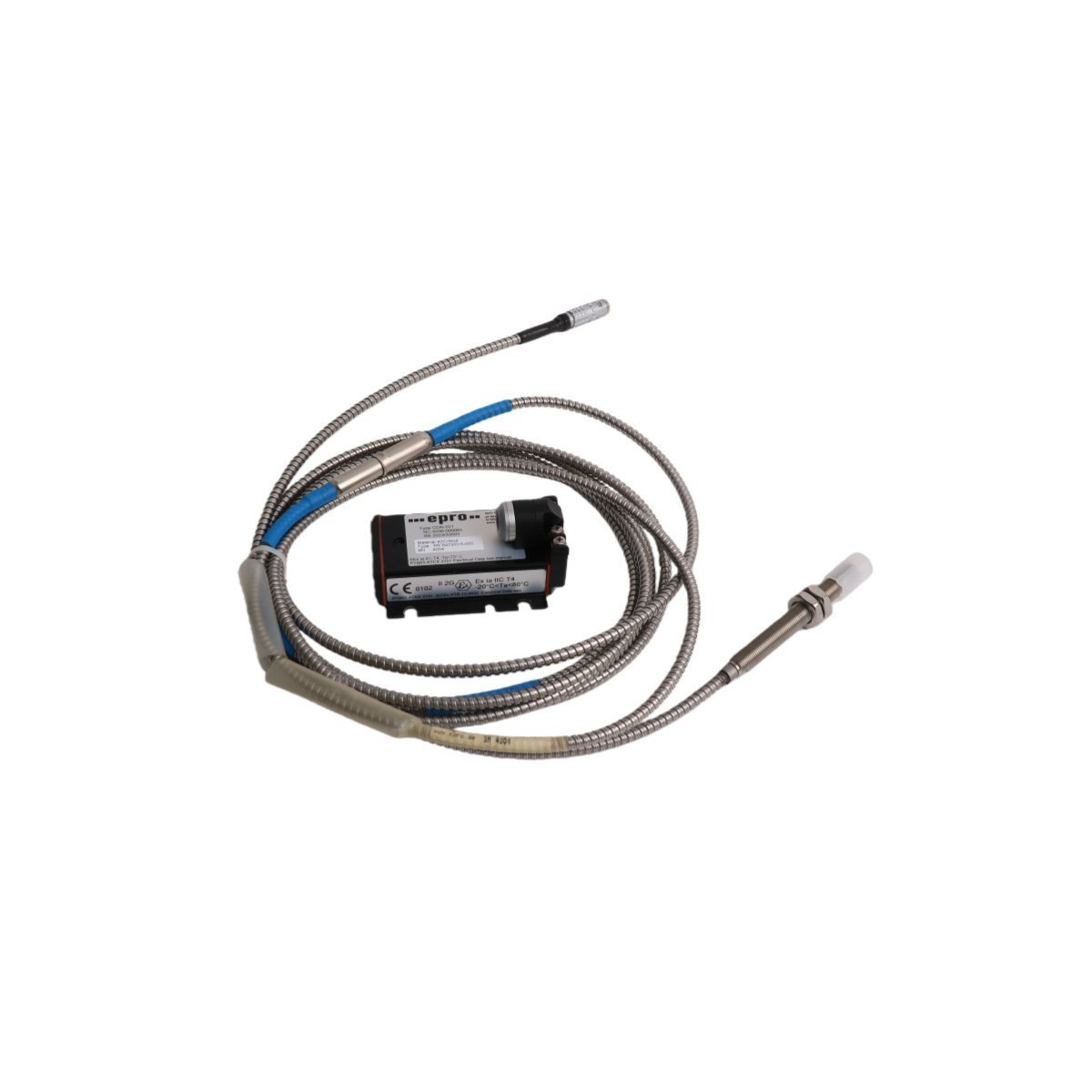
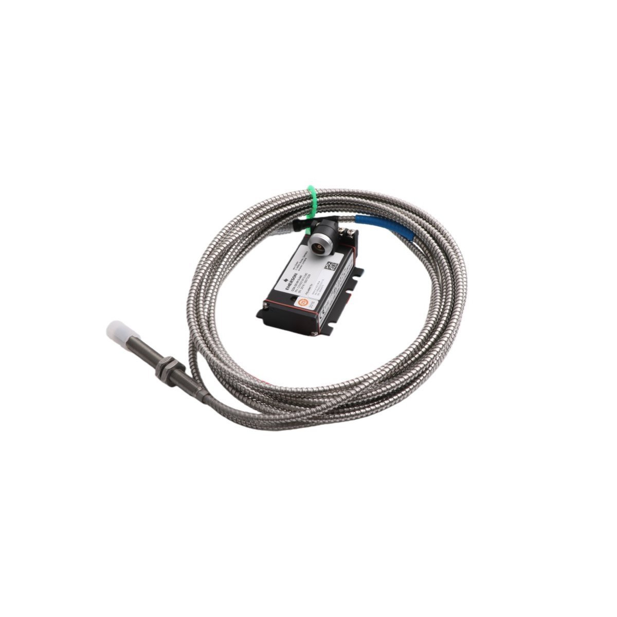
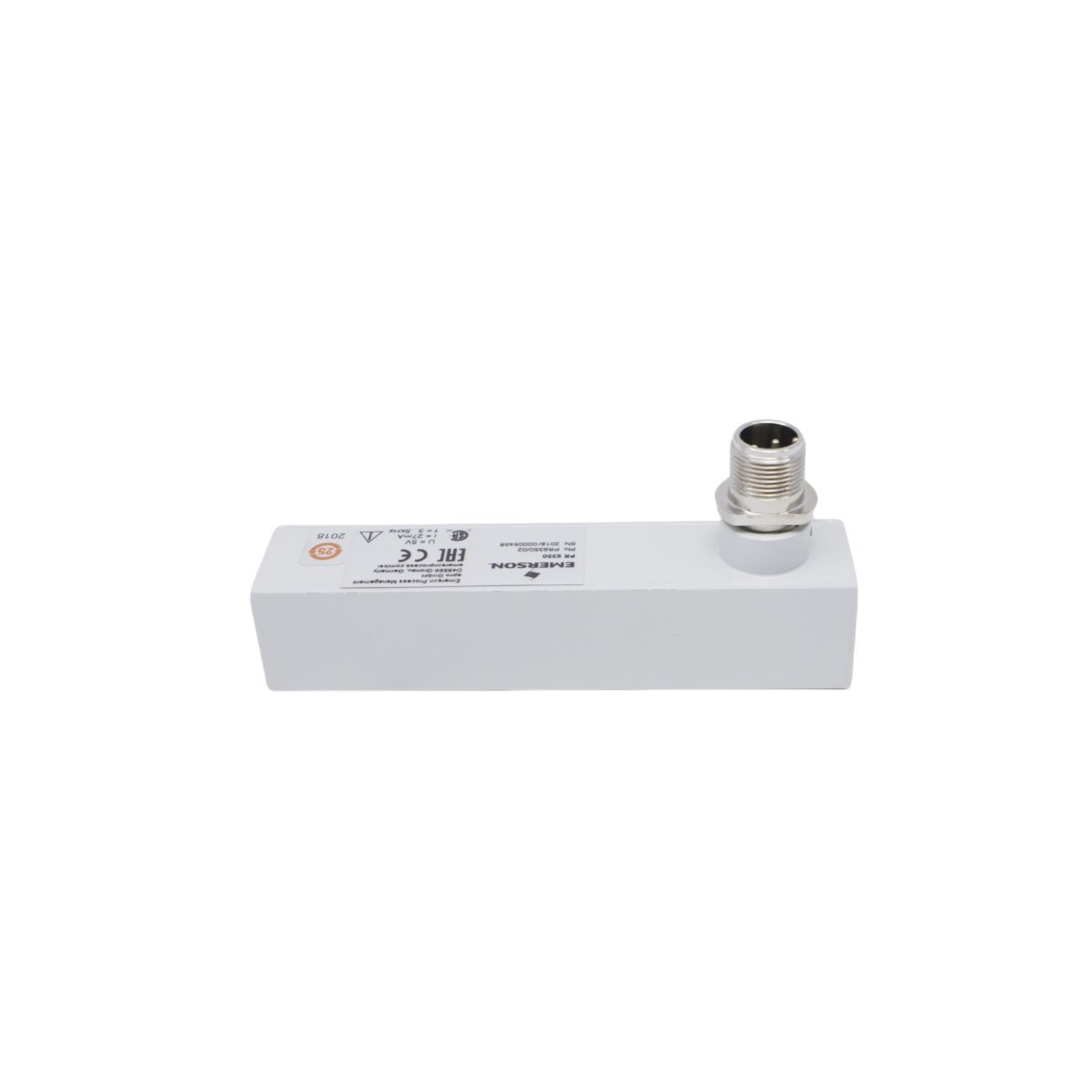
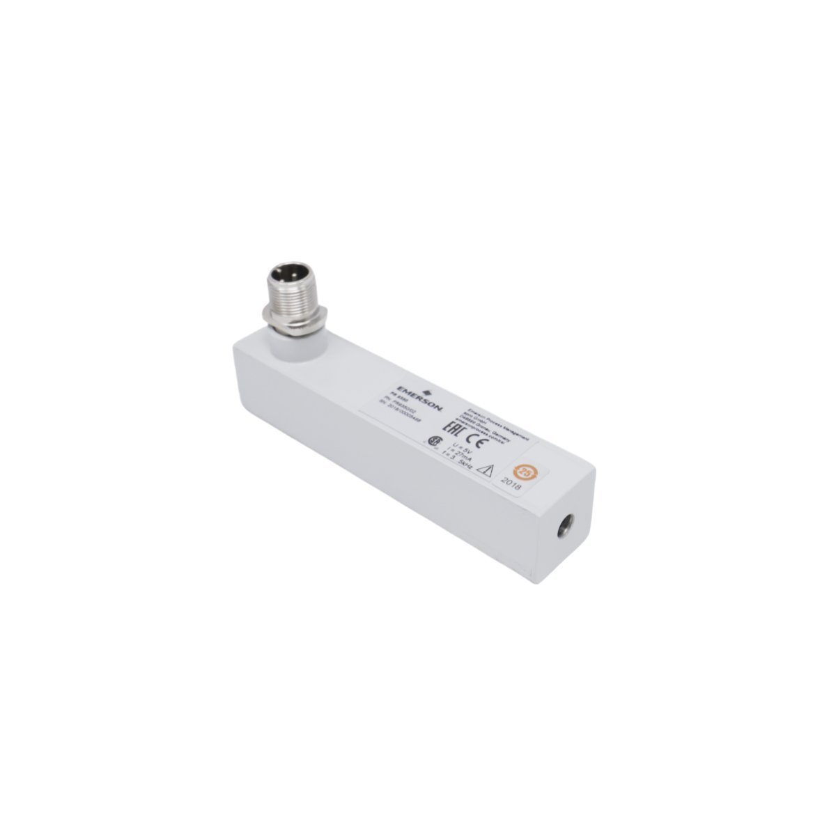
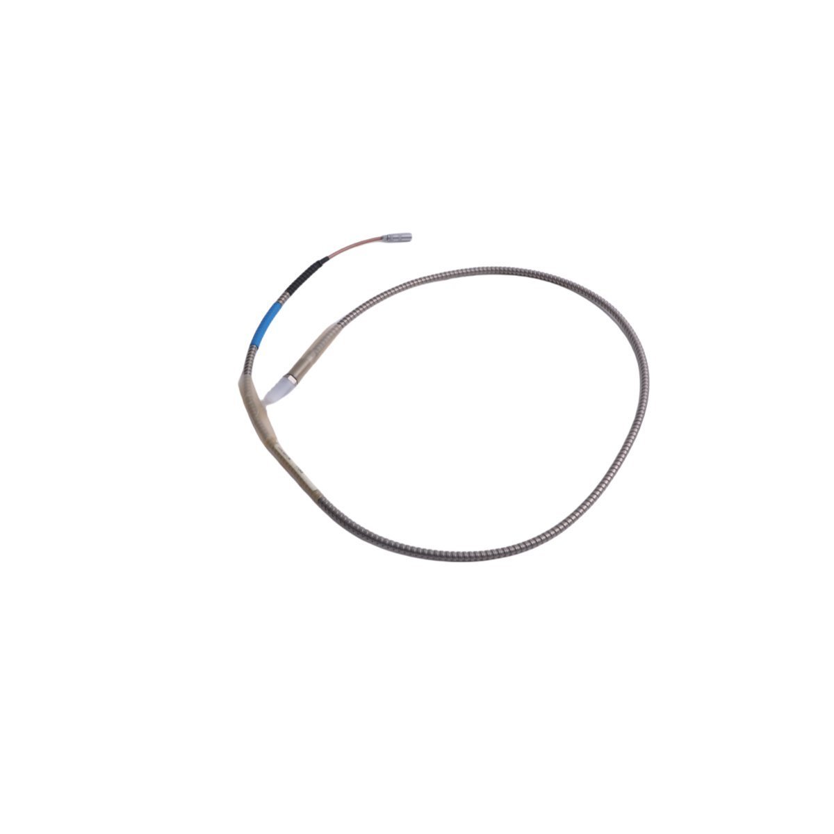
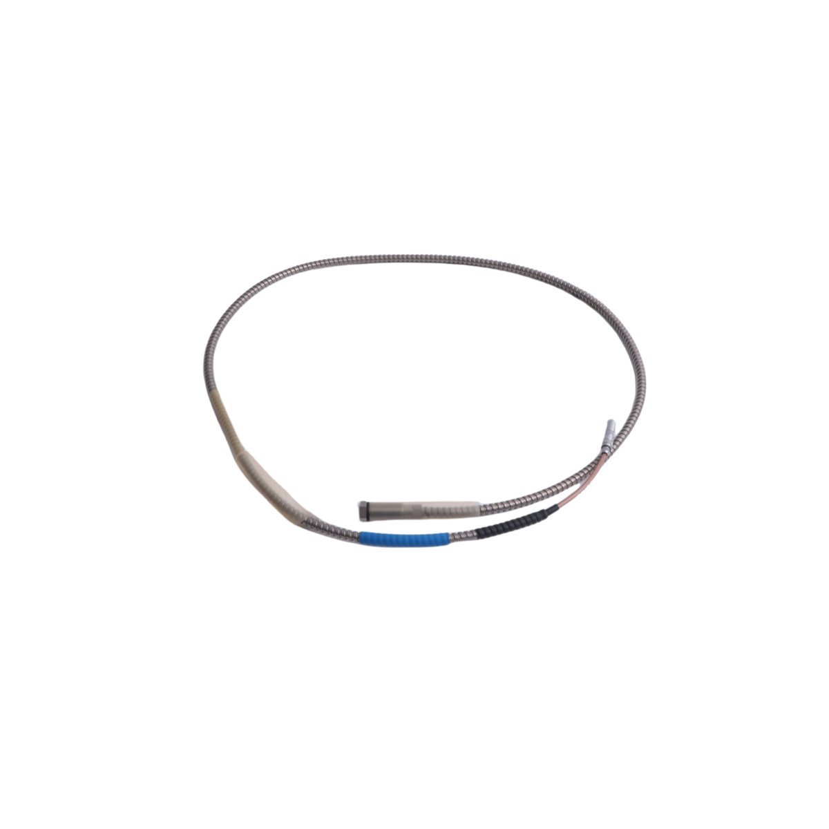
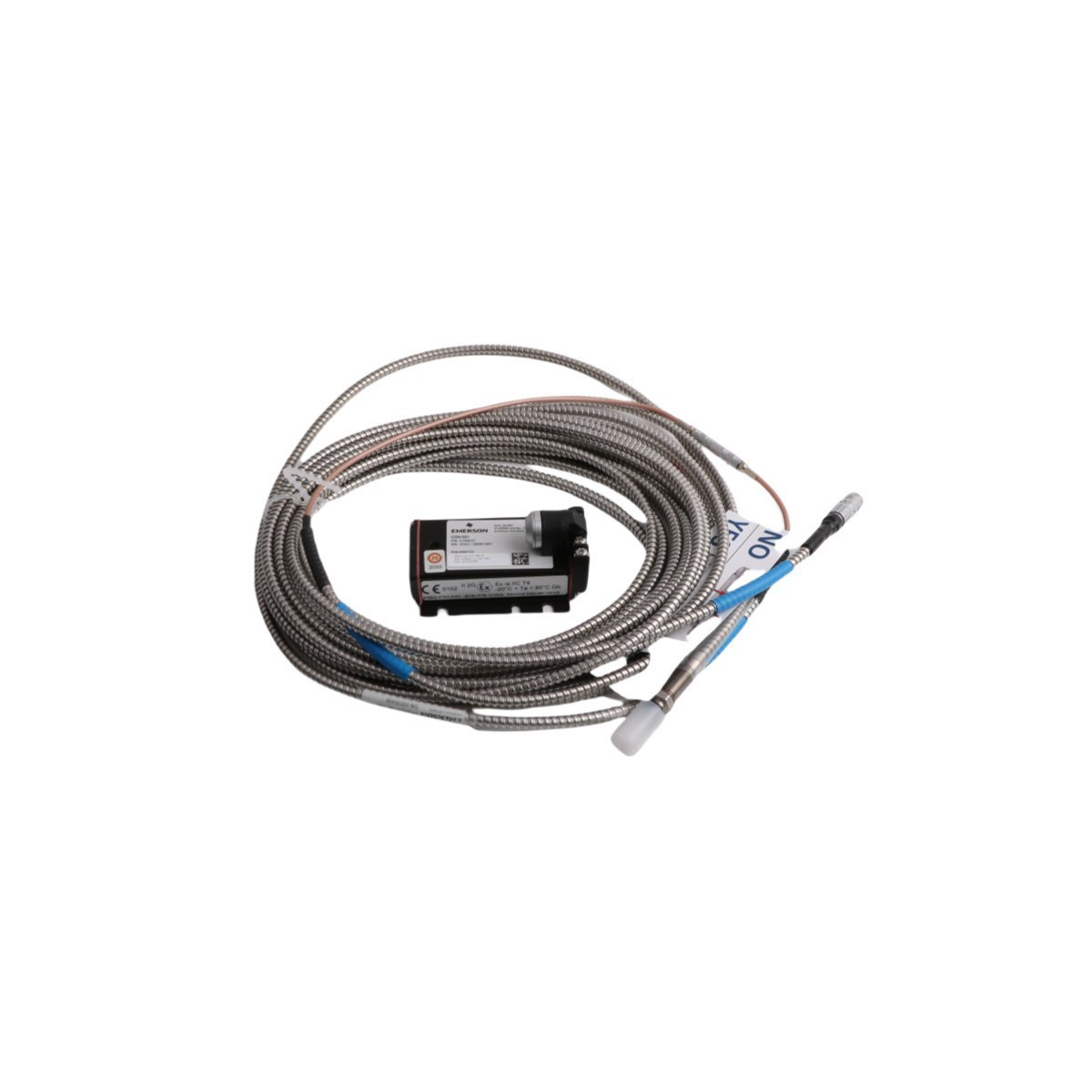
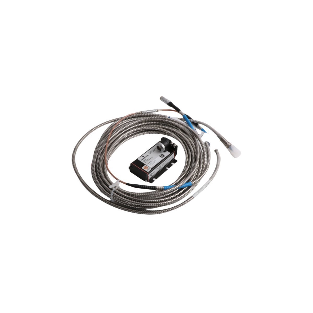
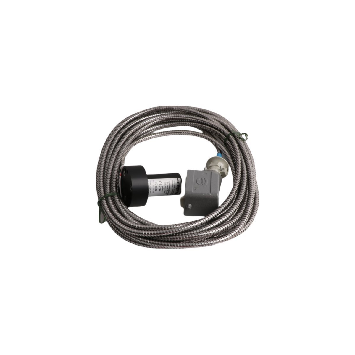
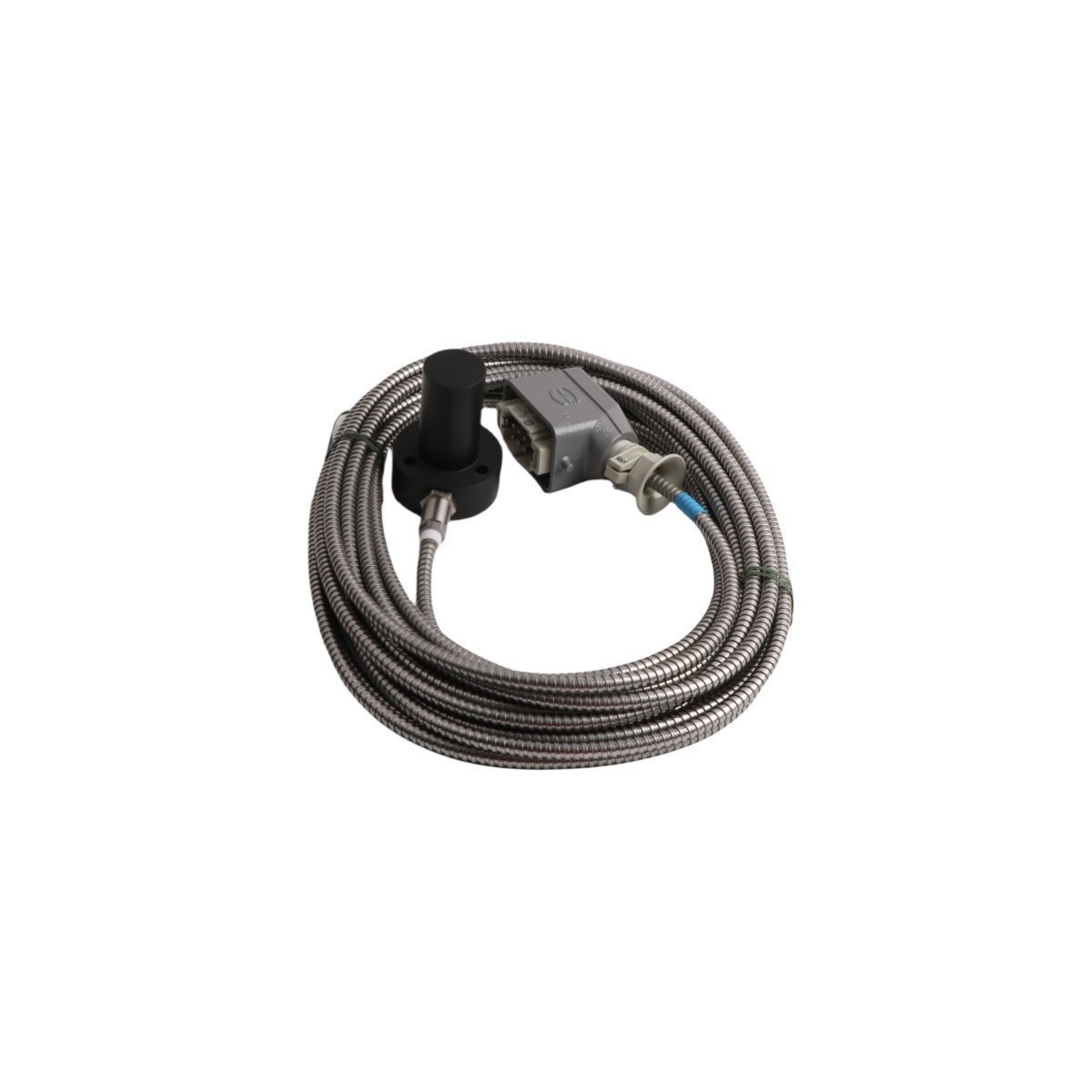
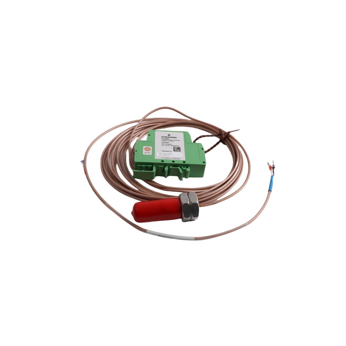
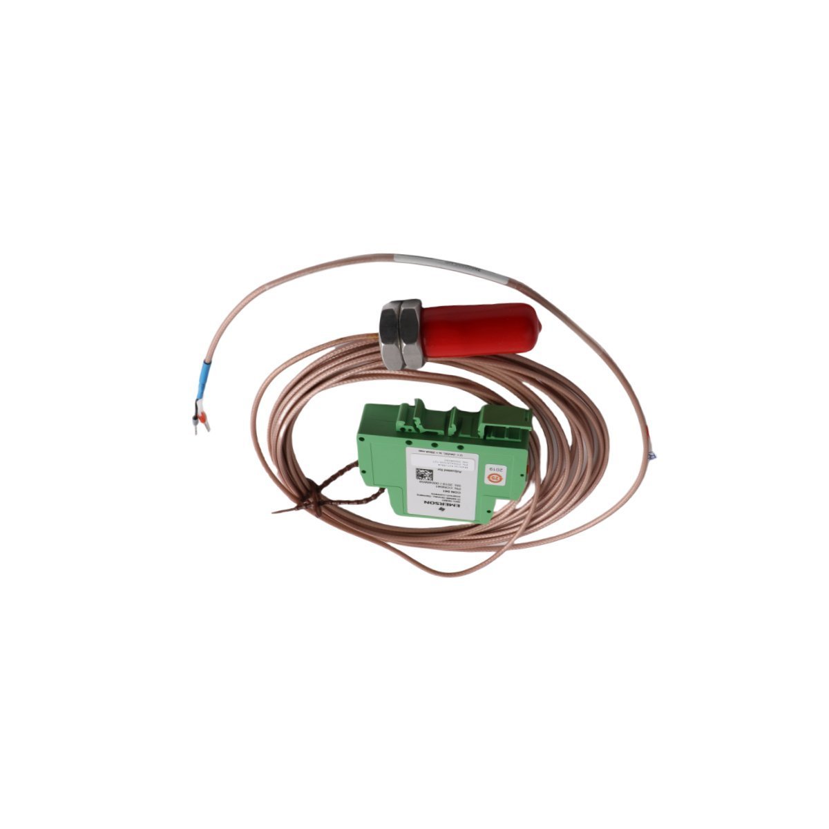
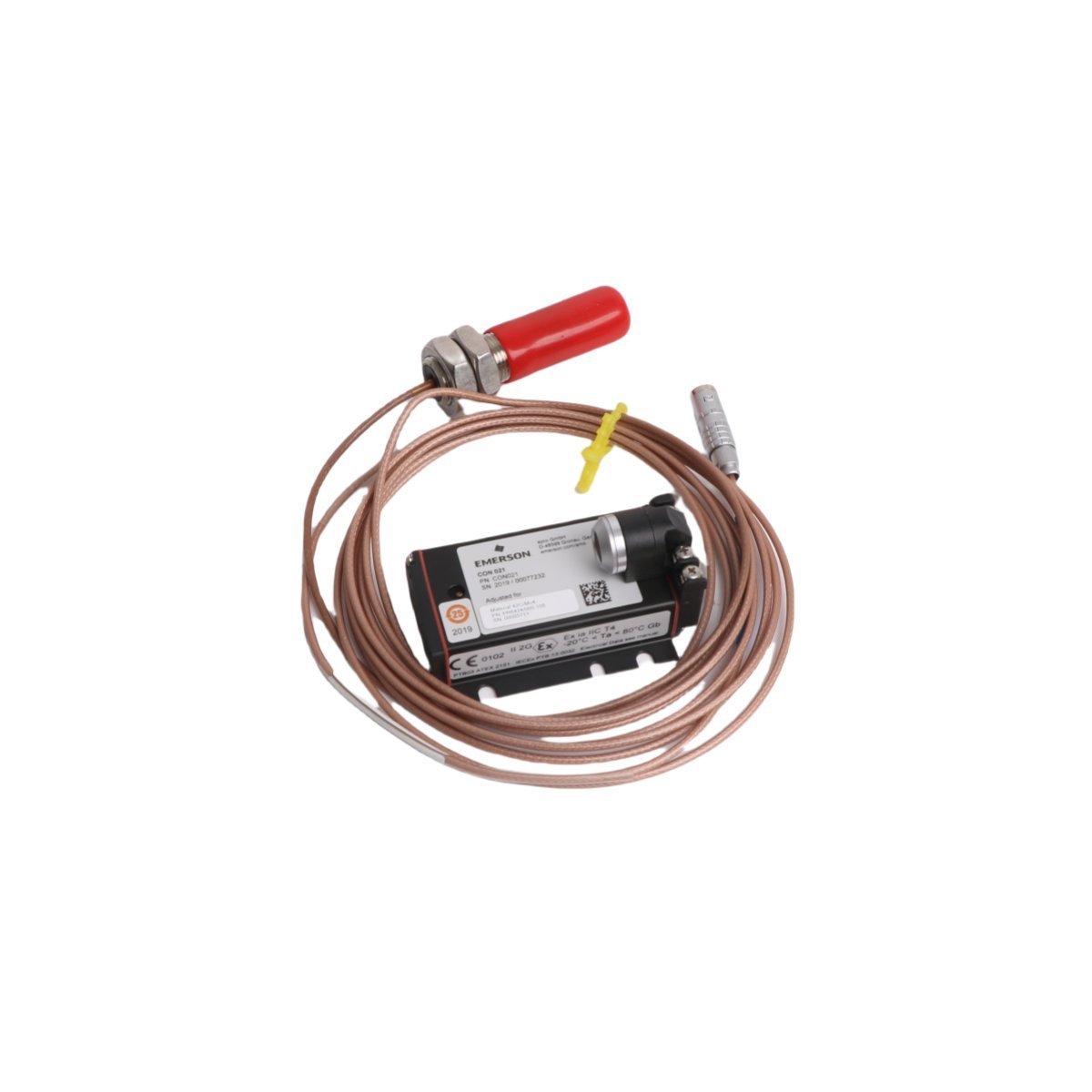
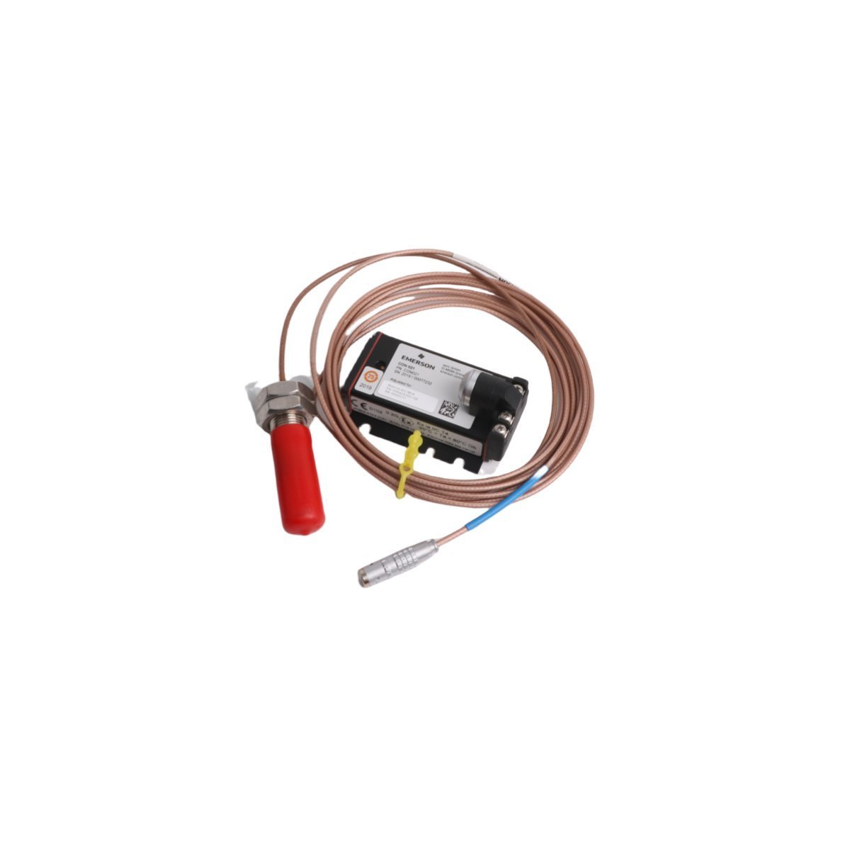
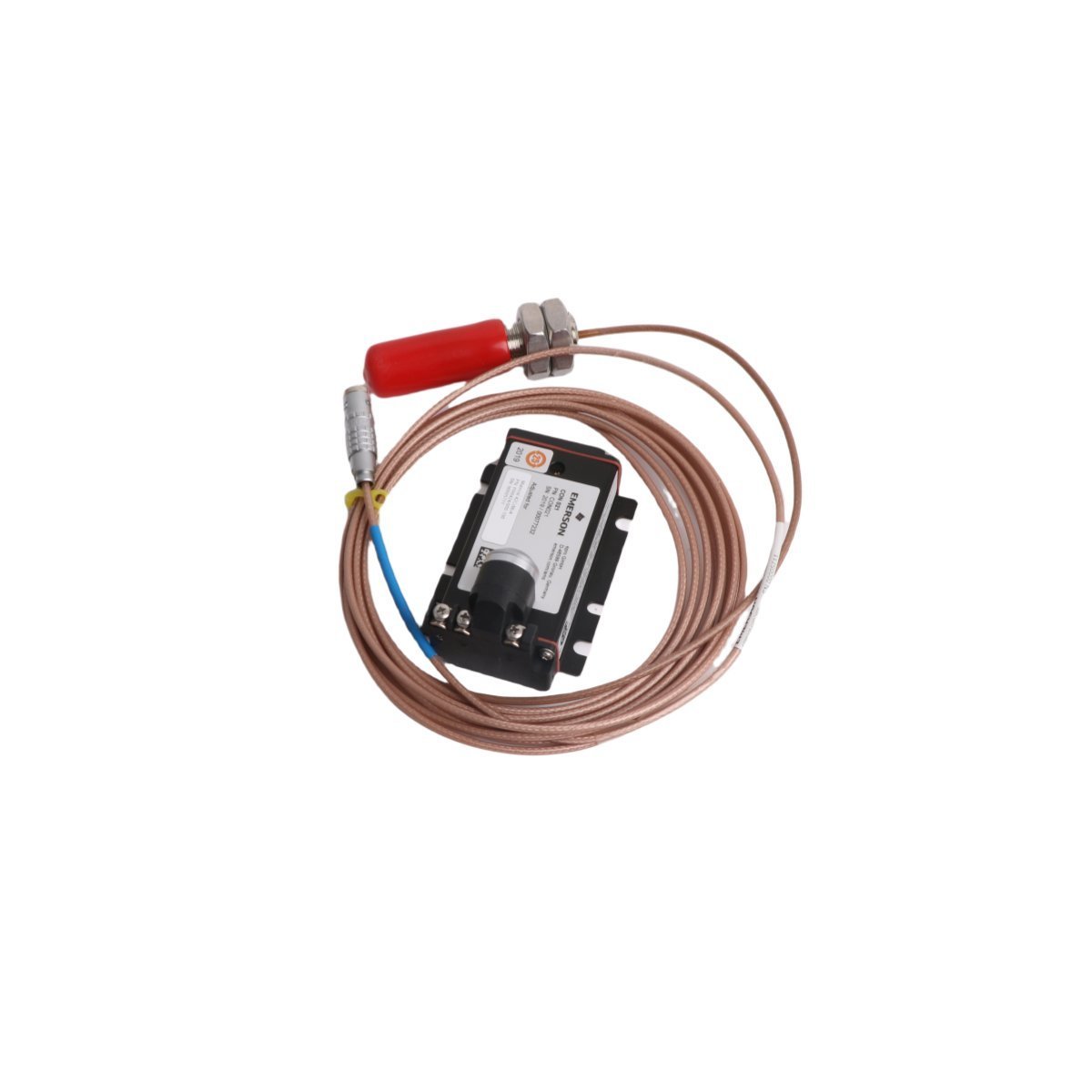
Emerson PR6423/010-130 CON021 Velocity Sensor
The Emerson PR6423/010-130 CON021, also cataloged as the PR6423/010-130 Velocity Sensor, operates as a dedicated hardware component for dynamic shaft vibration acquisition and position monitoring within EPRO machine monitoring systems.
Hardware Specifications
| Parameter | Specification |
|---|---|
| Model | PR6423/010-130 CON021 |
| Brand | Emerson |
| Product Range | EPRO |
| Module Type | Velocity Sensor |
| Origin | USA |
| Weight | 0.54 kg |
| Dimensions | 21 x 21 x 4 cm |
| Operating Temp | -35 to 180 deg C |
| Power Consumption | Passive sensor coil (driven by signal converter) |
| HS Code | 8537101190 |
| Lifecycle Status | Discontinued (Dec 31, 2018) |
Process Control and DCS Characteristics
- Converts magnetic field impedance changes into high-frequency analog signals proportional to target velocity and displacement.
- Interfaces with 4-20 mA HART loop protocol transmitters and DCS analog input cards for real-time monitoring.
- Ensures precise signal transfer using channel-to-channel isolation across multi-channel turbomachinery monitoring racks.
- Incorporates cold junction compensation (CJC) within matching signal conditioning units to mitigate temperature drift in industrial environments.
Frequently Asked Questions
Q: What function does the CON021 signal converter perform with the PR6423/010-130 probe?A: The CON021 signal conditioning unit provides the required high-frequency excitation current to the probe tip and converts raw impedance variations into calibrated voltage outputs.Q: How does mechanical clearance affect probe signal integrity?A: Unintended metal objects within the side clearance zone of the probe tip distort the electromagnetic field, requiring clear radial installation space around the target surface.Field Installation Guidelines
- Verify probe tip alignment and initial mechanical gap against the target face before applying system excitation power.
- Route signal interconnect cables through dedicated grounded steel conduit to suppress high-voltage electromagnetic interference.
- Maintain a minimum cable bending radius of 30 mm during field installation to avoid damaging internal conductor shielding.