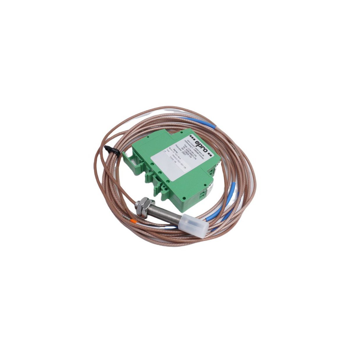
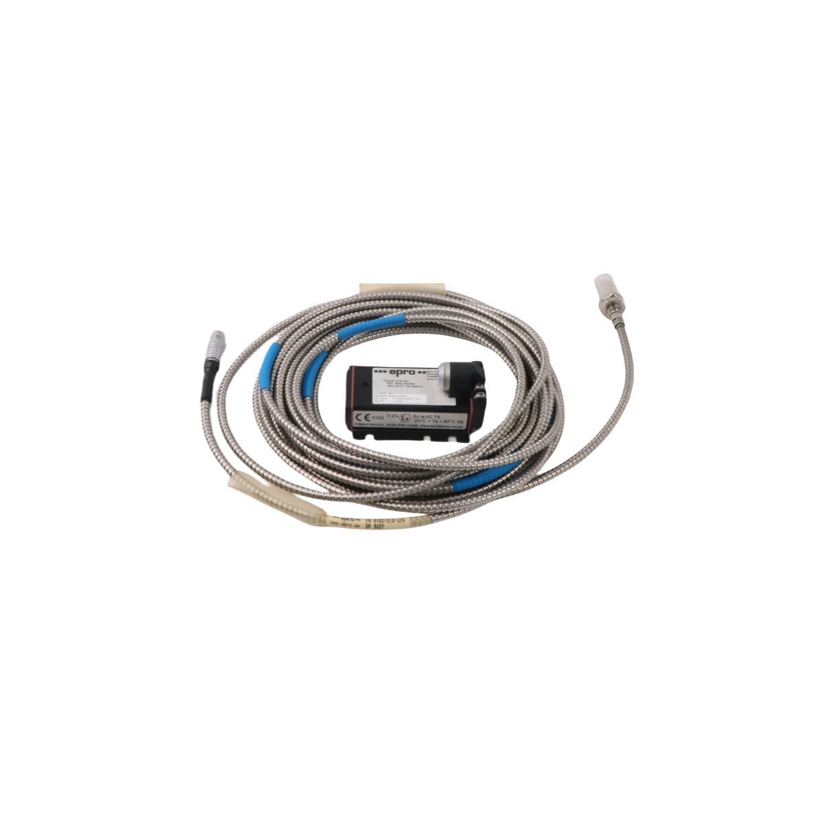
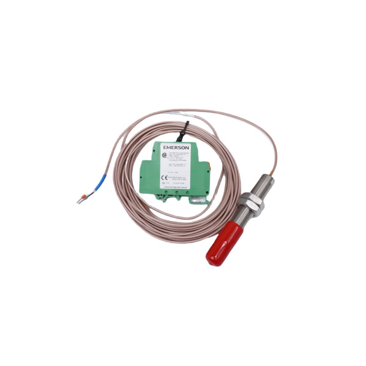
The EMERSON PR6423/010-010 CON021 is an industrial 8mm eddy current displacement probe engineered for critical machine vibration monitoring. Original factory surplus stock is available now with quick international shipping options. Maintain absolute machine protection and order your specialized replacement spares today.
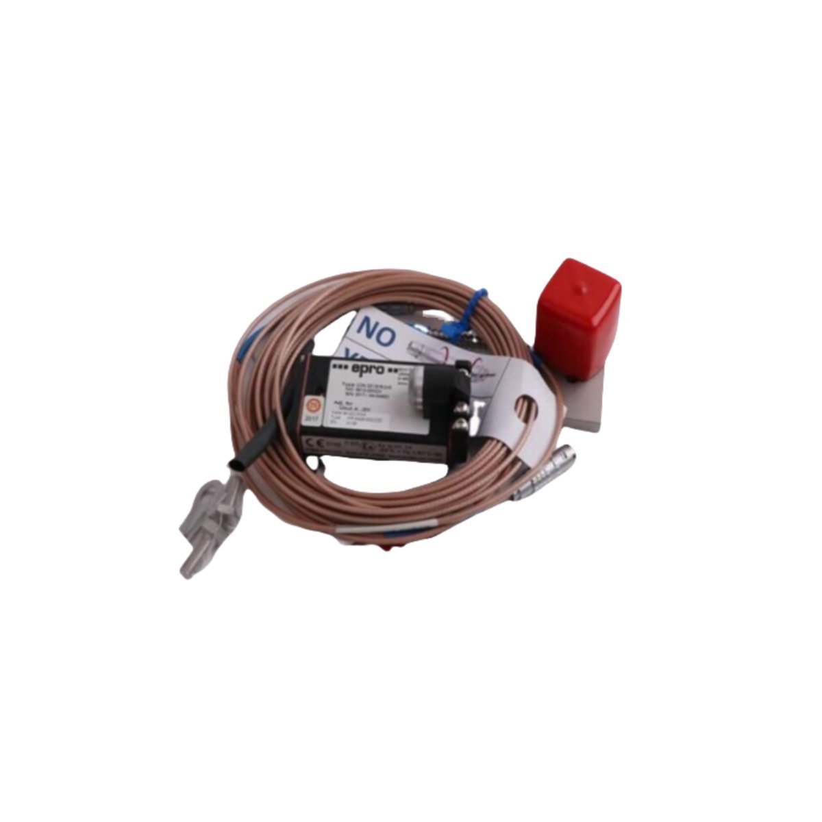
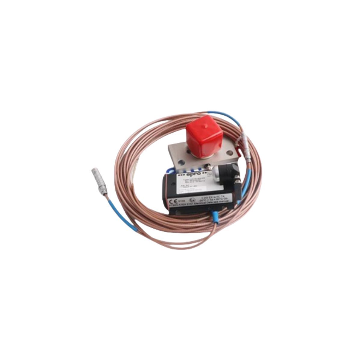
The EMERSON PR6423/010-010 CON021 is a high-precision EPRO Displacement Sensor (eddy current probe) engineered for non-contact shaft vibration, axial displacement, and eccentric position monitoring. Utilized within heavy machinery protection frameworks like the Emerson AMS 6500 / MMS 6000 machinery health systems, this sensor acts as a frontline data acquisition tool for critical rotating equipment.
Non-Contact Eddy Current Signal Processing & Vibration Monitoring
The sensor operates via the eddy current principle to measure the distance change between the probe tip and a moving ferromagnetic target surface (such as a turbine or compressor shaft). The probe tip houses an internally wound coil excited by a high-frequency RF signal delivered from an external driver module (converter/proximitor).
When a metallic target approaches the probe tip, eddy currents are induced on the surface of the target material, dampening the amplitude of the RF oscillation loop. This change is converted by the system into a precise, linear voltage or current loop proportional to the dynamic physical displacement. The high-quality design enables measurement resolution down to the micrometer level, allowing plant engineers to observe dangerous structural movements, dynamic shaft whip, or bearing wear patterns before mechanical breakdown occurs.
Frequently Asked Questions
Q: What does the suffix “CON021” signify on this specific assembly?
A: The “CON021” suffix denotes the integrated connector and cable layout configuration, typically specifying the length of the armored or unarmored extension lead and the presence of a waterproof LEMO or coaxial coupling tip.
Q: Can this probe connect directly to standard PLC analog input cards?
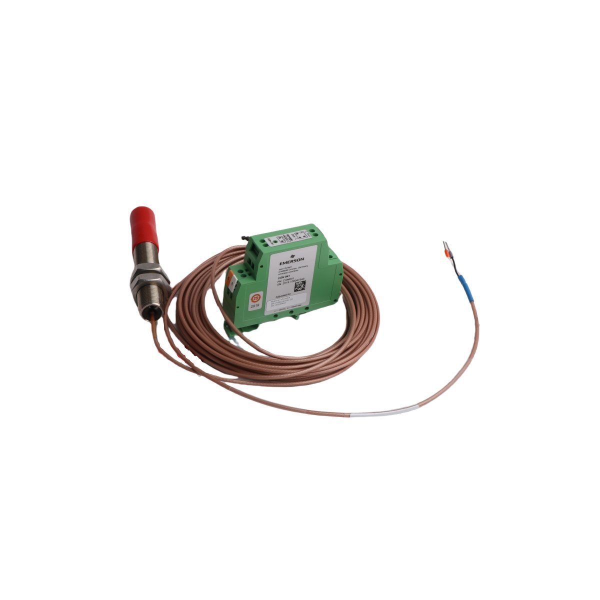
A: No. The raw sensor output requires an intermediary signal converter unit (such as a CON 021/011 driver or oscillator module). The driver converts the high-frequency probe impedance changes into a standard 4-20 mA loop or -10V to -24V DC signal suitable for PLC or DCS I/O racks.
Field Installation Guidelines
Target Material Calibration Check: Verify that the monitoring system driver is factory-calibrated for the specific shaft alloy composition (typically 4140 steel). Differences in metallurgy directly impact eddy current density and sensor scaling accuracy.
Mechanical Clearance Preset: Use a precise digital multimeter or thickness gauge to adjust the mechanical gap spacing during installation. Set the static probe distance to align with the center point of the linear voltage range (typically around -10 VDC).
Cable Bend Radius Controls: Maintain careful control when routing the sensitive coaxial extension lead. Avoid tight bends or pinching inside conduit boxes to prevent internal core reflections that create signal distortion.
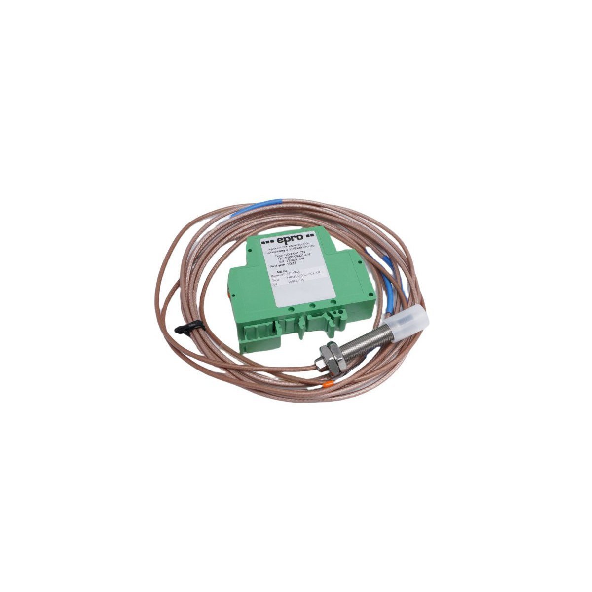
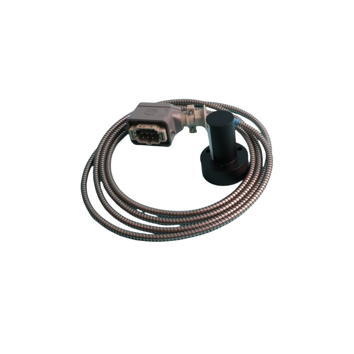
The EMERSON PR6423/002-001 CON041 operates as a high-precision non-contact eddy current sensor for critical industrial machinery monitoring. We offer this Brand New, original stock component with fast global shipping to prevent unexpected downtime. Secure this discontinued spare part for your system today.
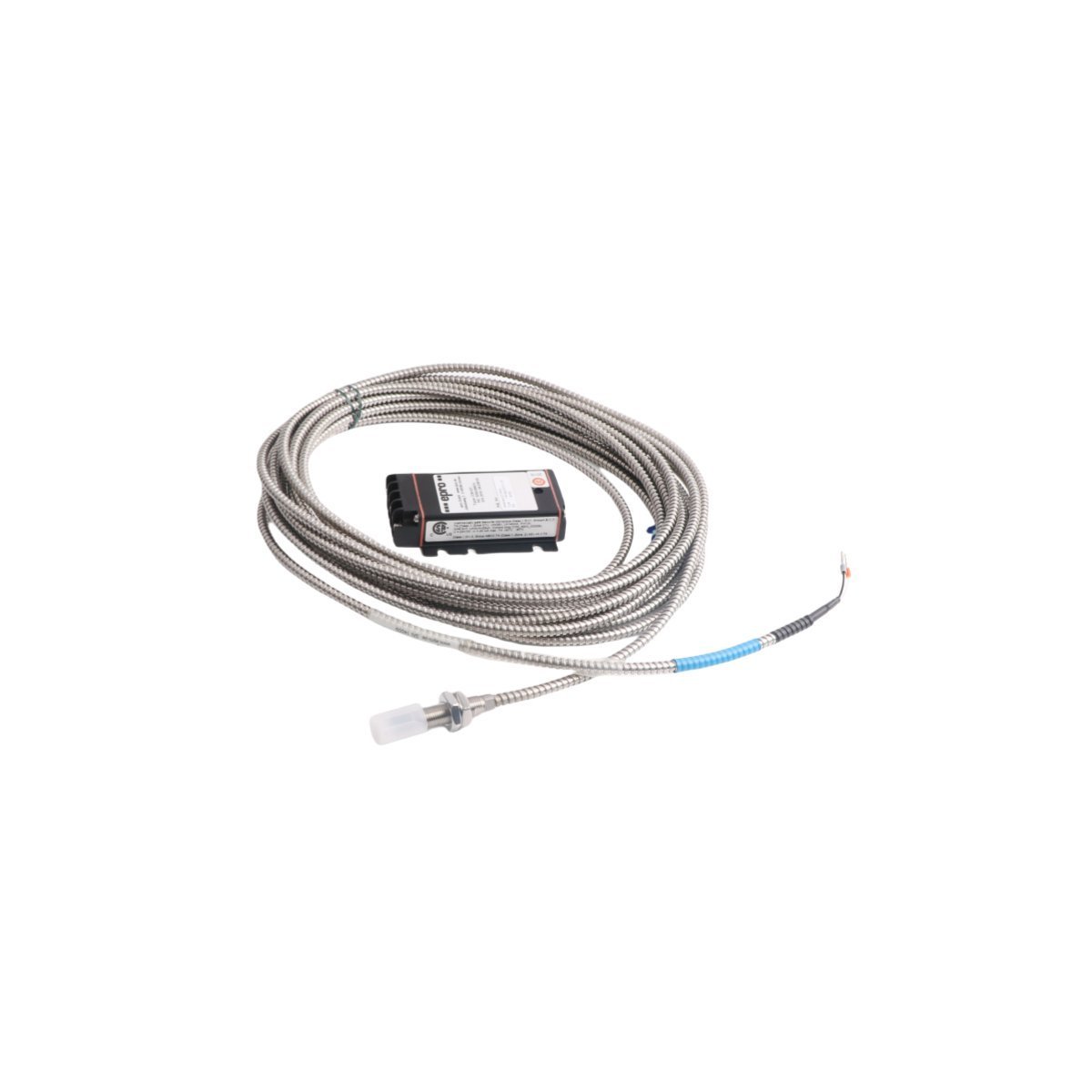
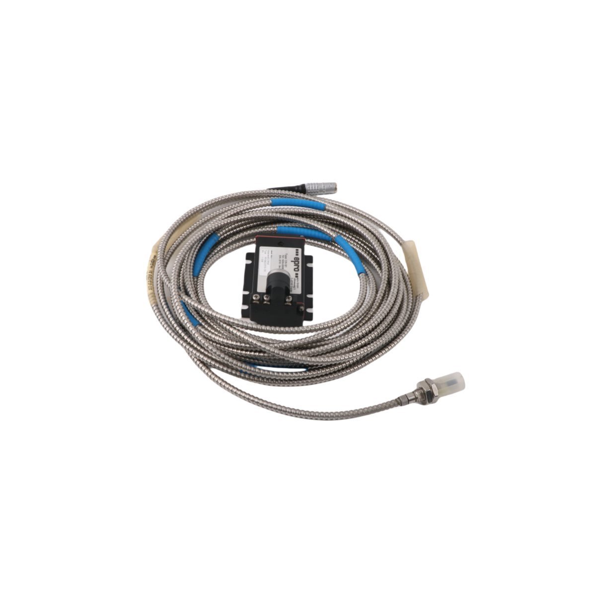
The EMERSON PR6423/011-131 is a high-precision 8mm non-contact eddy current proximity sensor for machinery health monitoring and shaft vibration analysis. Original factory surplus stock is ready to ship globally. Secure your critical turbomachinery asset protection hardware today.
The EMERSON PR6423/011-130 CON021 is a brand new, original stock eddy current sensor module. Global shipping is provided for this DCS and EPRO machinery protection component.
The EMERSON PR9268/017-100 is an electrodynamic seismic velocity sensor. Available as Brand New, Original Stock, with Global Shipping for asset protection.
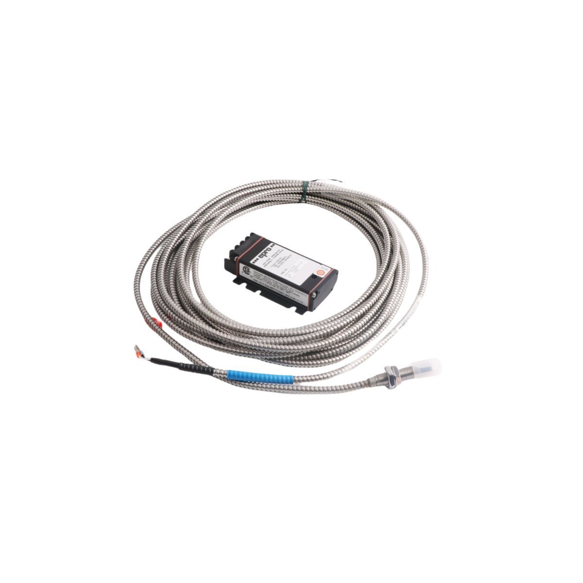
The Emerson PR6423/014-040 CON021 is an 8mm eddy current sensor for shaft vibration. It offers non-contact displacement monitoring for turbines and compressors in Epro systems.
The Emerson MMS6410 is a dual-channel measuring amplifier designed for inductive displacement sensors.It provides precise signal conditioning for turbines and compressors, supporting both static and dynamic physical measurements within the MMS 6000 system.
The Emerson PR6426/00-8M CON011 is a professional-grade 8-meter eddy current sensor designed for non-contact vibration and displacement monitoring. It provides high-precision data for turbines and compressors, ensuring machinery safety and enabling predictive maintenance through seamless DCS/PLC integration.
The Emerson PR6424/006-131 is an 8mm EPRO eddy current displacement sensor designed for non-contact vibration monitoring in rotating machinery. Featuring the CON041 converter, this industrial PLC module delivers high-precision signal acquisition and robust durability for critical asset protection and predictive maintenance.
The Emerson Epro PR9268/201-100 is a professional-grade electrodynamic velocity sensor for industrial vibration monitoring. This 1.22kg ruggedized module integrates seamlessly with Emerson DCS systems to provide accurate, real-time machinery health data, ensuring maximum uptime and proactive maintenance for rotating equipment.
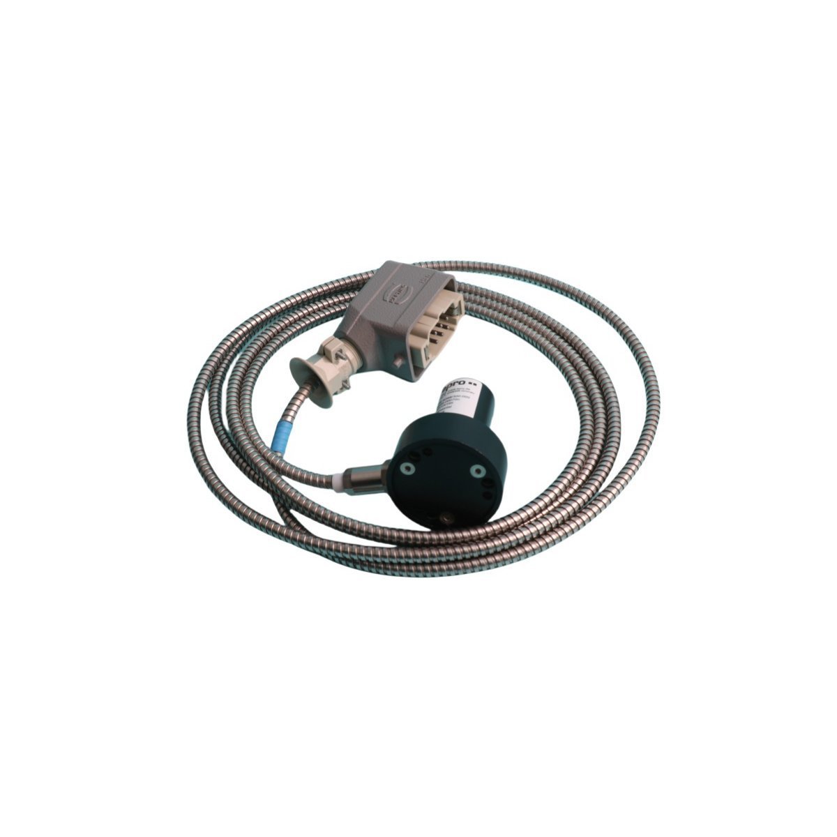
The Emerson EPRO PR6423/10R-141 CON031 is a professional 8mm non-contact eddy current sensor designed for industrial vibration and displacement monitoring. It offers high-precision measurement for rotating machinery, ensuring operational safety and enabling predictive maintenance in harsh environments.
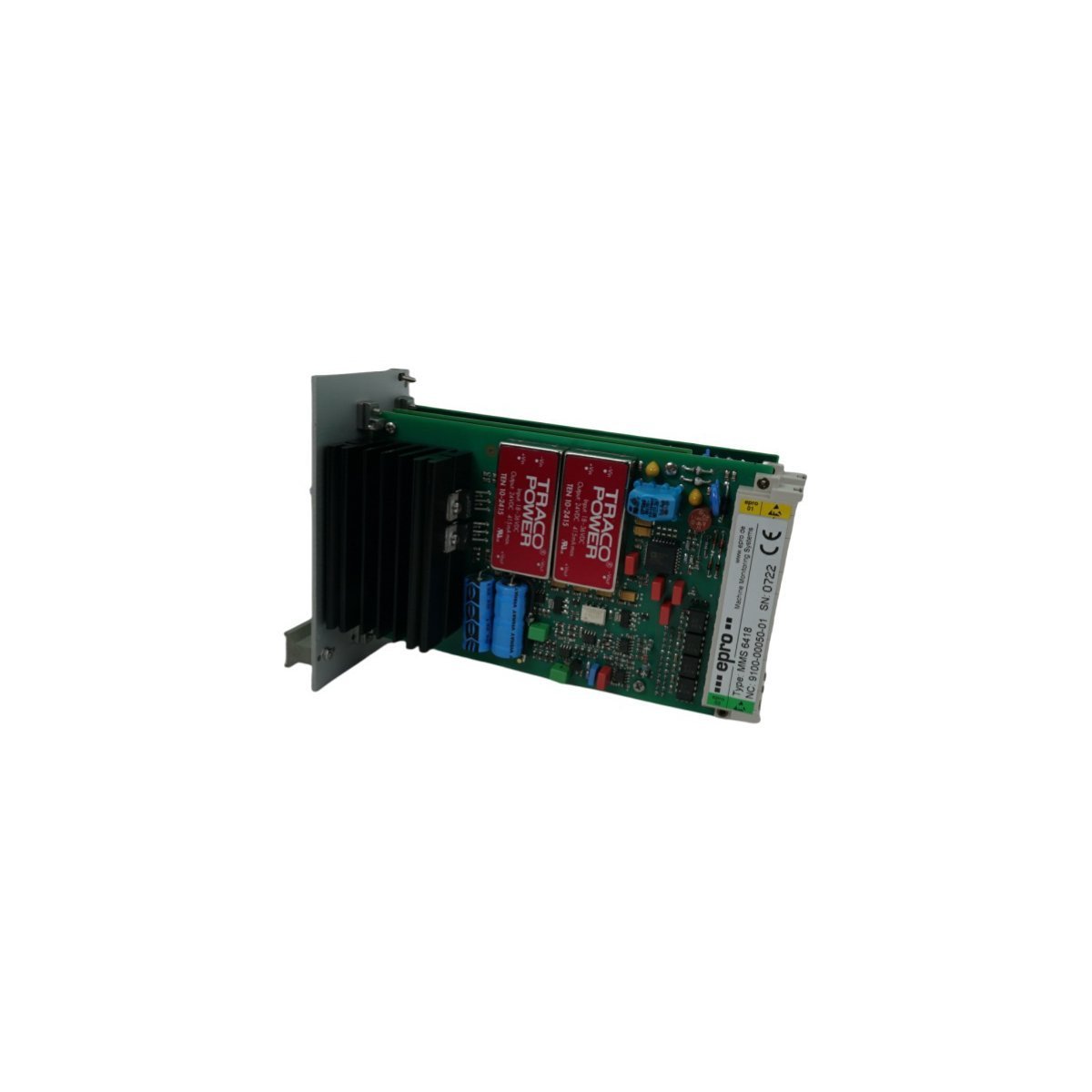
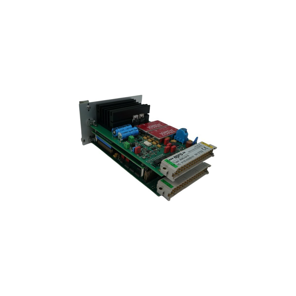
The Emerson MMS6418 is a professional Epro interface card designed for dual-channel shaft displacement and position monitoring. Integrated into the MMS6000 system, it provides high-accuracy vibration data and alarm protection for critical rotating assets like turbines and compressors.
The Emerson EPRO MMS6822 is a professional-grade interface monitoring card designed for the MMS6000 Machine Monitoring System. It provides high-speed Ethernet routing and data integration for real-time machinery protection, enabling predictive maintenance and advanced diagnostics for critical industrial assets.
We are committed to protecting your privacy. The information collected here is strictly used to provide the requested quotes, technical support, and relevant industrial automation solutions.