


Sale!
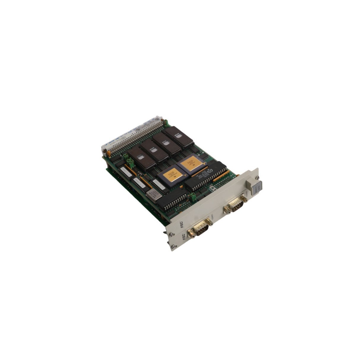

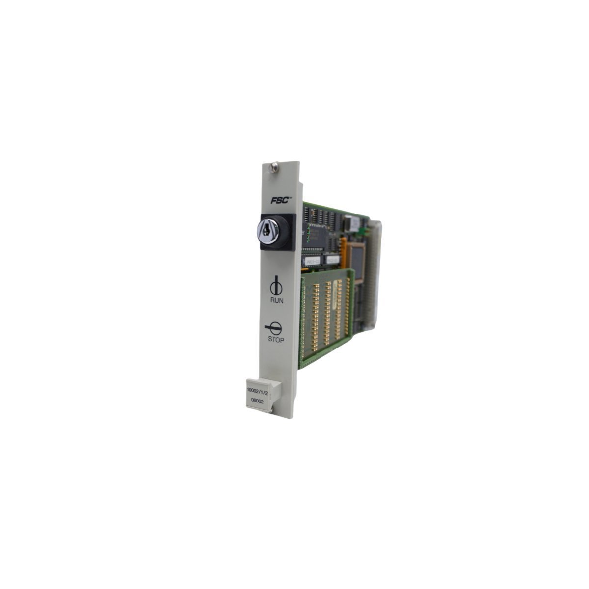
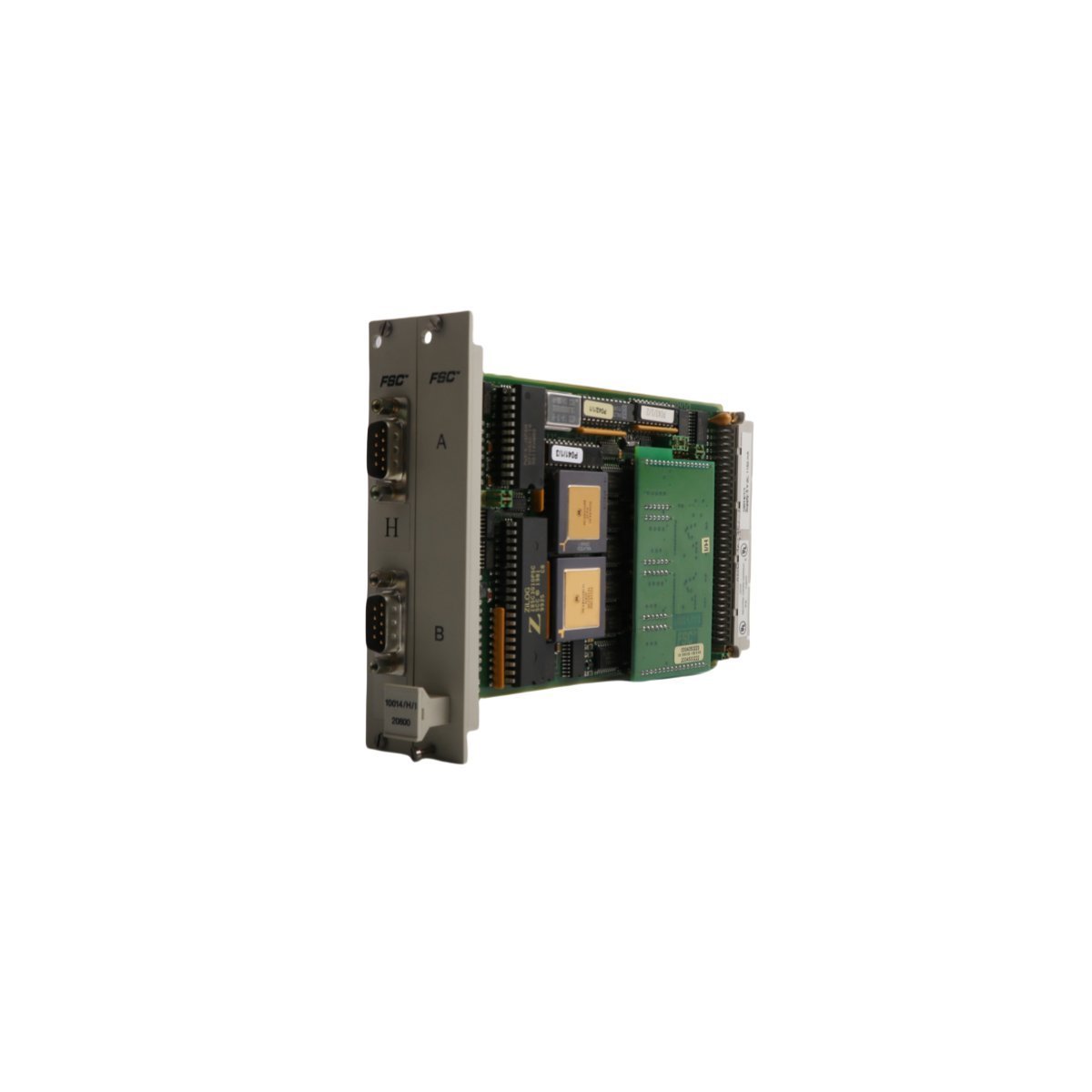
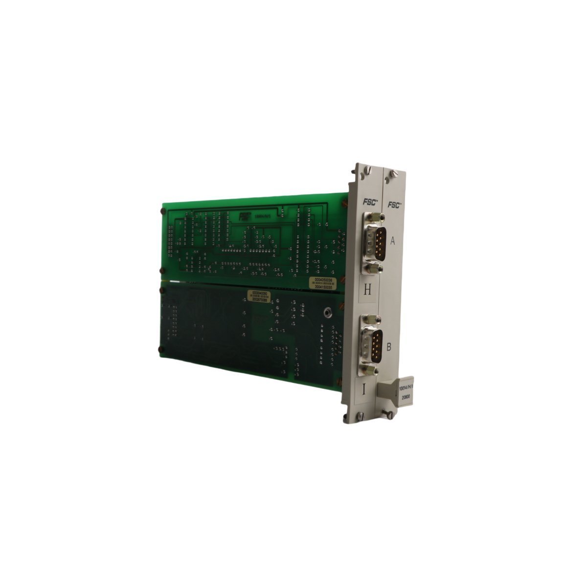
Honeywell 10004/1/1 FSC System Communication Module
Genuine Honeywell 10004/1/1 Communication Module for FSC System DCS environments. Brand new surplus, global delivery. Complete technical specifications and layout guidelines.
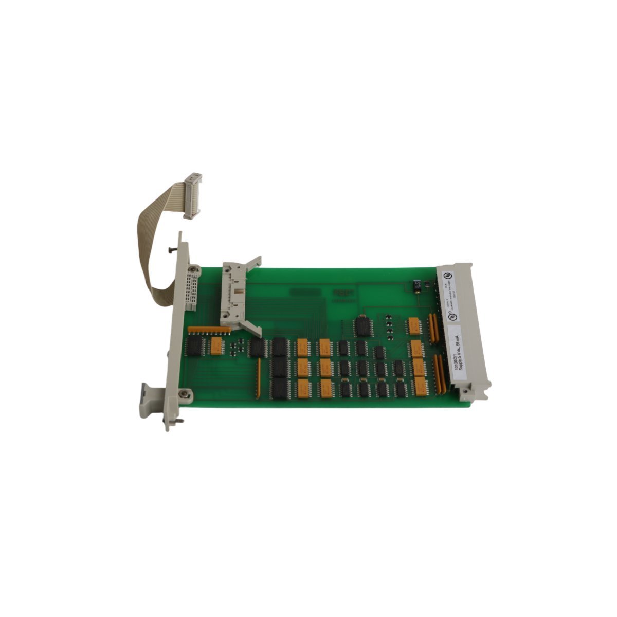
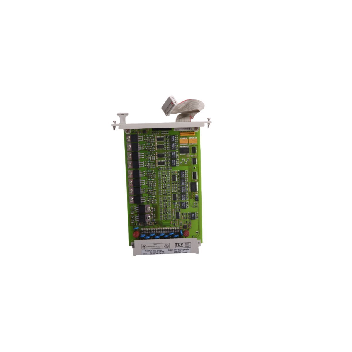
Order the HONEYWELL FC-SDOL-0424 V1.2 Safe Digital Output module. Available in Brand New, Original Stock with Global Shipping. Features integrated diagnostic tracking and internal diode suppression.
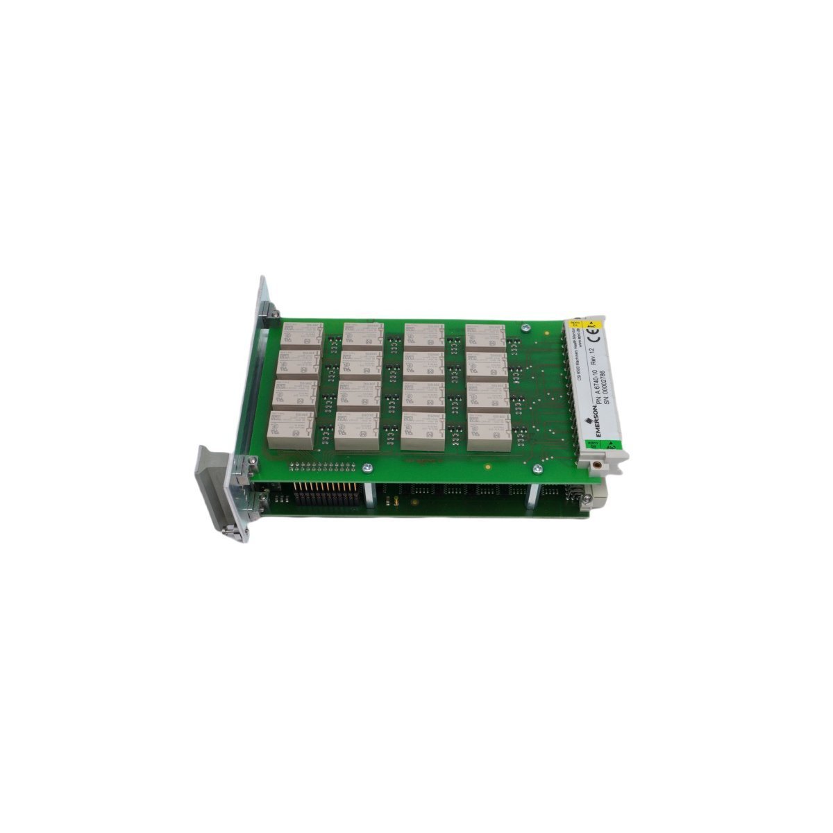
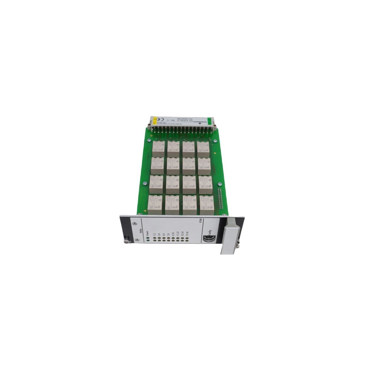
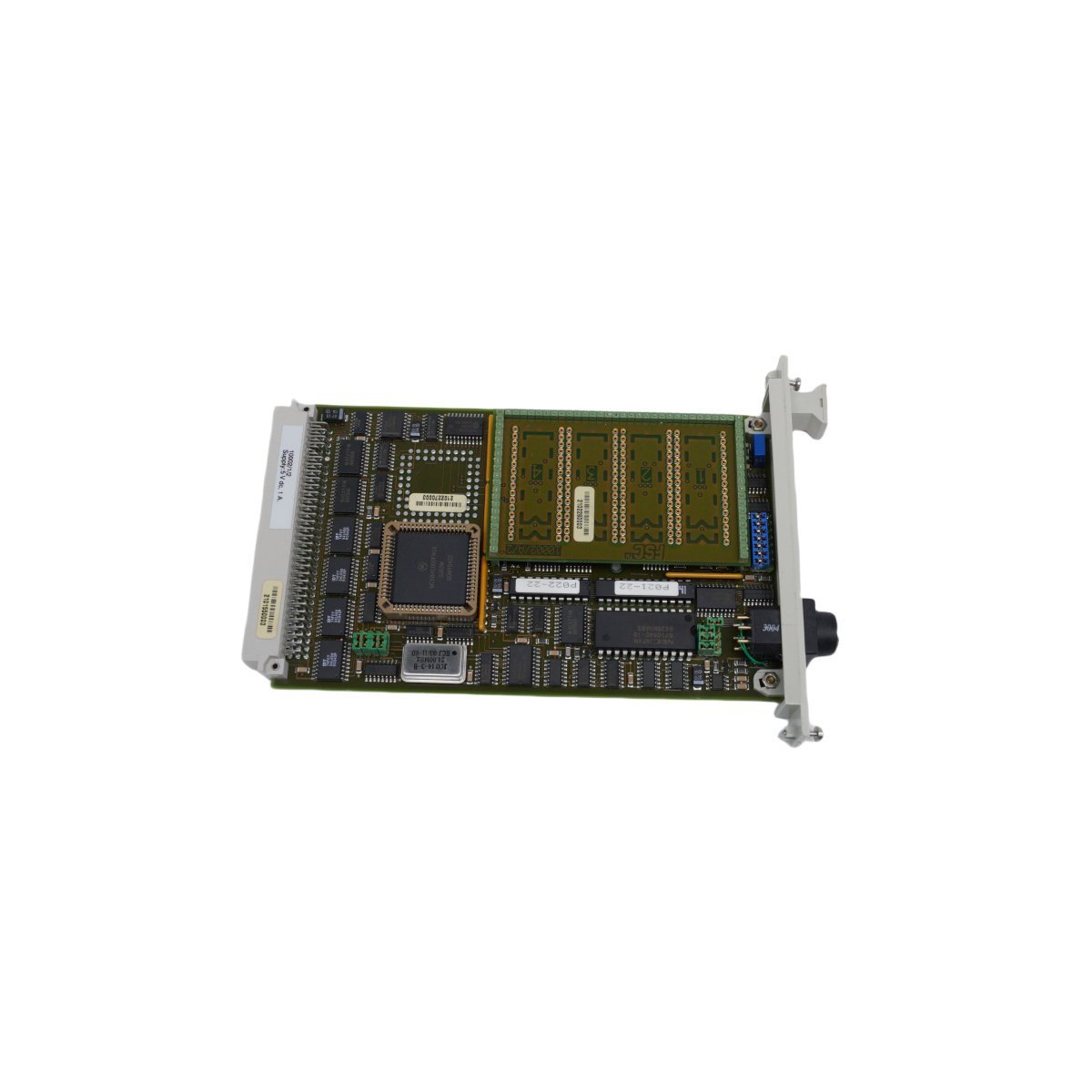
Configured for safe loop-monitored digital output execution in FSC System infrastructures, the HONEYWELL FC-SDOL-0424 V1.2 (FC-SDOL-0424 V1.2 PCB Board) provides direct physical/electrical execution. The hardware serves as an output driver interface, regulating and validating the power state of field-side inductive and resistive safety-critical components.
| Parameter | Specification |
|---|---|
| Model | FC-SDOL-0424 V1.2 |
| Brand | HONEYWELL |
| Origin | USA |
| Weight | 0.4 kg |
| Dimensions | 7 x 14 x 14.5 cm |
| Operating Temp | 0 to 60 deg C |
| Power Consumption | 24 VDC Loop Supply |
| Output Channels | 4 Independent Channels |
| Channel Rating | 24 VDC @ 1 A per channel |
| Max Module Load | 3.6 A total |
| Diagnostics | Lead breakage, short-circuit, cross-talk validation |
| Internal Protection | Integrated inductive load suppression diodes |
| HS Code | 8537101190 |
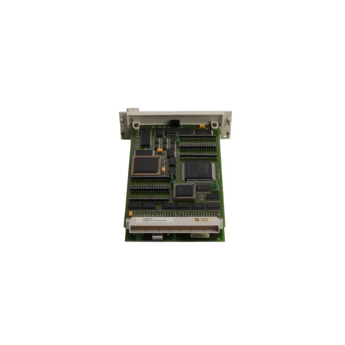
The HONEYWELL FC-SDOL-0424 V1.2 incorporates specialized 4-20 mA HART loop protocol elements and discrete monitoring matrices to sustain SIL-rated loop tracking. The module enforces galvanic isolation parameters across internal system-side microprocessors and external 24 VDC fields. Built-in circuitry runs continuous pulse testing to verify fail-safe de-energization loops without disrupting active field actuators. Dual-path isolation barriers prevent potential ground offsets from shifting control metrics, while automated cross-talk suppression verifies channel-to-channel isolation under maximum current conditions.
Q: How does the FC-SDOL-0424 V1.2 manage the diagnostic pulse testing without tripping active safety relays?
A: The onboard processing firmware issues narrow sub-millisecond diagnostic pulses to check line continuity and short-circuit conditions. These pulses do not contain sufficient energy to cause field relays or inductive solenoid coils to drop out or change status.
Q: Is external diode suppression needed when driving heavy inductive industrial valves?
A: No. Every channel on the board contains integrated, hardware-validated suppression diodes matched to the 1 A current limits. This design handles the inductive inductive back-EMF natively during de-energization phases.
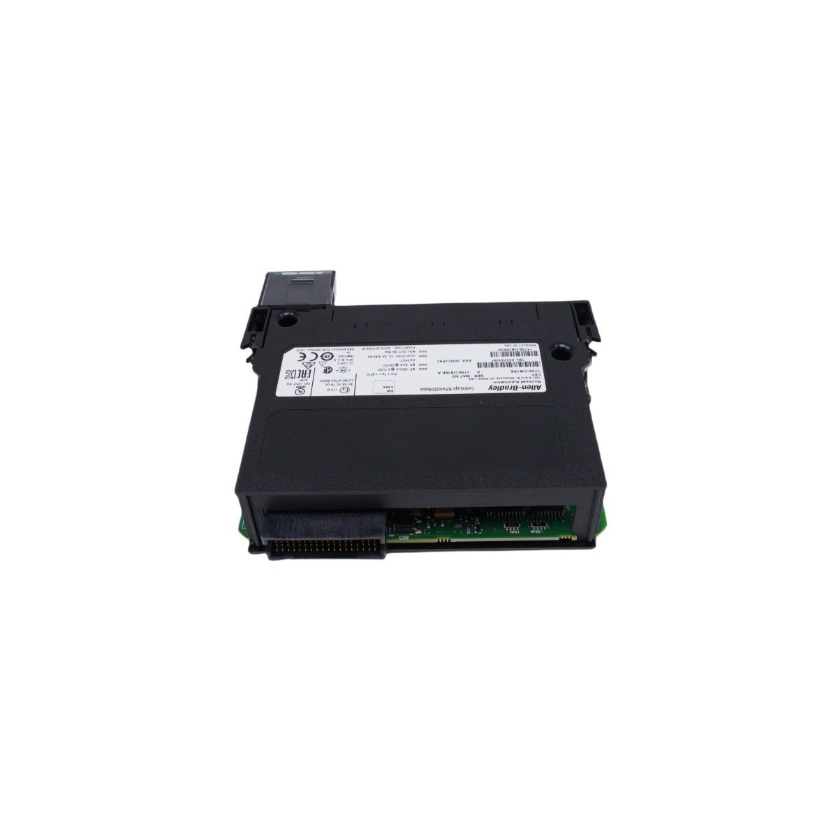
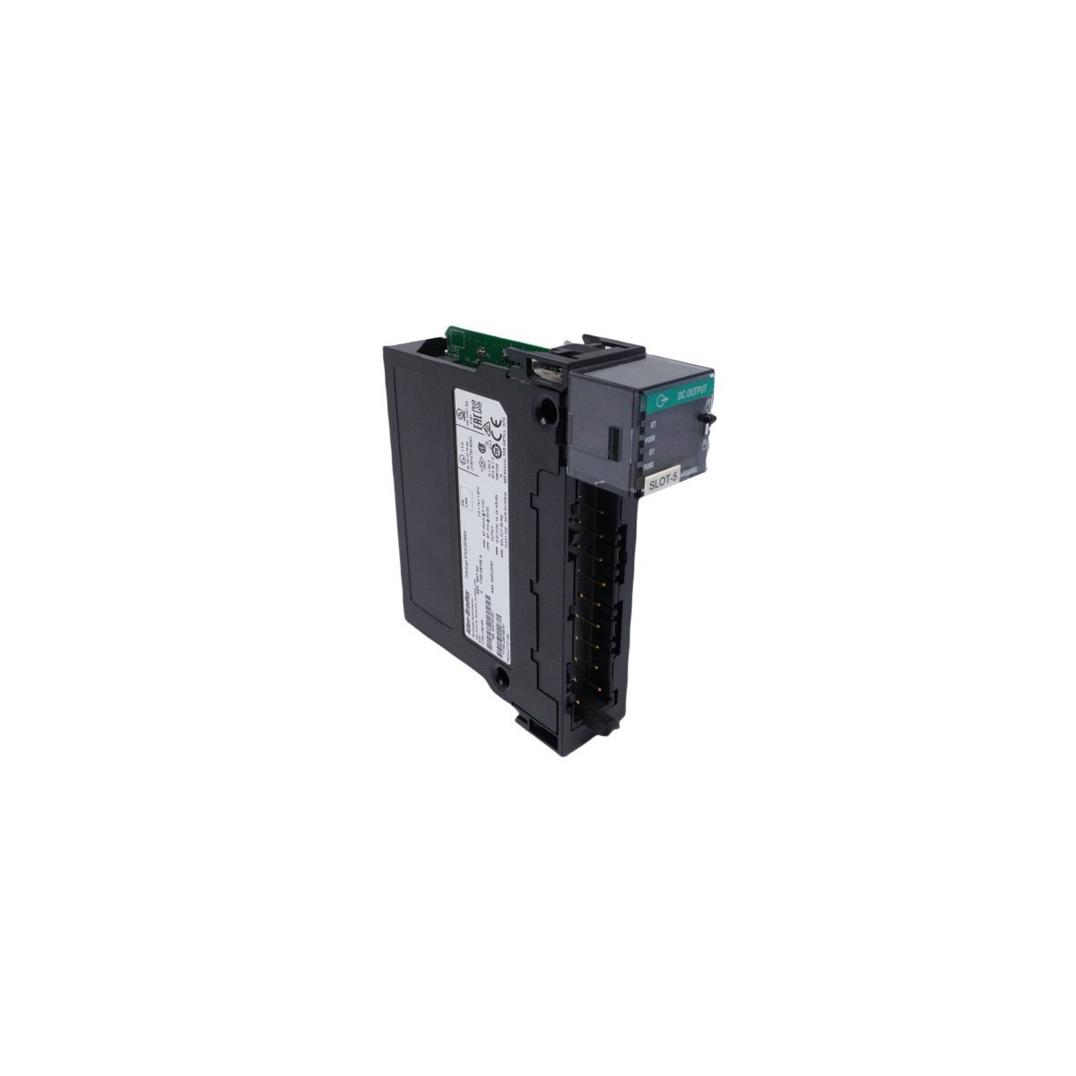
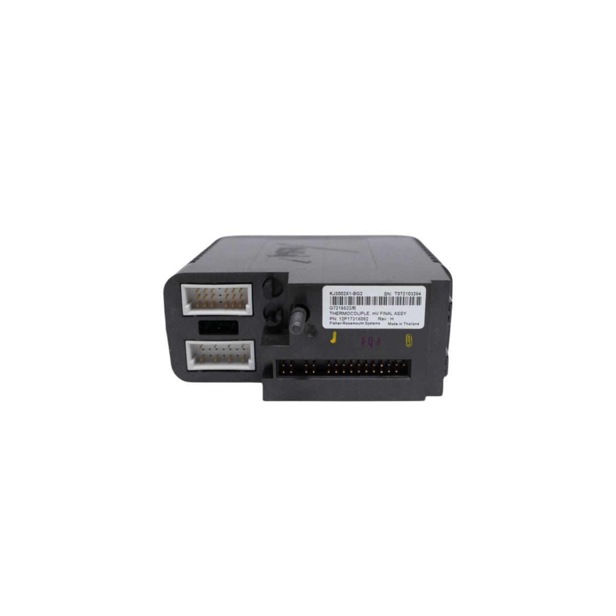
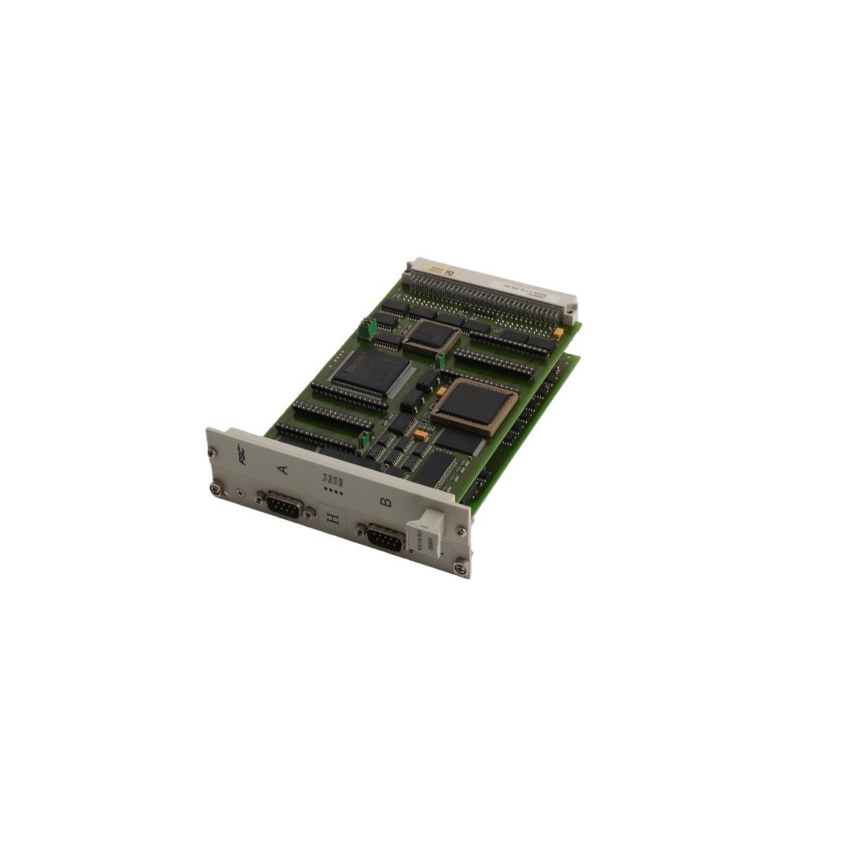
The Emerson DeltaV™ M-series KJ3002X1-BB1 (12P0683X092 / VE3006) is a legacy, high-precision thermocouple and mixed-signal I/O module designed for flexible process control within the DeltaV Distributed Control System (DCS). Capable of reading continuous analog variables alongside discrete status indicators, this modular card features built-in galvanic signal isolation, advanced thermocouple loop-burnout diagnostics, and high-density noise protection. Engineered for direct hot-swappable installation into M-series carriers, it delivers stable, industrial-grade data acquisition for critical temperature, flow, and pressure monitoring loops across harsh, high-interference manufacturing environments.


We are committed to protecting your privacy. The information collected here is strictly used to provide the requested quotes, technical support, and relevant industrial automation solutions.