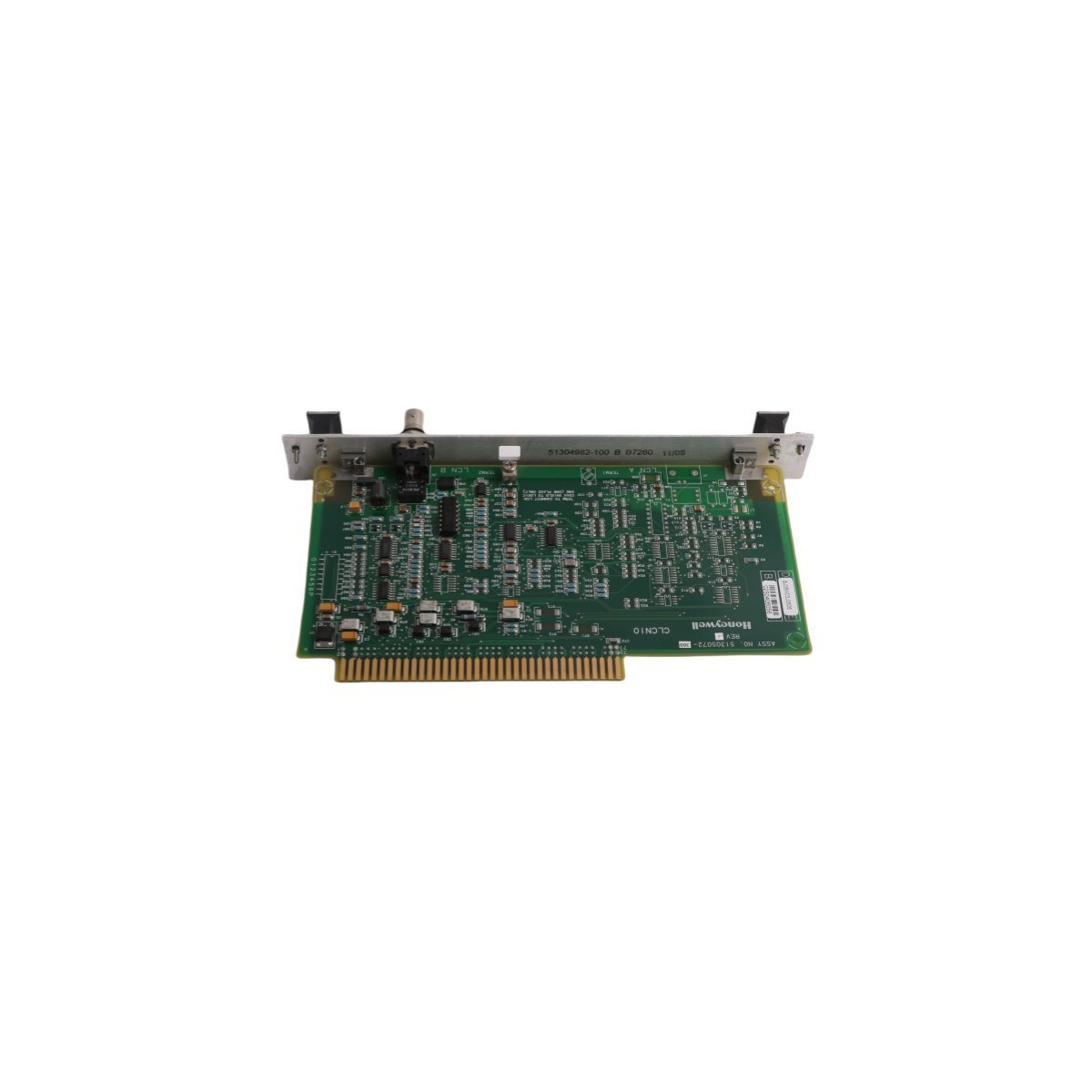
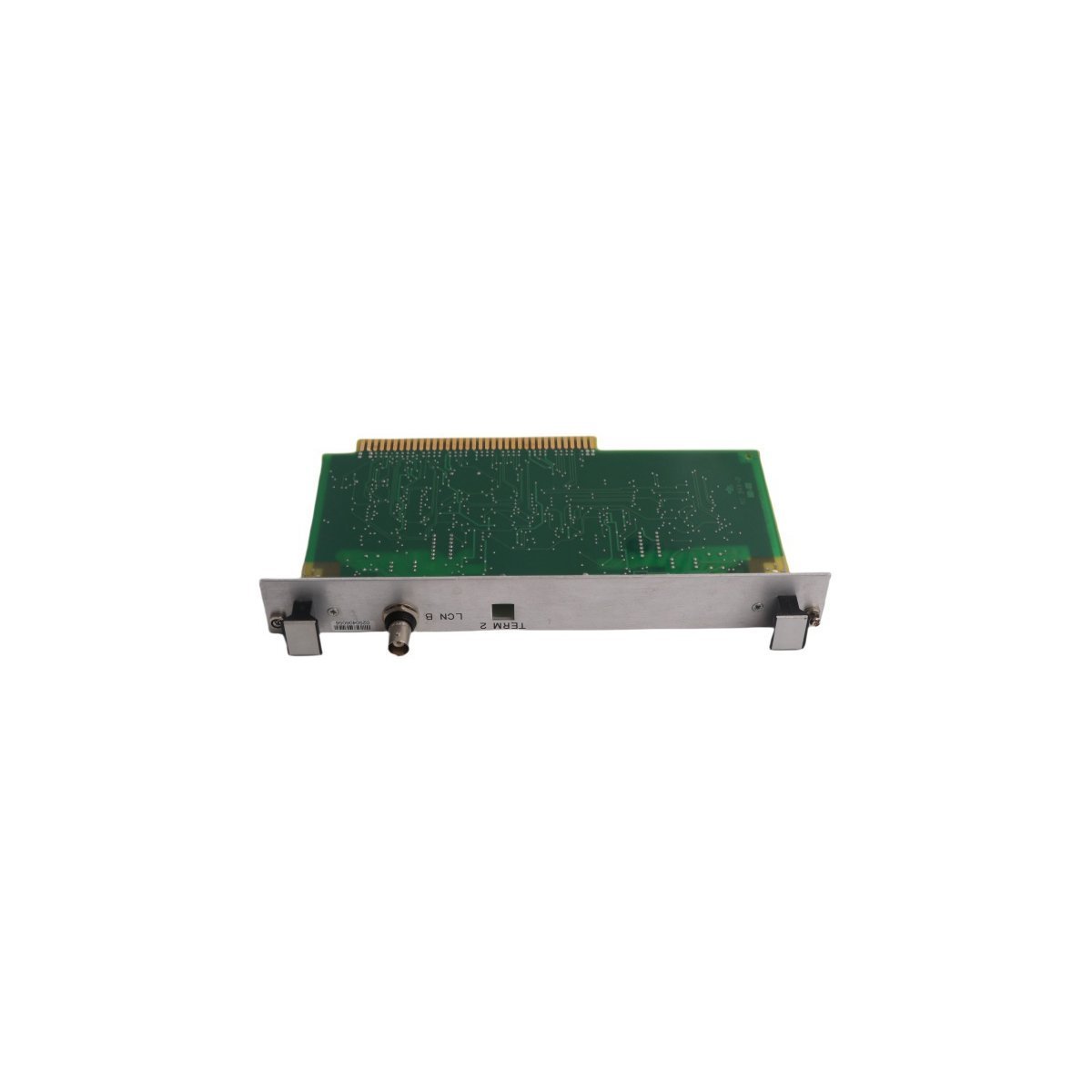
Sale!
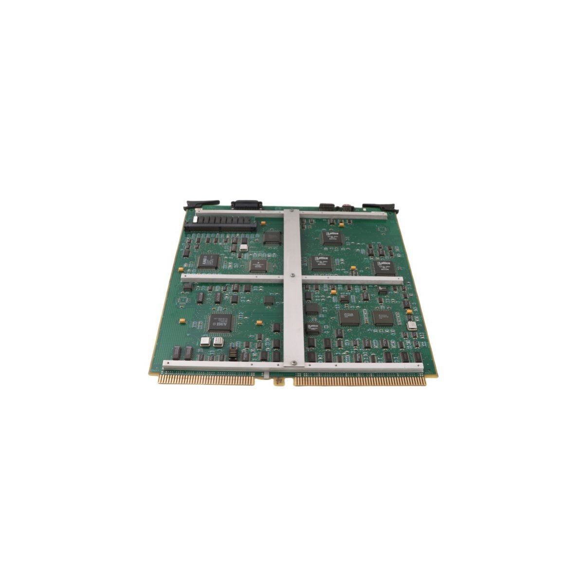
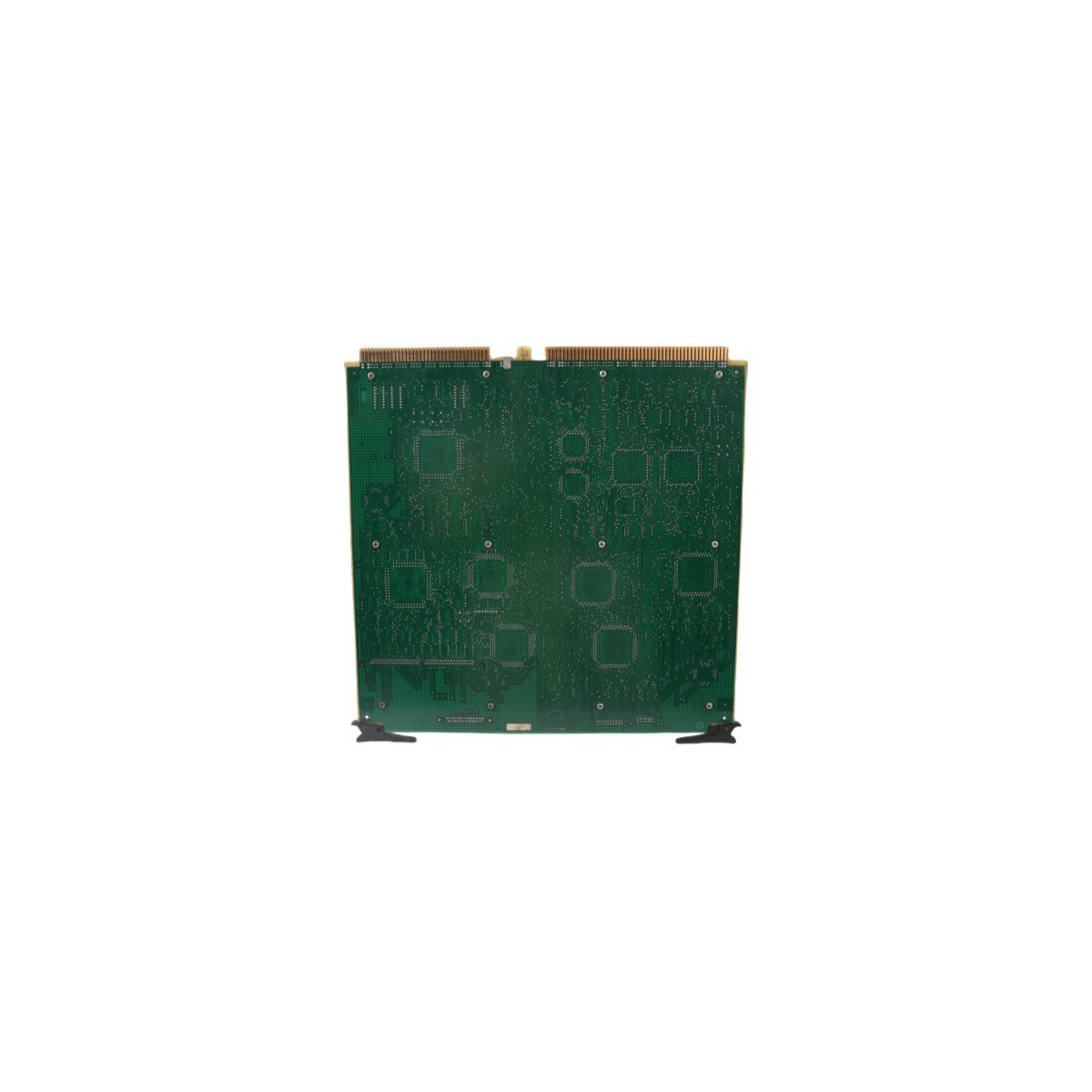
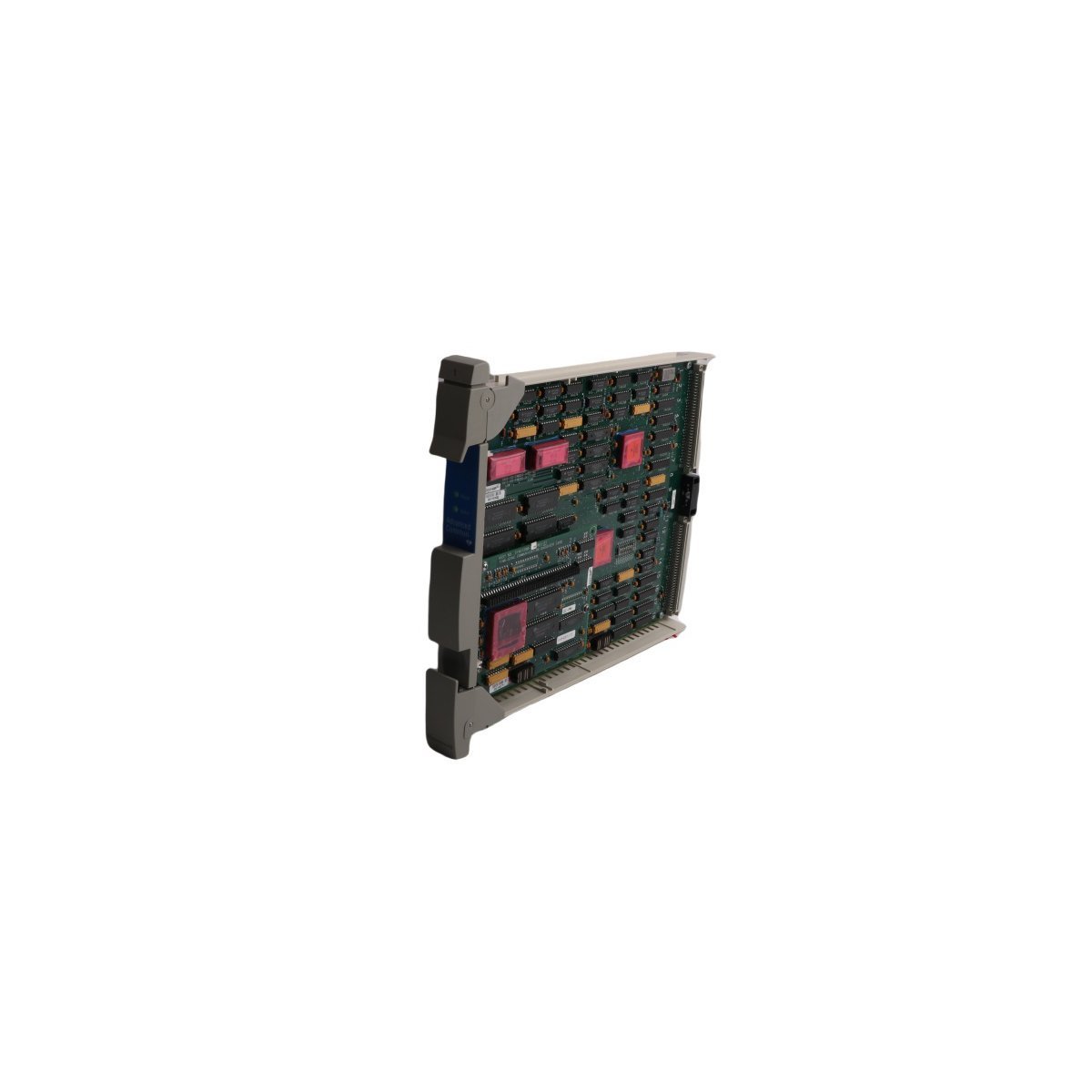
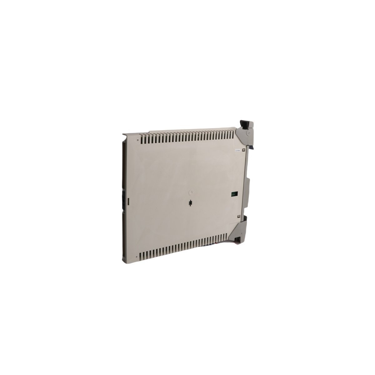
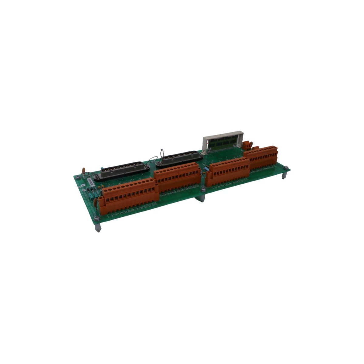
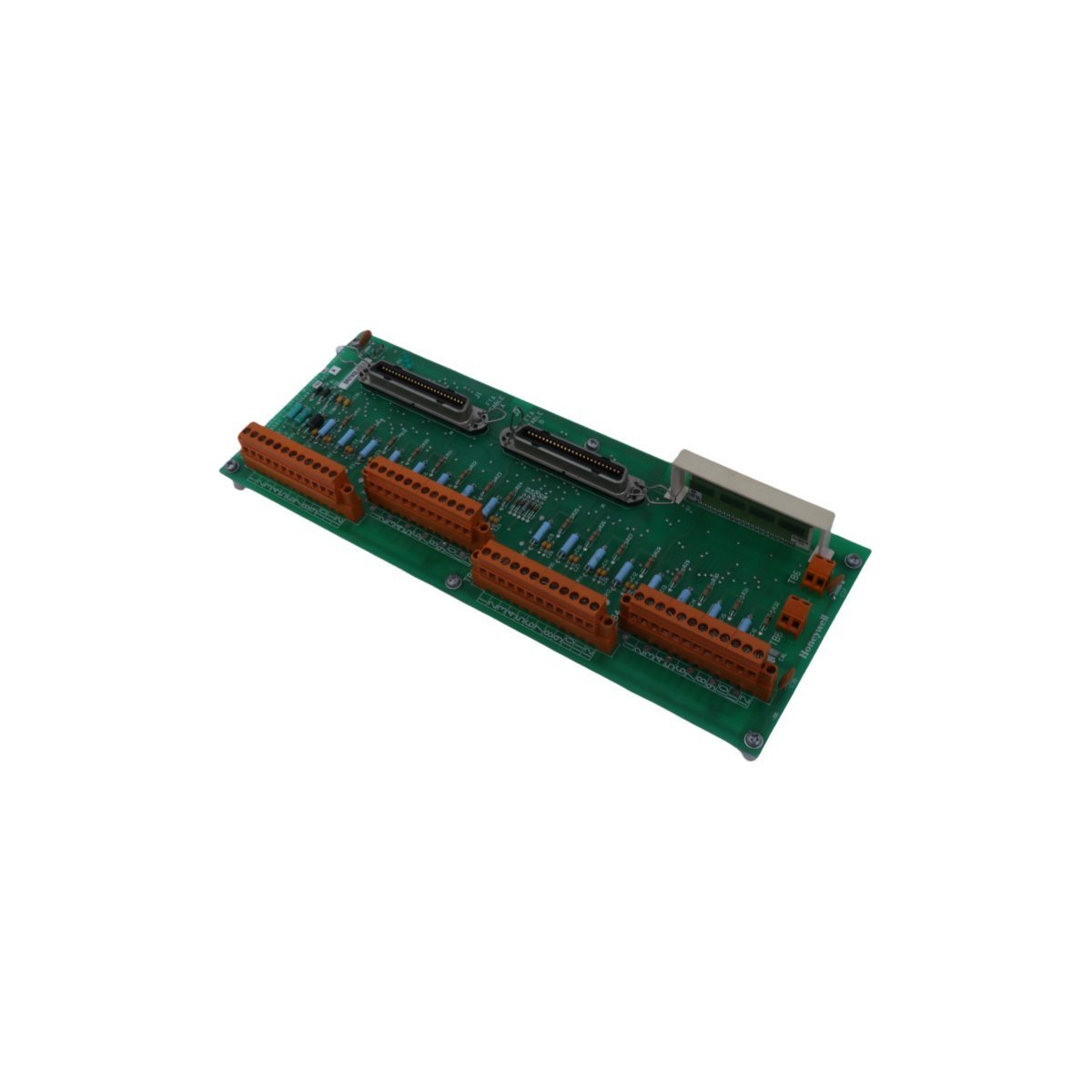
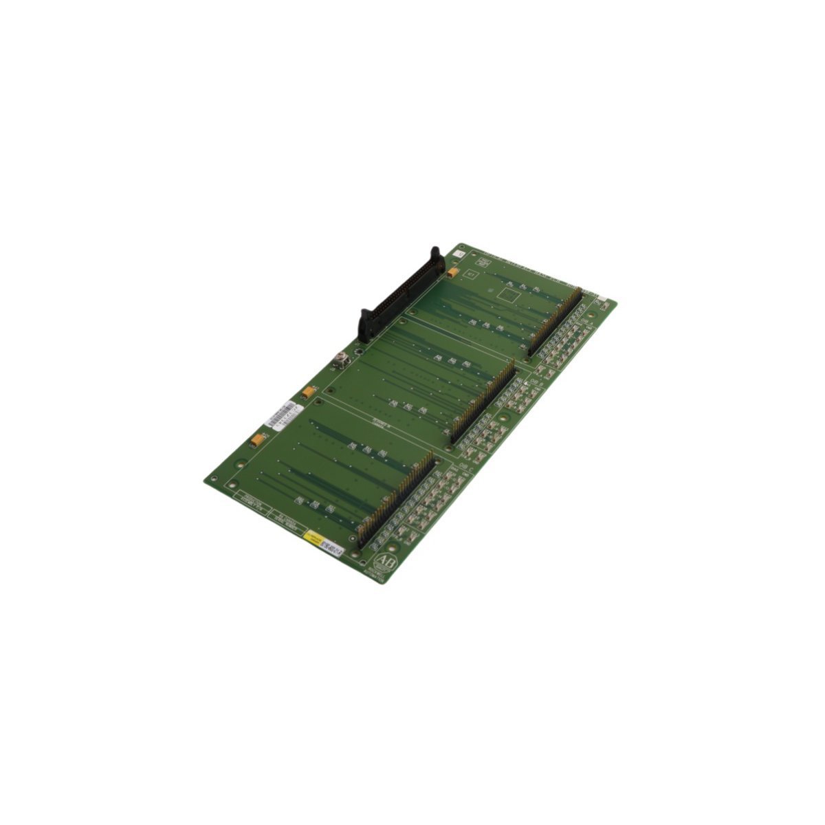
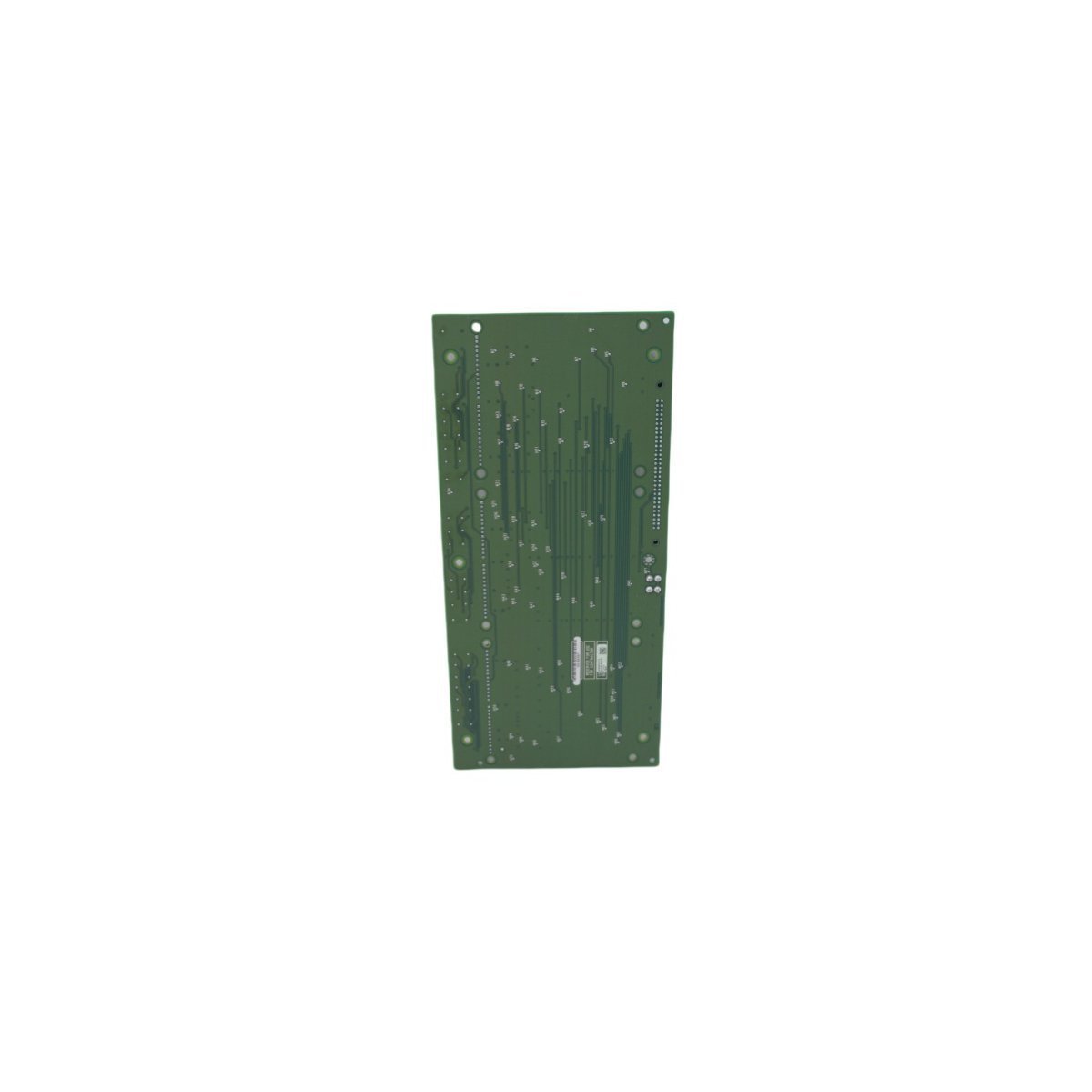
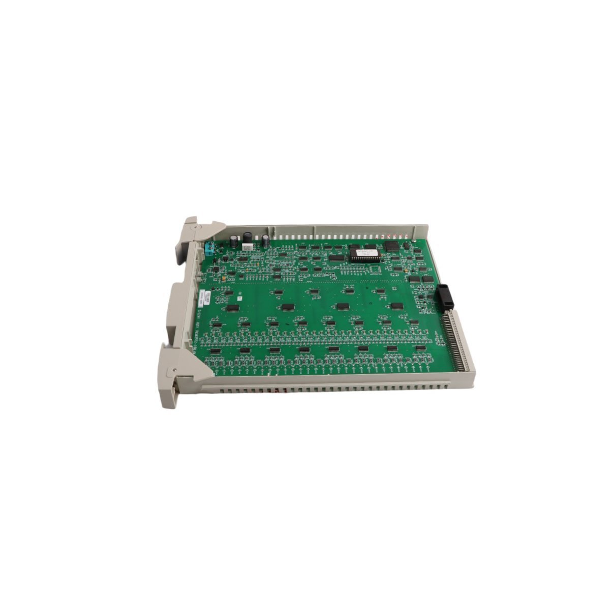
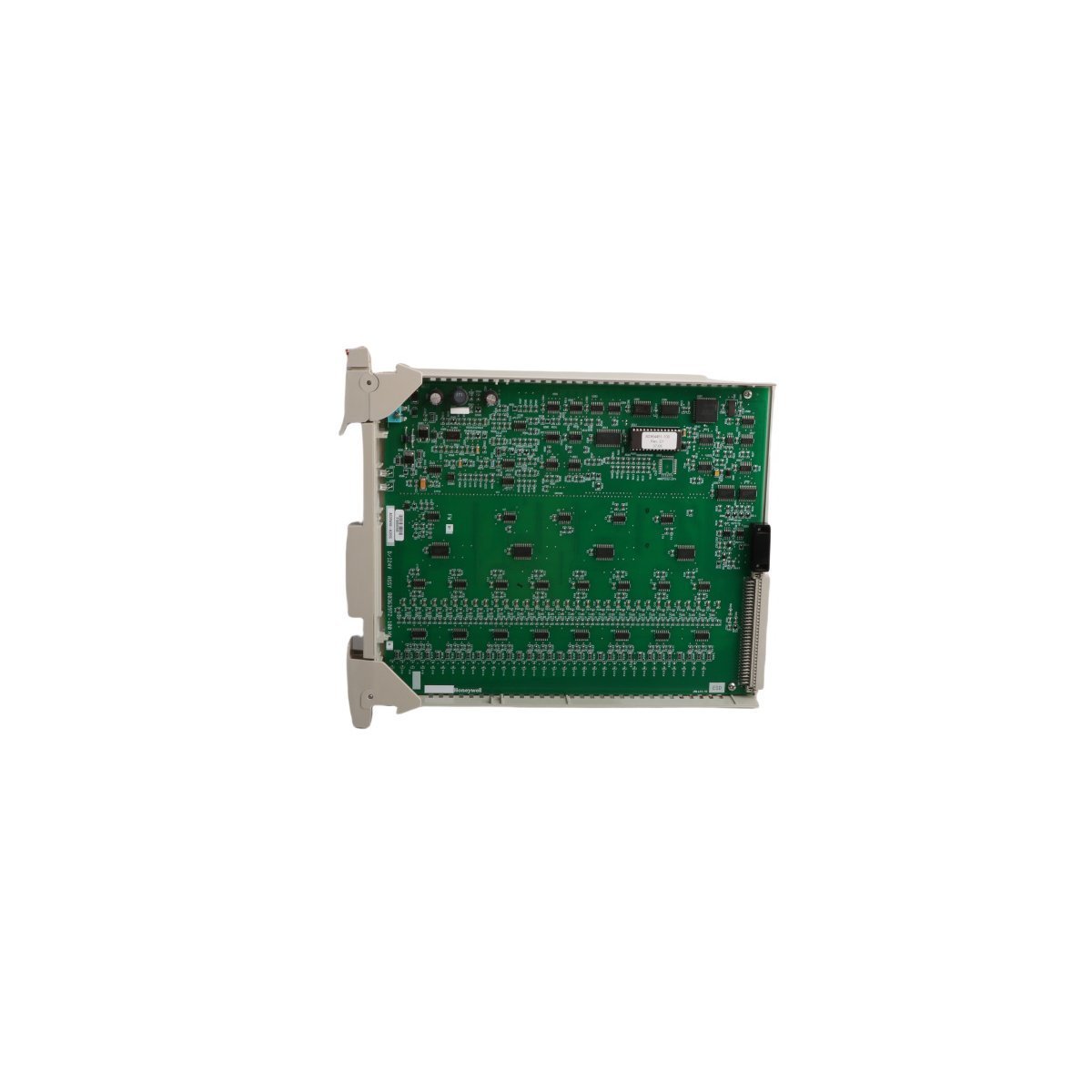
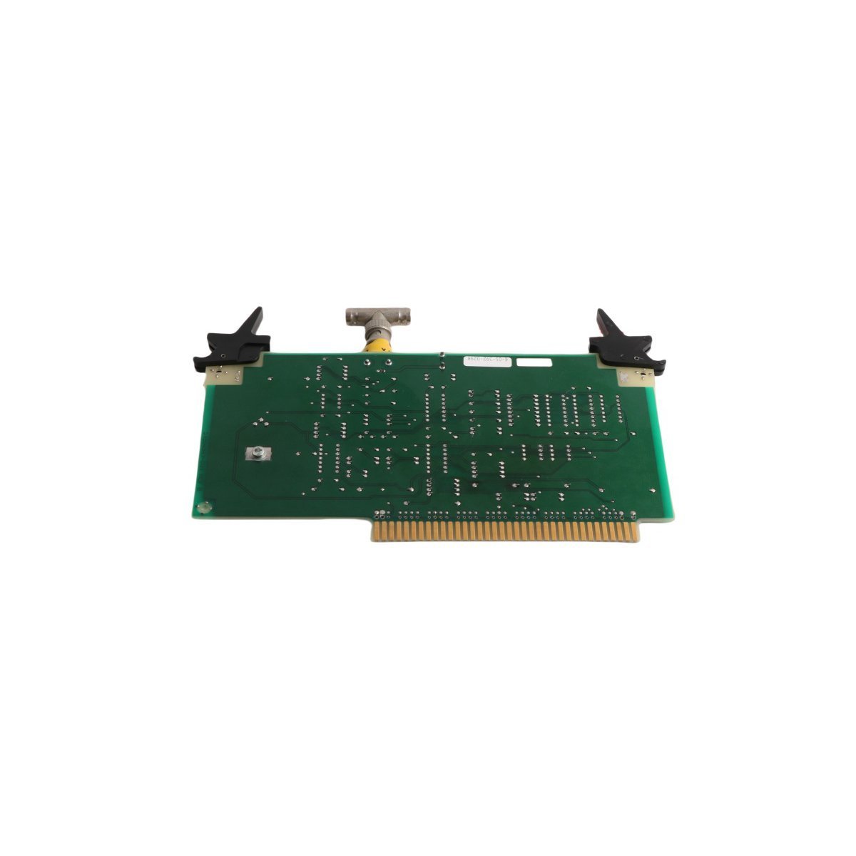
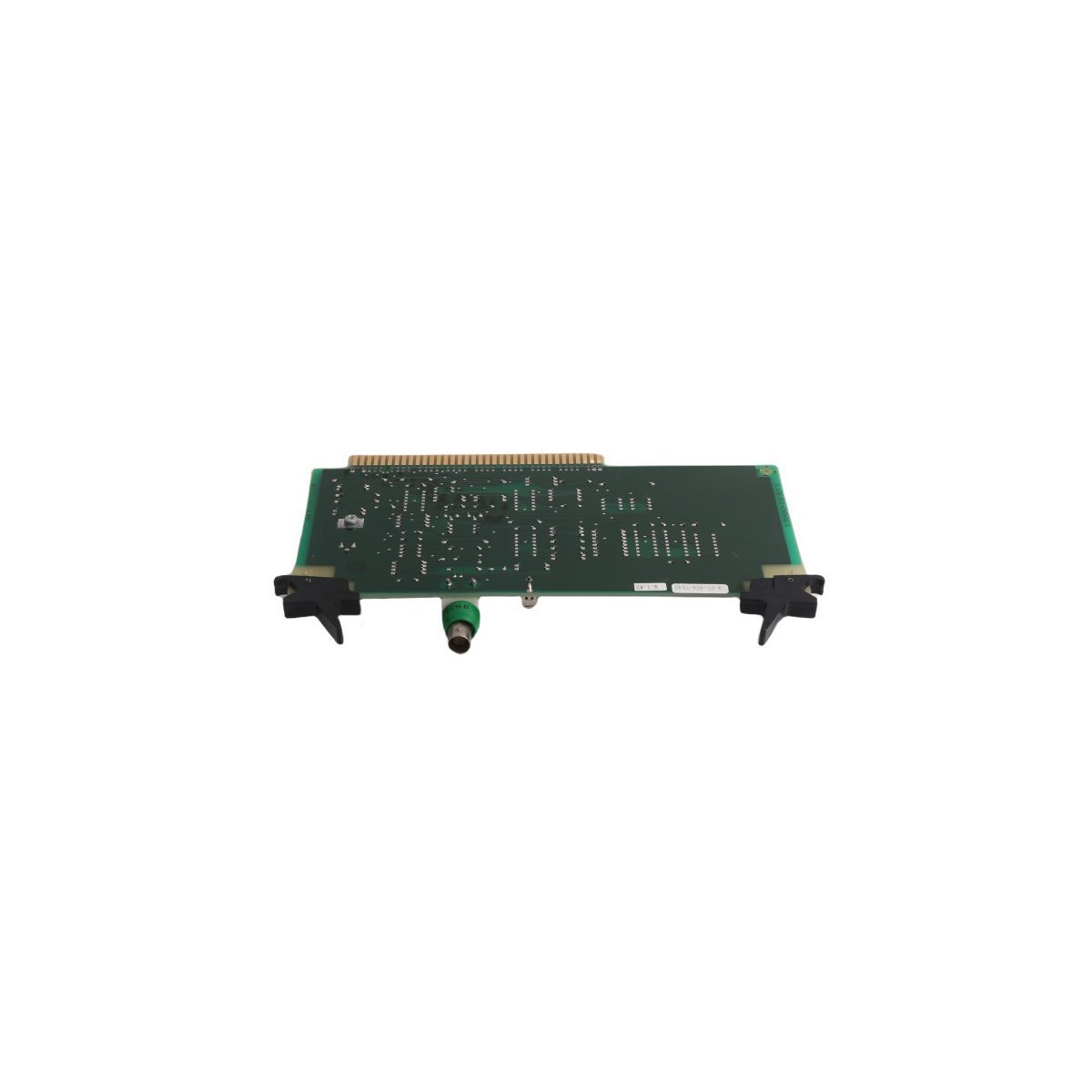
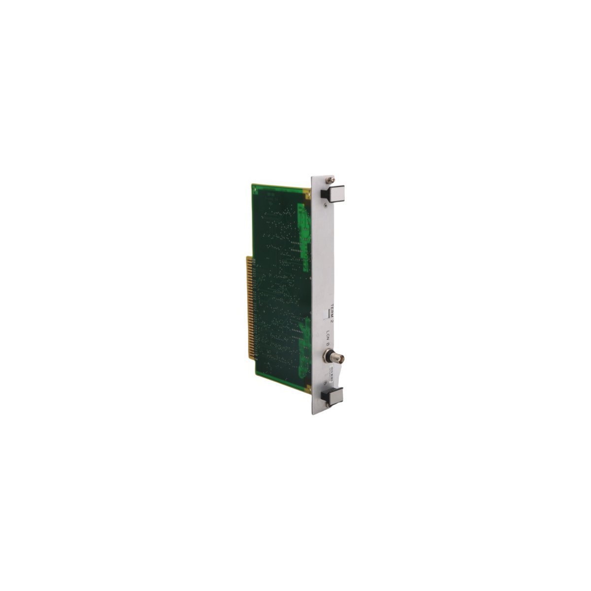
Honeywell K2LCN-4 51402615-400 TDC 3000 PCB Card
- Configured for local control network routing and high-density memory processing in Honeywell TDC 3000 DCS node chassis, the Honeywell K2LCN-4 51402615-400 (K2LCN-4 PCB Card) provides direct physical/electrical execution. It handles real-time node interaction and high-speed data transfer across the local control network infrastructure, serving as an integrated local control network board configured with 4 megawords of onboard memory.
Hardware Specifications
Parameter Specification Model K2LCN-4 51402615-400 Brand Honeywell Origin USA Weight 0.92 kg Dimensions 36.6 x 36.3 x 2 cm Operating Temp 0 to 60 deg C Power Consumption Standard TDC 3000 Backplane Power Module Type PCB Card System TDC 3000 DCS Memory Capacity 4 Megawords Communication Service Ethernet / LCN Router Board HS Code 8537101190 Process Control & Channel Isolation
The Honeywell K2LCN-4 51402615-400 integrates within the TDC 3000 backplane to facilitate deterministic channel-to-channel communication across industrial process networks. Utilizing onboard memory capacity combined with dedicated transceiver paths, the assembly supports 4-20 mA HART loop protocol routing and multi-node synchronization while maintaining galvanic separation to suppress electrical noise and ground loops across node drops.Frequently Asked Questions
Q: What is the primary function of the 4 megawords memory allocation on the board?A: The onboard 4 megawords memory provides local storage for execution code, communication buffer queues, and network state management required for real-time node routing within the Local Control Network (LCN).Q: Can the K2LCN-4 card be inserted while the node chassis is powered?A: Insertion or removal must follow Honeywell TDC 3000 maintenance procedures. Power down the card slot or rack segment prior to removal to prevent transient current surges on the backplane bus.Field Installation Guidelines
- Ensure main chassis power is disconnected before sliding the module into the designated TDC 3000 card cage slot.
- Align the board edges strictly with the card cage guide rails to prevent mechanical pin bending on the rear connector matrix.
- Apply firm, even pressure on the card edge ejector levers until the board seats fully into the backplane socket.
- Fasten all retention screws to secure chassis grounding continuity and mechanical stability under vibration.
- Verify shield ground terminations on external communication cables to maintain proper channel-to-channel isolation and noise immunity.