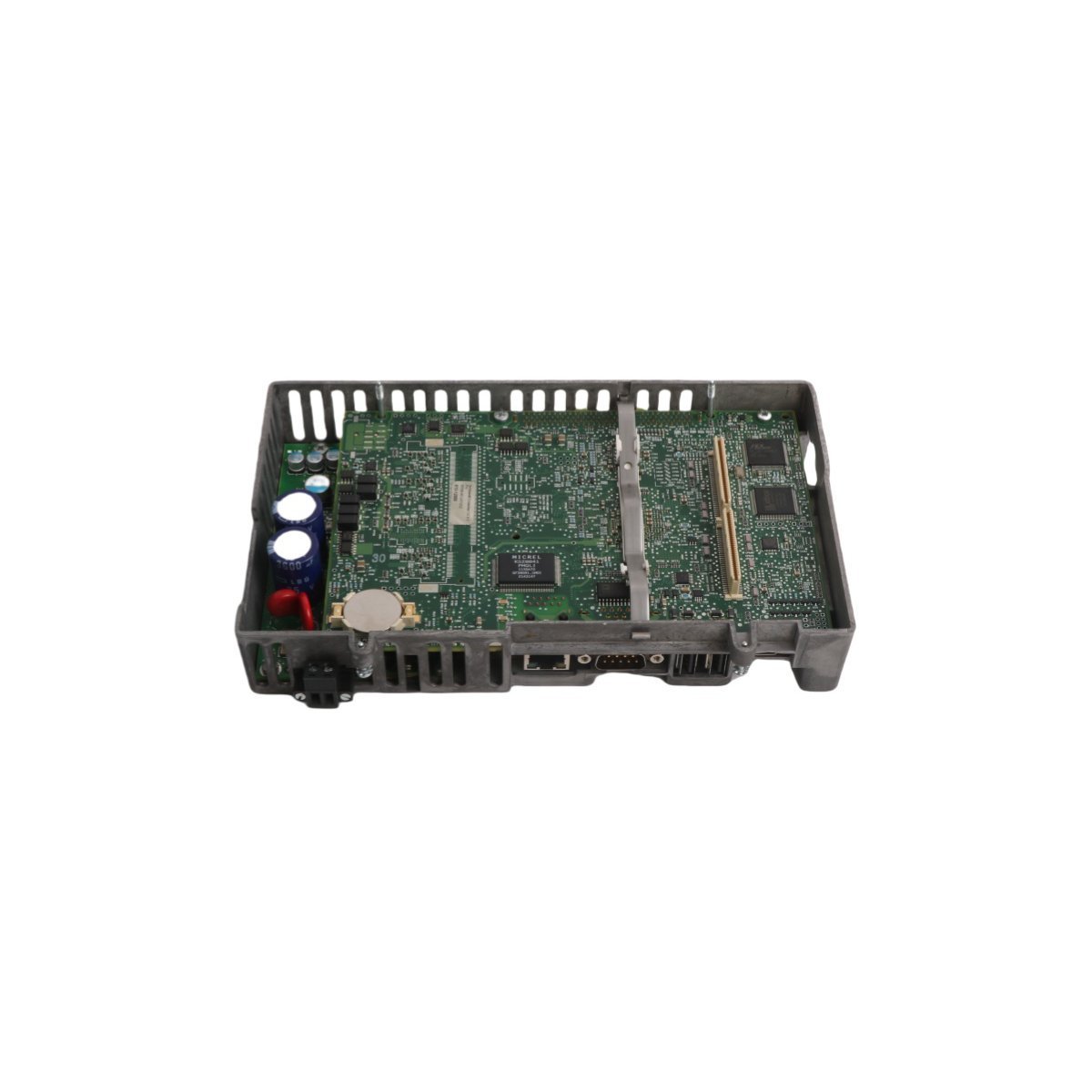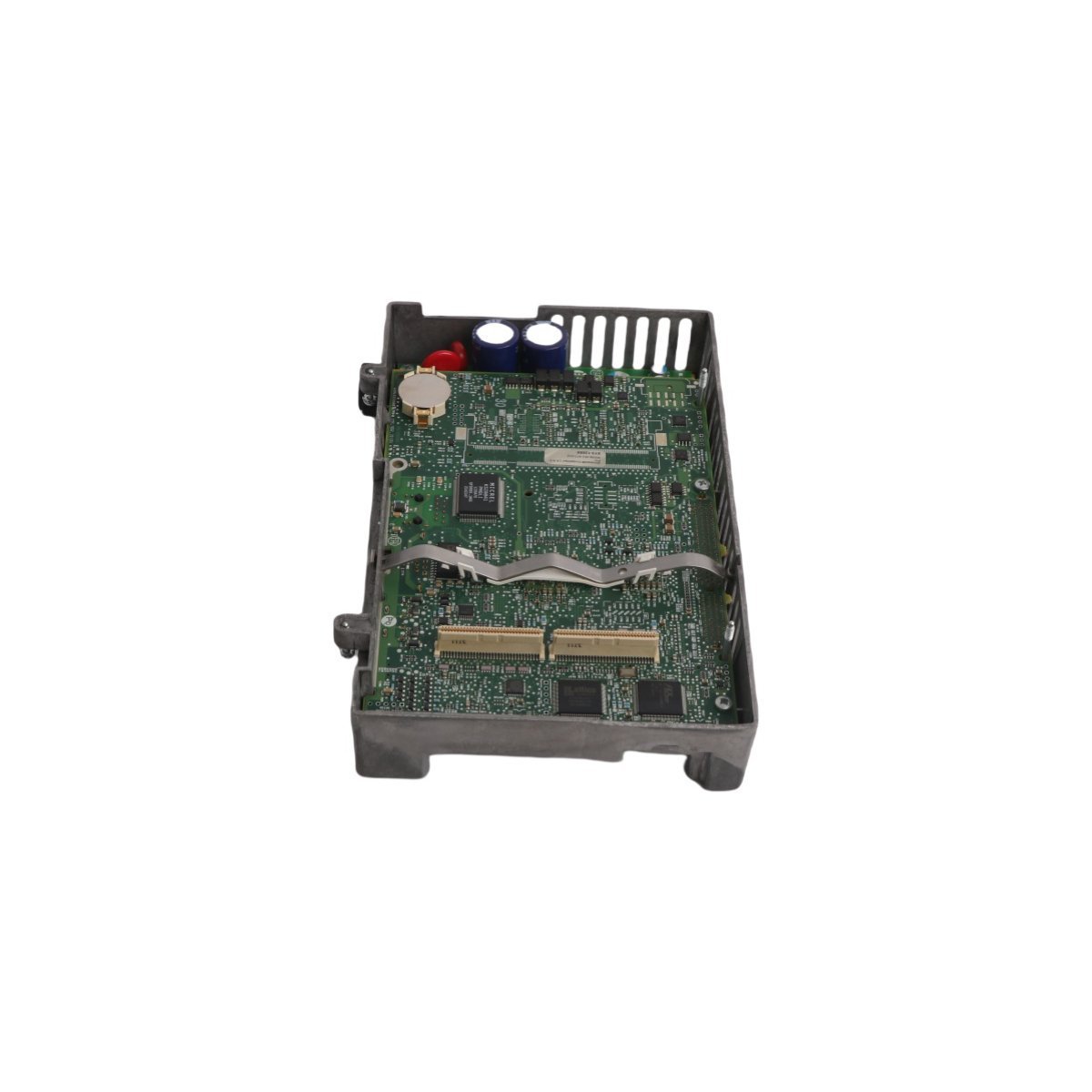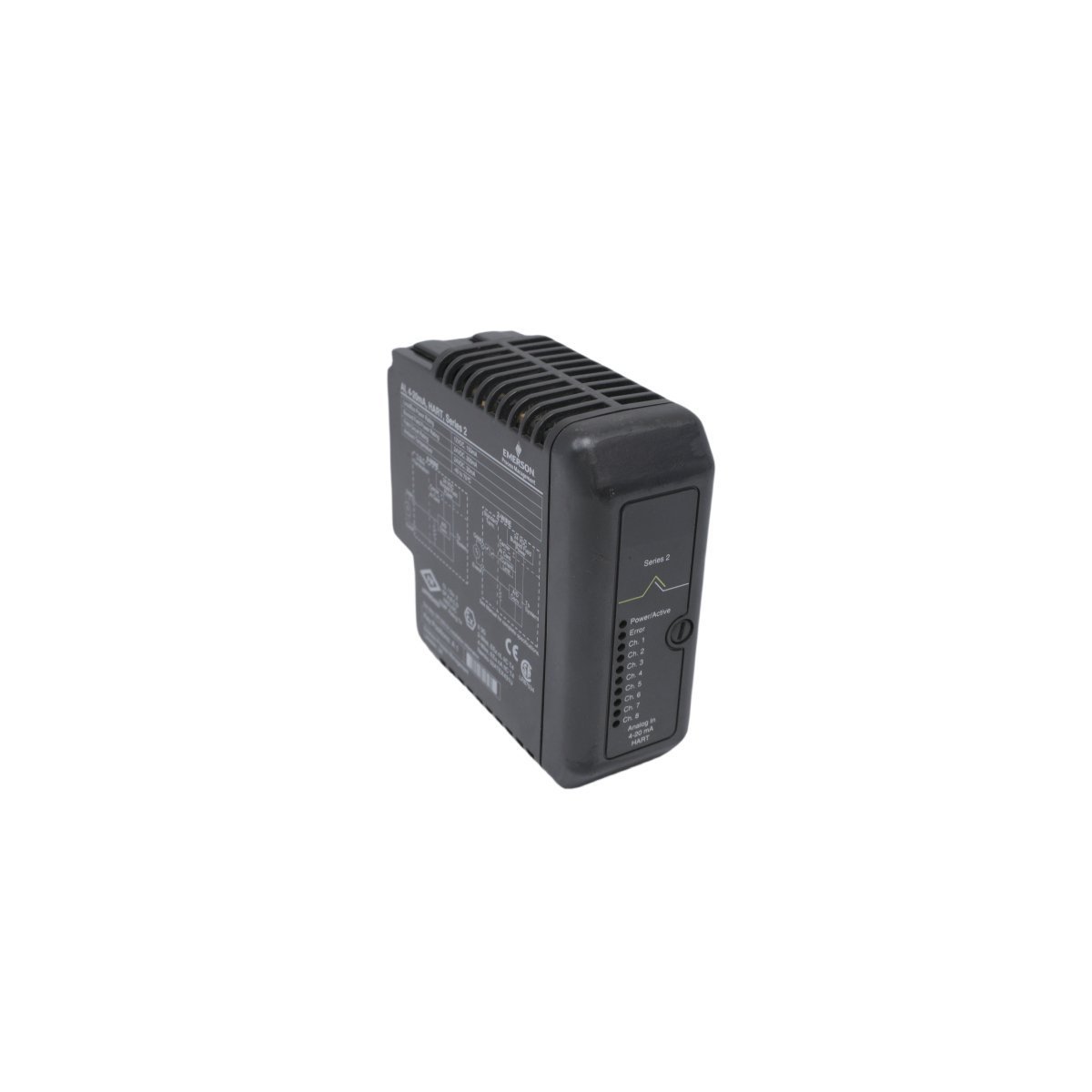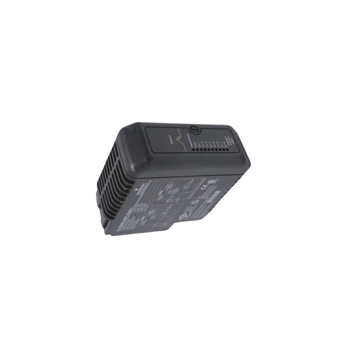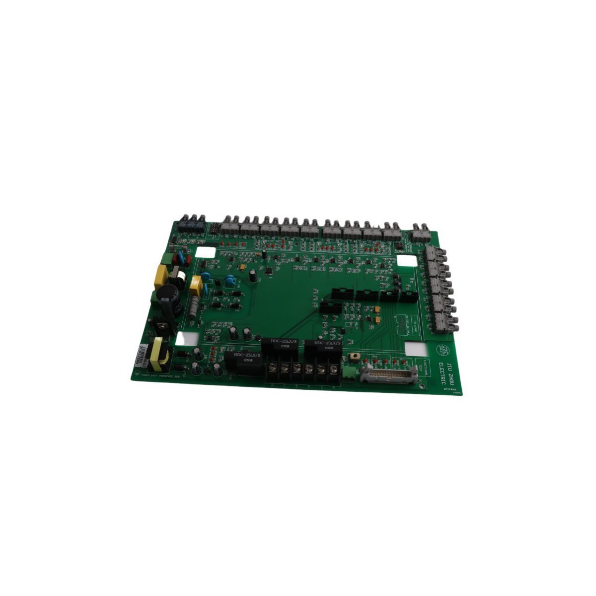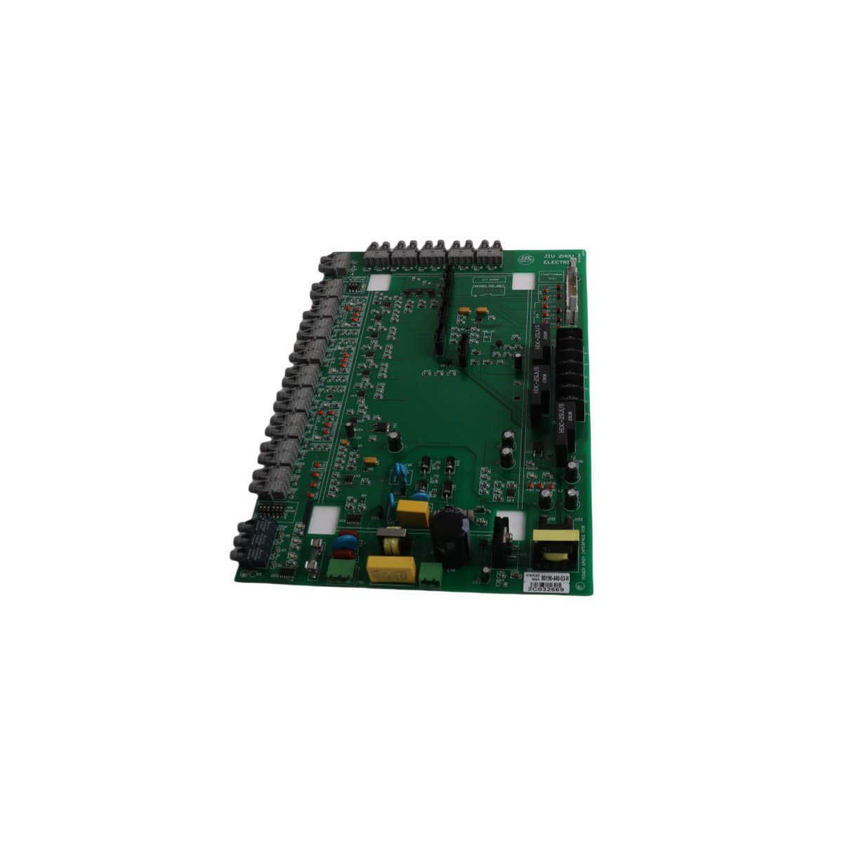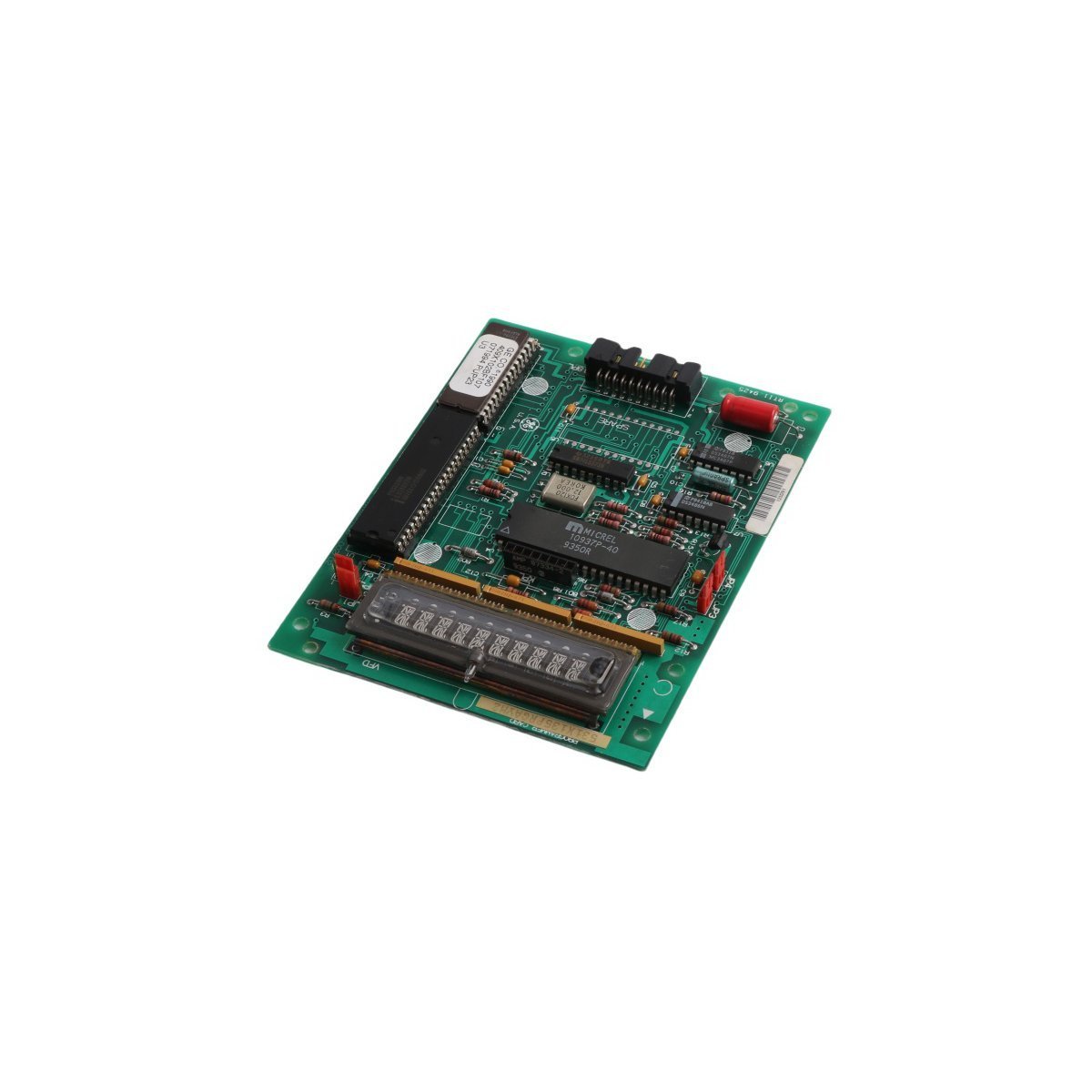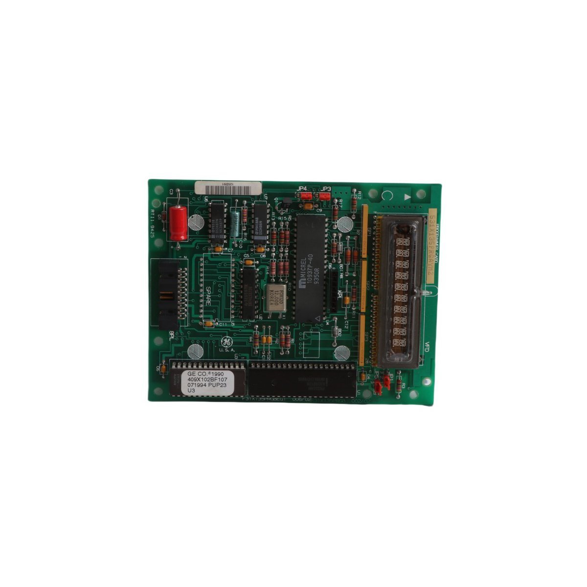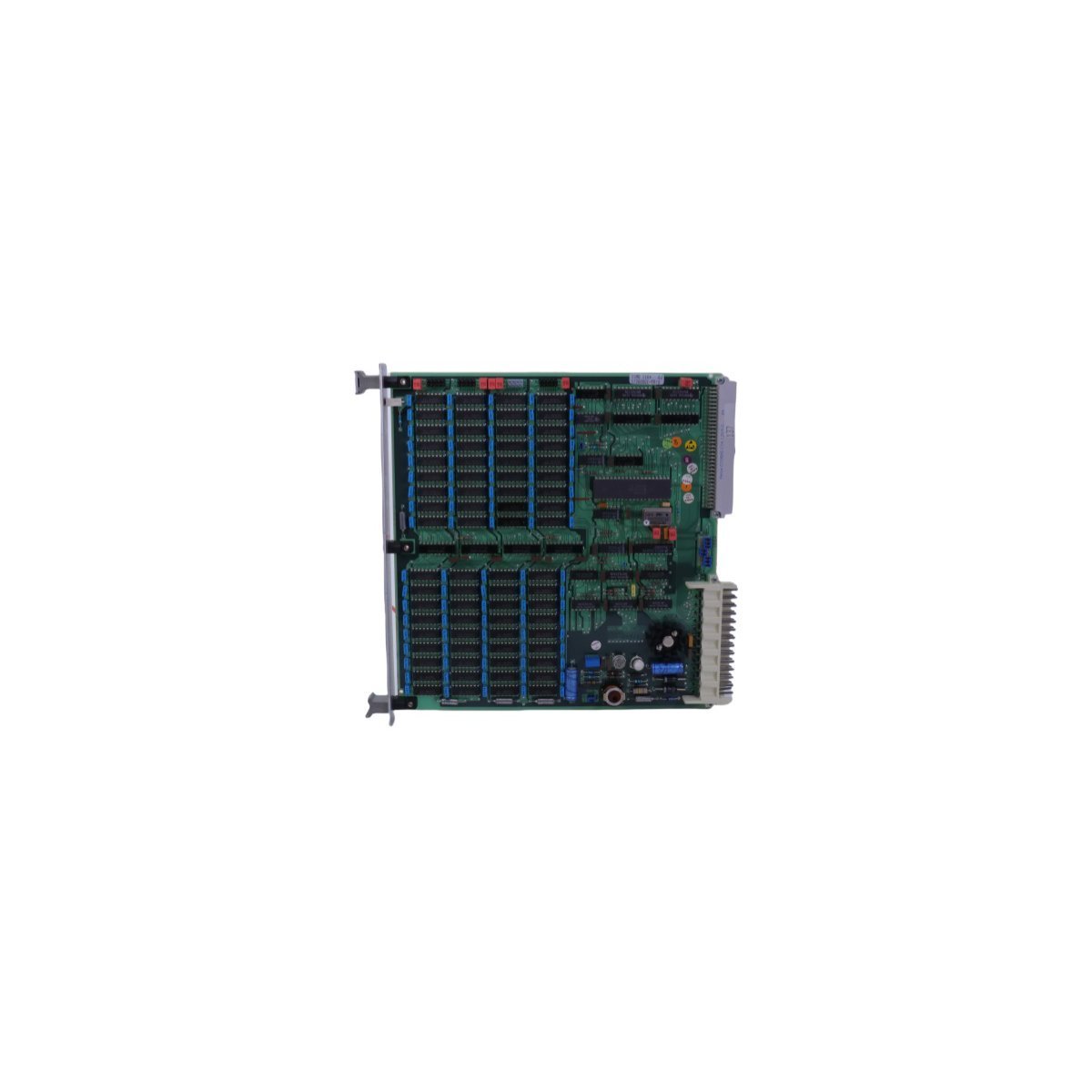
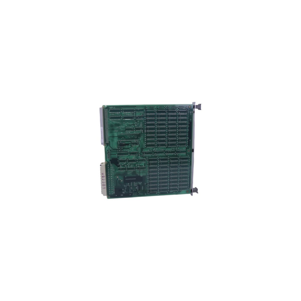
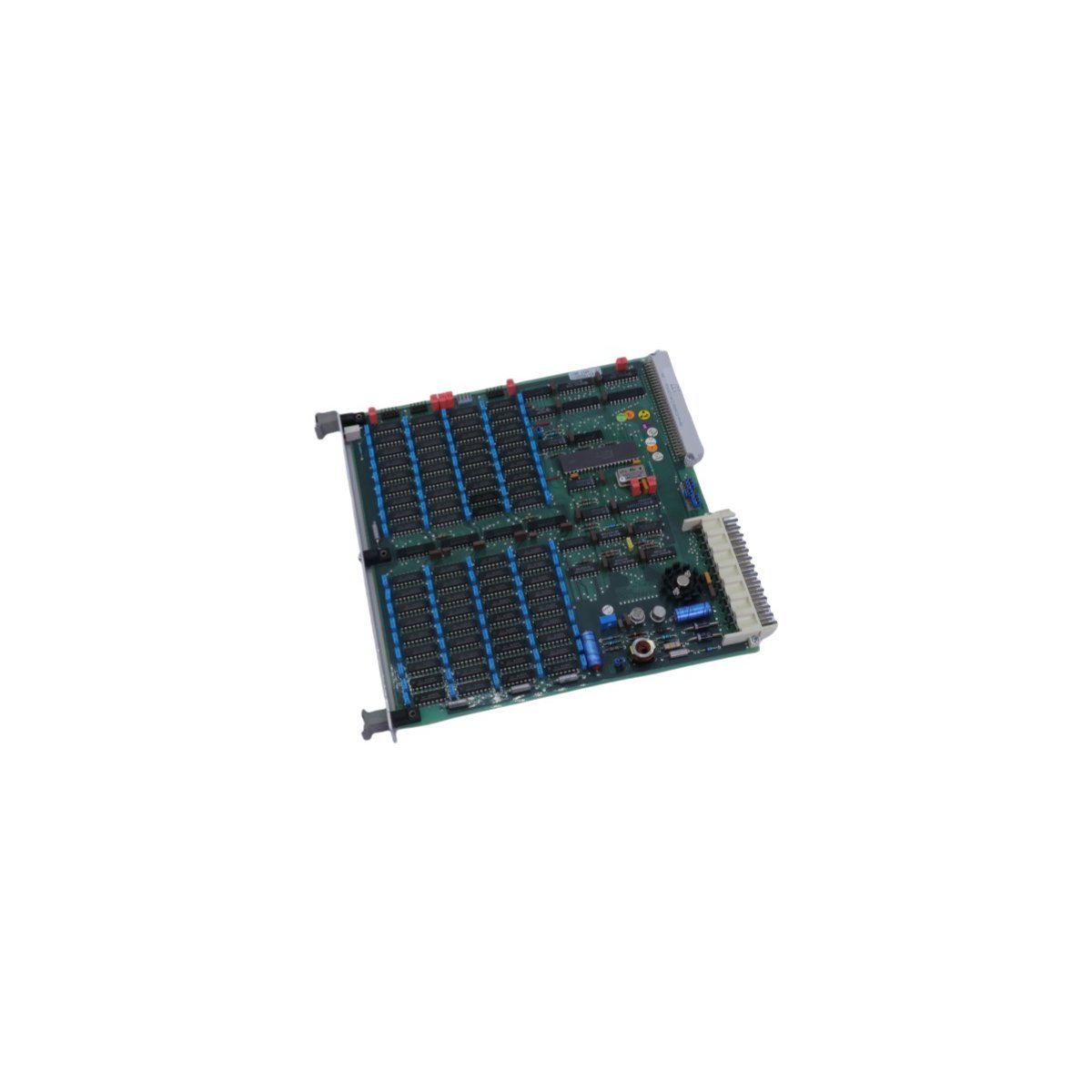
The ABB DSMB116 5736 0001-EB is a high-performance memory module designed for MasterPiece DCS units. This Swedish-made PC board features an integrated RS-232 interface and Ethernet routing capabilities, providing reliable data storage and communication for complex industrial automation environments.
The ABB DSMB116 (5736 0001-EB) serves as a specialized memory expansion component designed for the MasterPiece series within decentralized control systems (DCS). This module provides the critical data storage infrastructure required to execute complex automation logic and maintain system parameters. Because it utilizes high-grade semiconductor technology, the board ensures rapid data access while maintaining a low thermal footprint, which effectively extends the service life of surrounding electronic components.
Technical Specifications
Brand: ABB
Model: DSMB116
Part Number: 5736 0001-EB
Series: MasterPiece / Advant Controller
Product Type: Memory Board / PC Board
System Compatibility: DCS / Industrial Control Systems
Communication Interface: RS-232 Integrated Port
Weight: 0.46 kg
Dimensions: 20 x 249 x 244 mm
Origin: Sweden
Functional Role: Ethernet Routing and Data Buffering
Operational Characteristics
The DSMB116 module incorporates robust architecture to withstand the rigors of industrial environments. Furthermore, its mechanical design provides significant resistance to high-frequency vibrations and mechanical shocks, ensuring continuous uptime in heavy-duty applications. Since the module supports ABB’s proprietary communication protocols, it facilitates seamless synchronization between the central processing unit and peripheral control devices.
In addition to its storage capabilities, the board functions as an Ethernet router within the DCS network, thereby streamlining data traffic and reducing latency during high-load operations. Engineers can easily integrate this unit into existing MasterPiece configurations due to its plug-and-play compatibility, which significantly simplifies the maintenance and upgrade cycle. Consequently, this memory module represents a reliable solution for operators seeking to stabilize their industrial automation performance.
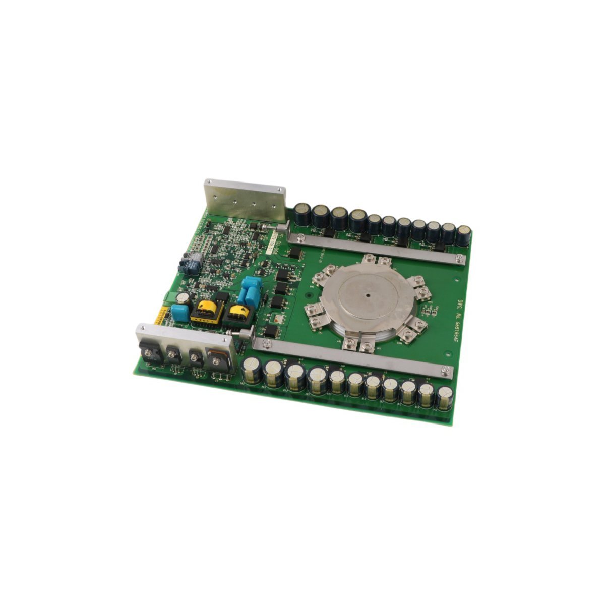
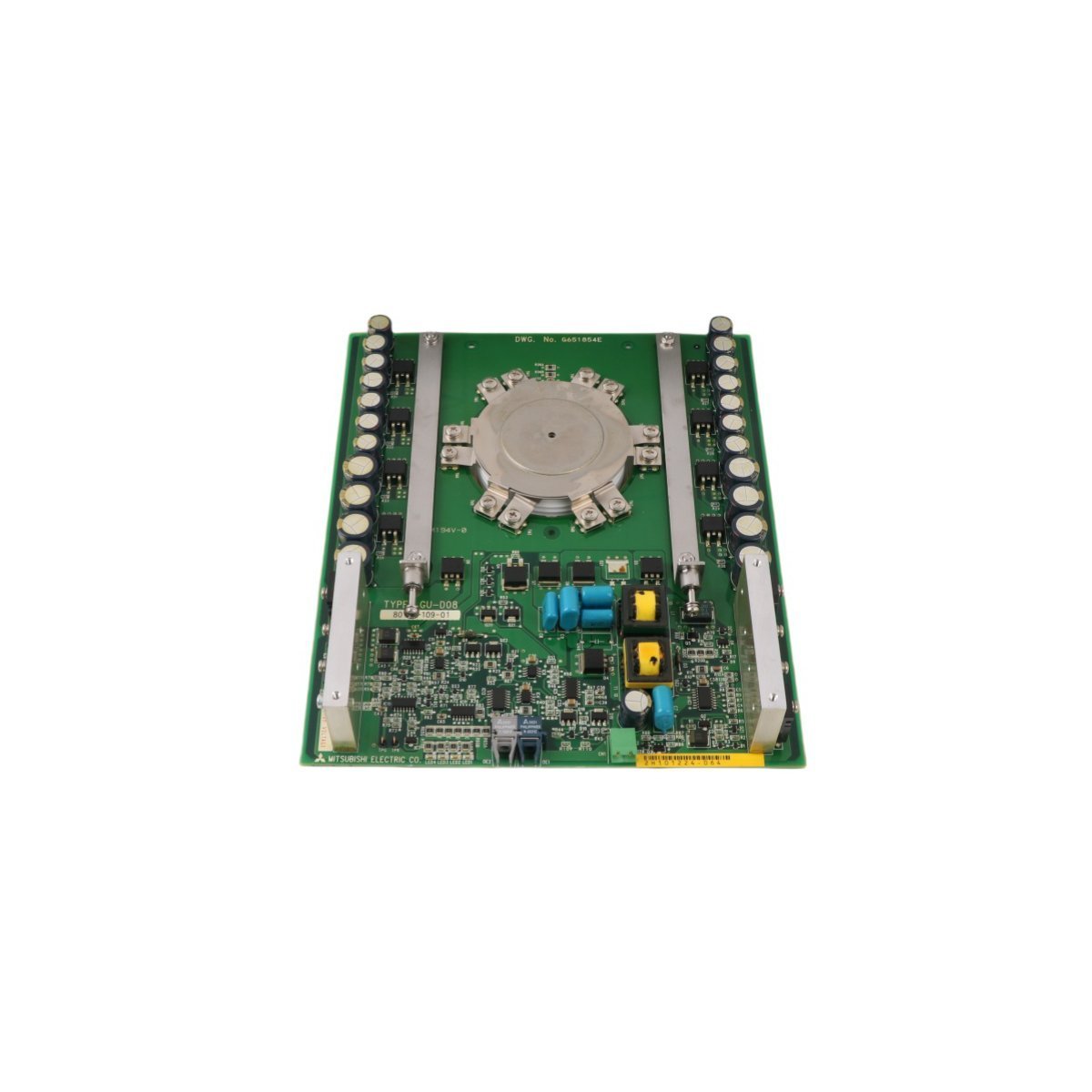
The Allen Bradley 81001-451-62-R, also cataloged as the 81001-451-62-R 1500 Amp SGCT Matched Set, operates as a dedicated hardware component for high-current semiconductor switching and power regulation within medium voltage industrial drive systems.
The module integrates directly into high-power inverter assemblies, utilizing backplane bus communication velocity and EtherNet/IP deterministic networks to maintain synchronized gate firing sequences. The factory-matched symmetrical gate commutated thyristor (SGCT) arrangement preserves uniform current distribution across parallel semiconductor junctions. Internal firmware flash compatibility ensures seamless coordination with main system power processors, optimizing gate pulse timing and preventing localized thermal hotspots during full load execution.
Frequently Asked Questions
Q: Why must SGCT components be replaced as a matched set?A: Matched sets are calibrated at the factory to exhibit identical forward voltage drop and turn-on/turn-off switching characteristics. Replacing individual devices instead of the full matched set causes uneven current distribution, leading to premature semiconductor breakdown.Q: What precautions should be taken regarding drive bus discharge before handling?A: High-voltage DC bus capacitors connected to the assembly must be fully discharged and verified with a calibrated multimeter before physical removal or installation to prevent severe electrical shock or component destruction.
Field Installation Guidelines
Verify that all main incoming three-phase AC power and auxiliary control power feeds are disconnected, locked out, and tagged prior to accessing the enclosure.
Handle the matched SGCT devices using proper ESD protection protocols, including a grounded wrist strap attached to the metal frame of the drive enclosure.
Inspect thermal contact surfaces for contaminants; apply a thin, uniform layer of specified thermal conductive grease before mounting to the heatsink.
Use a calibrated torque wrench to tighten mounting hardware according to specified mechanical tolerances to ensure proper electrical contact and thermal dissipation.
Route gate driver signal cables away from high-current busbars to mitigate electromagnetic interference and false firing signals.
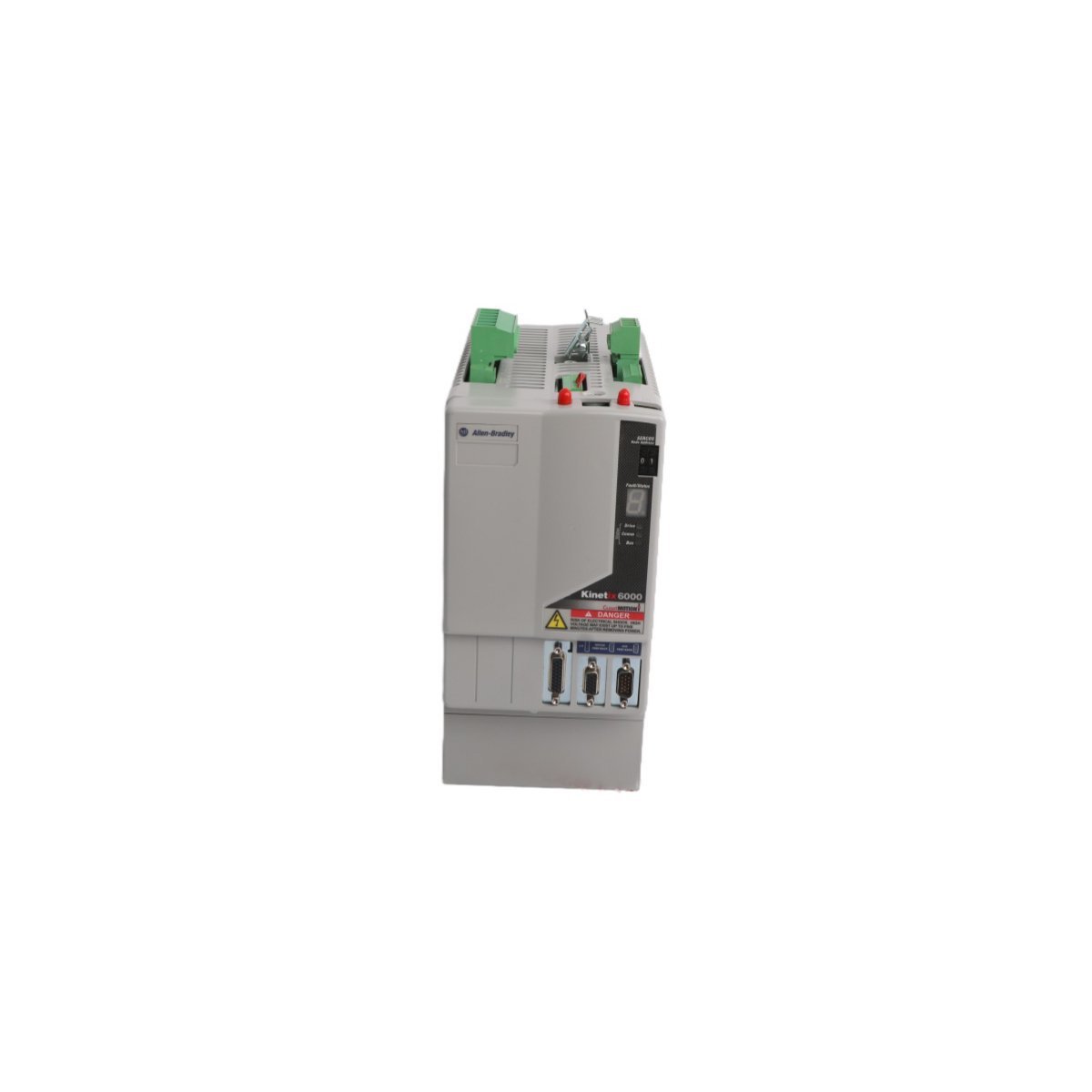
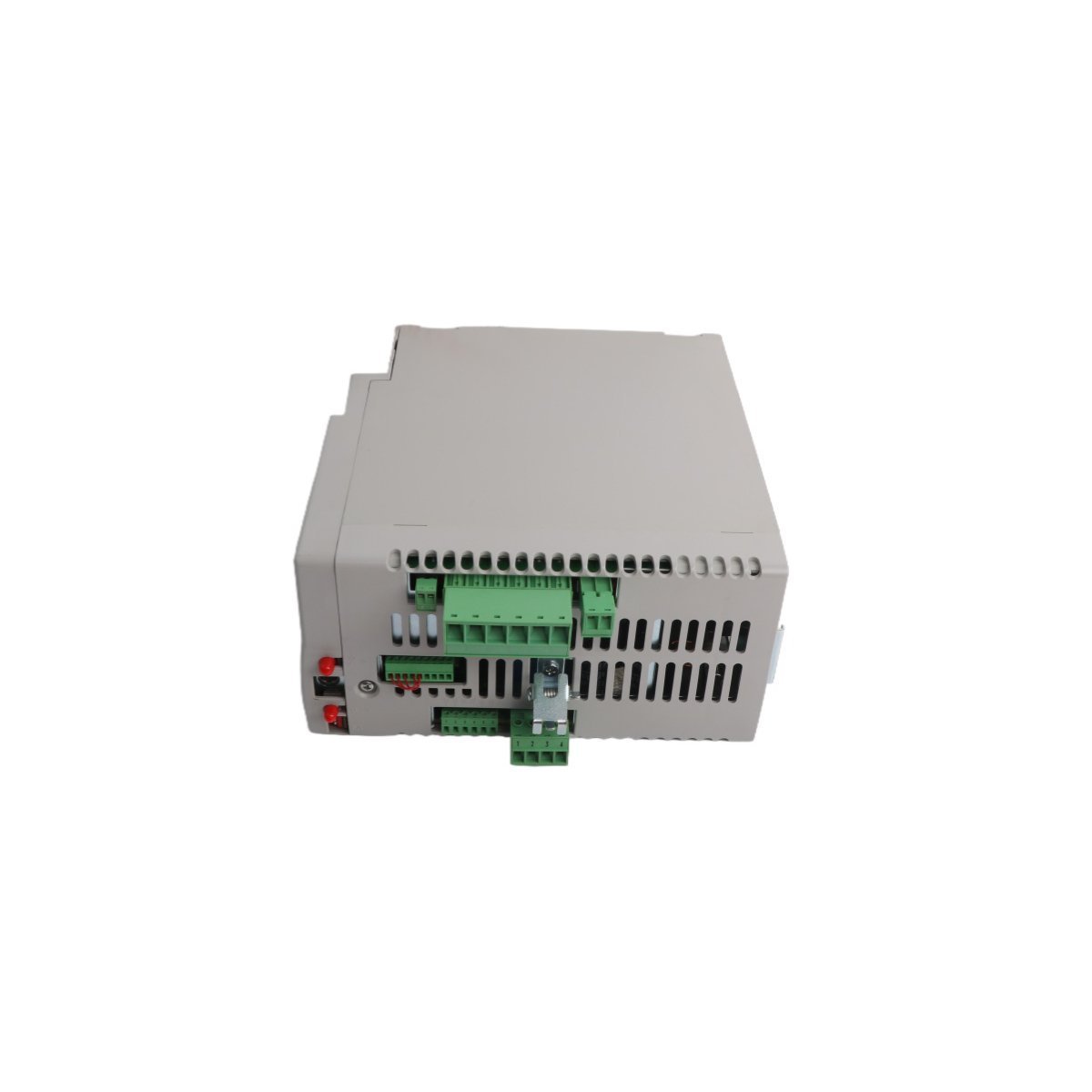
The Allen-Bradley 2094-BC02-M02-M, also cataloged as the 2094-BC02 Integrated Axis Module, operates as a dedicated hardware component for AC line power rectification and axis motion execution within Kinetix 6000 multi-axis servo systems. It converts three-phase AC input voltage into a regulated DC bus supply while simultaneously controlling a single servo axis inverter output. The module features embedded hardware-based Safe Torque-Off (STO) logic, solid-state motor short-circuit monitoring, and direct interface links for multi-axis power sharing across external drive rails.
Hardware Specifications
Parameter
Specification
Model
2094-BC02-M02-M
Brand
Allen-Bradley
Origin
USA
Module Type
Integrated Axis Module (IAM)
System Architecture
PLC / Kinetix 6000 Multi-Axis Servo
Input Voltage Range
360-480 VAC, 3-Phase
Converter Power Rating
15 kW / 23 A
Inverter Power Rating
6.6 kW / 14.6 A
Heat Dissipation
44 W (Converter), 72 W (Inverter)
Short Circuit Rating
200000 A (Fused), 65000 A (Circuit Breaker)
Integrated Safety
Safe Torque-Off (STO)
Control Input Fuse Recommendation
Bussmann FNQ-R-10 (10 A)
DC Bus Power Fuse Recommendation
Bussmann FWJ-40A
HS Code
8537101190
Dimensions
12.7 cm x 29.2 cm x 25.4 cm
Weight
5.6 kg
Operating Temp
0 to 50 deg C
EtherNet/IP and SERCOS Deterministic Network Integration
The module coordinates real-time synchronization using EtherNet/IP and SERCOS communication interfaces. High-speed position and velocity loop data flow deterministically between the central Logix controller and the drive inverter stages over cyclic network slots. Internal timing hardware synchronizes multi-axis motion cycles to reduce axis skew. Integrated diagnostic registers transmit voltage levels, thermal status, phase loss detections, and motor fault flags back to the controller without dedicated external sensor wiring.
Frequently Asked Questions
Q: What branch circuit protection fuses are mandated for input power isolation?A: Control input power loops require Bussmann FNQ-R-10 (10 A) fuses, while the DC bus power link requires Bussmann FWJ-40A fuses to achieve a 200000 A short-circuit current rating (SCCR).Q: How does the integrated Safe Torque-Off (STO) function operate electronically?A: The STO circuit directly disables the gate drive signals to the output power transistors (IGBTs), preventing the inverter from generating motor torque without removing main line input power from the power supply stage.Q: What are the thermal dissipation metrics during partial load operations?A: Under standard partial load conditions, the internal converter section dissipates 44 W of heat, and the internal inverter section dissipates 72 W of heat into the cabinet enclosure.
Field Installation Guidelines
Enclosure Clearance and Thermal Mounting: Mount the module vertically on a flat, grounded surface inside an IP54 or NEMA 12 industrial enclosure. Maintain a minimum vertical clearance of 50 mm above and below the chassis to allow unimpeded convection airflow through the heat sink assembly.
Grounding and Shielding Protocols: Connect the module ground lug directly to the central enclosure ground bus using a low-impedance stranded copper conductor. Motor power cables must utilize 360-degree continuous metallic braid shielding clamped directly to the chassis ground plate to suppress high-frequency electromagnetic interference (EMI).
Power and DC Bus Terminal Wiring: Ensure three-phase 360-480 VAC line power is disconnected before accessing input terminal blocks. Verify correct terminal polarity on shared DC bus link bars when interconnecting additional follower axis modules on the power rail. Torque all power terminal screw connections to the vendor-specified mechanical limits.
The Allen Bradley 2711P-RP1X, also cataloged as the 2711P-RP1 Logic Module, operates as a dedicated hardware component for graphical execution and display processing within PanelView Plus terminal architectures.
The module executes real-time protocol processing for deterministic EtherNet/IP communications across backplane architectures. Dedicated onboard memory registers handle high-density I/O polling and tag synchronization directly from ControlLogix processors without CPU cycle starvation. High-speed bus arbitration ensures minimal latency during real-time data frame transfers between external PLC controllers and internal application runtime instances.
Frequently Asked Questions
Q: Can the 2711P-RP1X logic module be attached to any PanelView Plus display module size?A: The module mechanically attaches to PanelView Plus display modules ranging from 700 to 1500 series configurations using standard retention screws.Q: How is thermal dissipation handled during continuous panel enclosure mounting?A: Heat dissipation occurs passively via the rear enclosure heat sink ribs; maintaining 50 mm clearance around all ventilation slots prevents internal thermal throttling.
Field Installation Guidelines
Disconnect all primary DC power inputs from the terminal base prior to mating or unseating the logic module from the display housing.
Torque all rear structural locking screws to 1.1 Nm (10 in-lb) to maintain uniform contact force across internal board-to-board connectors.
Route network communication cables through dedicated wire raceways separated from 120/230 VAC power feeds by at least 200 mm.
Verify proper panel ground bond resistance of less than 1 ohm between the module chassis ground terminal and the main enclosure earth bus.
The Allen Bradley 81001-450-52-R Power Block Drive, also cataloged as the 81001-450-52-R Power Block Drive, operates as a dedicated hardware component for power distribution and conversion within PLC platform networks.
Hardware Specifications
Parameter
Specification
Model
81001-450-52-R
Brand
Allen Bradley
Origin
USA
Weight
1.14 kg
Dimensions
25 x 20.7 x 5.5 cm
Operating Temp
Standard Industrial Range
Power Consumption
System Dependent
Module Type
Power Block Drive
PLC Deterministic Network Integration
The Allen Bradley 81001-450-52-R utilizes backplane bus communication protocols designed for integration with PLC control architectures. The module supports deterministic network timing, ensuring low-latency power state feedback and synchronization within complex I/O density configurations. Compatibility with field-programmable firmware allows for flash updates to align with evolving backplane bus communication velocity requirements, maintaining bus traffic integrity and reducing collision potential in high-speed control loops.
Frequently Asked Questions
Q: What are the restrictions regarding the installation of the 81001-450-52-R in a redundant power rack?A: Ensure that the backplane bus address is correctly configured to prevent signal collisions. Redundant power configurations must be verified for voltage matching before closing the primary disconnect.Q: Is this module capable of firmware field-upgrades?A: Yes, the unit supports firmware flash compatibility via the primary control bus. Consult the PLC backplane interface documentation for current revision requirements.
Field Installation Guidelines
Mount the module onto a standard metal DIN-rail. Ensure the rail is bonded to the cabinet chassis ground to minimize EMI.
Maintain a minimum clearance of 50 mm above and below the unit to allow for passive thermal heat dissipation.
All power input cabling must utilize shielded twisted-pair conductors to prevent common-mode noise injection into the PLC backplane.
Verify that the 24 VDC output load does not exceed the continuous current rating specified for the associated PLC power bus segment.
Ensure the connector interface is fully seated until a tactile lock is achieved to prevent intermittent contact resistance.
The Allen Bradley 80190-378-51, also cataloged as the 80190-378-51 PC Board, operates as a dedicated hardware component for signal processing and logic execution within PLC-5 platform networks.
Hardware Specifications
Parameter
Specification
Model
80190-378-51
Brand
Allen Bradley
Origin
USA
Weight
0.46 kg
Dimensions
27.8 x 21.4 x 2.8 cm
Operating Temp
Standard Industrial Range
Power Consumption
System Dependent
Module Type
PC Board
PLC Deterministic Network Integration
The Allen Bradley 80190-378-51 utilizes backplane bus communication protocols designed for integration with PLC-5 control architectures. The module supports deterministic network timing, ensuring low-latency state feedback and synchronization within complex I/O density configurations. Compatibility with field-programmable firmware allows for flash updates to align with evolving backplane bus communication velocity requirements, maintaining bus traffic integrity and reducing collision potential in high-speed control loops.
Frequently Asked Questions
Q: What are the restrictions regarding the installation of the 80190-378-51 in an active PLC-5 backplane?A: Ensure that the backplane power is cycled off before insertion or removal to prevent electrical arcing on the connector pins. The module must be correctly seated in the chassis slot to maintain signal integrity across the backplane bus.Q: Is this module capable of firmware field-upgrades?A: Yes, the unit supports firmware flash compatibility via the primary control bus interface. Verify the current revision against the specific PLC-5 processor requirements before initiating any update sequence.
Field Installation Guidelines
Mount the PC Board into a standard PLC-5 chassis. Ensure the mounting screws are tightened to the specified torque to guarantee a secure electrical chassis ground connection.
Avoid exposing the component to electrostatic discharge (ESD). Utilize a grounded wrist strap when handling the board.
Ensure all backplane pins are free of debris or oxidation before installation.
Maintain ambient operating temperature within the specified industrial limits to prevent thermal degradation of on-board components.
Verify that the backplane power supply capacity is sufficient for the total I/O density load when the module is initialized.
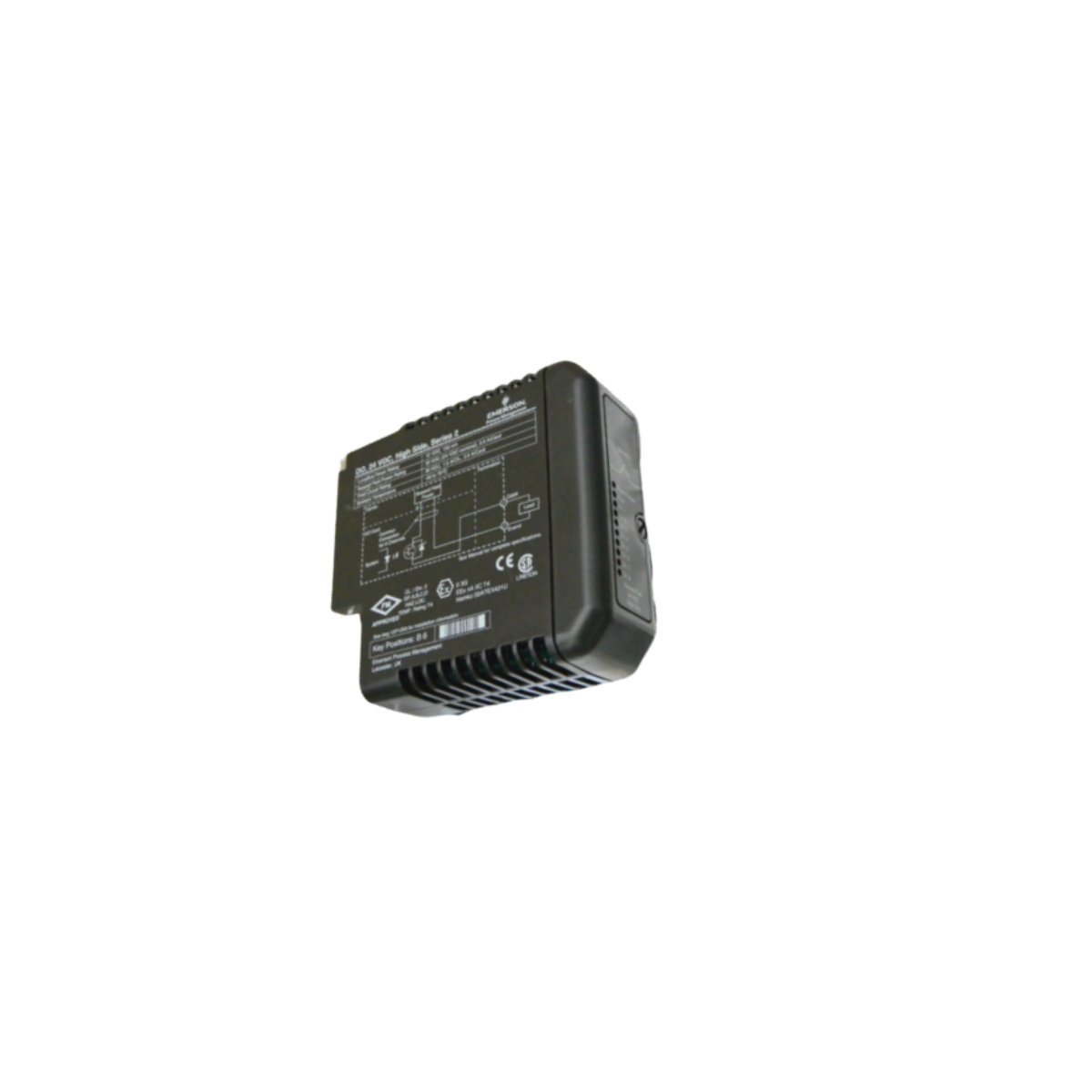
Configured for signal distribution in DeltaV M-series I/O subsystems, the Emerson KJ3222X1-BA1 (KJ3222X1-BA1 Redundant Terminal Block) provides direct physical and electrical execution of field wiring termination for redundant I/O configurations.
Hardware Specifications
Parameter
Specification
Model
KJ3222X1-BA1
Brand
Emerson
Origin
USA
Weight
0.2 kg
Dimensions
4.1 x 12.5 x 10.5 cm
Operating Temp
Standard Industrial Range
Power Consumption
Passive Component
Compatibility
DeltaV M-series I/O
DeltaV DCS Process Control Characteristics
The terminal block facilitates the implementation of 4-20 mA HART loop protocol architectures by providing physical connection points for redundant I/O card pairs. It maintains channel-to-channel isolation through optimized PCB routing, preventing cross-talk between high-density loops. The mechanical design ensures cold junction compensation (CJC) stability when integrated with thermocouple input channels. By utilizing the redundant terminal architecture, the system maintains continuous signal integrity for critical control loops, allowing for maintenance operations on one I/O module without disrupting the current loop of the secondary redundant partner.
Frequently Asked Questions
Q: Does the KJ3222X1-BA1 support active electronic components?A: No, this is a passive terminal block. It serves as an interface between field wiring and the DeltaV I/O carrier, routing signals to the redundant I/O module pair.Q: Can this terminal block be used for non-redundant I/O configurations?A: While designed for redundancy, the terminal block provides the physical interface required for specific DeltaV M-series modules. Compatibility must be verified against the specific I/O module part number (VE4033S2B1) to ensure pin mapping alignment.
Field Installation Guidelines
Prior to wiring, verify that the I/O carrier power is disconnected to prevent accidental contact with energized field circuits.
During installation, align the terminal block with the mating connectors on the DeltaV I/O carrier, ensuring the guide pins are fully seated before tightening the retention screws.
When connecting field devices, ensure that shielded, twisted-pair cabling is utilized for all 4-20 mA loops to mitigate electromagnetic interference.
Upon securing the wiring, verify the continuity of the redundant paths using a digital multimeter at the terminal points before initiating loop commissioning.
Maintain appropriate physical separation between the terminal block wiring and any high-voltage AC lines to prevent induced noise on the analog signal loops.
The GE DS200TCEAG1BTF is a dedicated Emergency Overspeed Board for the Mark V turbine control system. It features an integrated microprocessor and hardware-based protection to monitor turbine velocity and execute critical safety trip functions reliably.
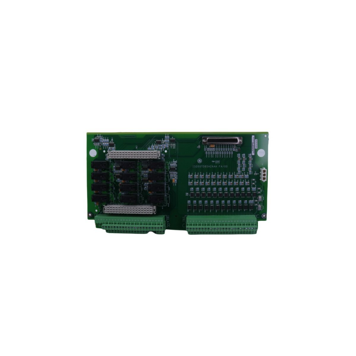
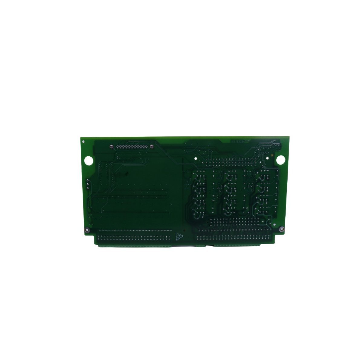
The GE IS200TDBSH2A is a Mark VI discrete simplex terminal board designed for turbine control systems. It provides 96 robust connection points for efficient signal management.
Allen-Bradley 2094-BM02-M single-axis Kinetix inverter module. Brand new original stock, multi-axis system configuration support, and global logistics options.
The Allen-Bradley SST-PFB-CLX is a ControlLogix PROFIBUS DP Master Scanner module that provides seamless integration between Rockwell controllers and PROFIBUS networks. It supports up to 12 Mbps data rates and features a dedicated configuration port for easy system setup.
The General Electric A06B-6290-H106 is a FANUC αi series servo amplifier module designed for precision CNC motion control. It features micron-level accuracy, regenerative power management, and advanced diagnostics for high-speed machining and automation.
The GE 531X307LTBAKG1 is a Multilin series I/O Terminal Board designed for high-precision signal processing in GE drive systems. It supports RS-422 communication, encoder feedback, and features configurable hardware settings for specialized industrial automation tasks.
We are committed to protecting your privacy. The information collected here is strictly used to provide the requested quotes, technical support, and relevant industrial automation solutions.