
Sale!
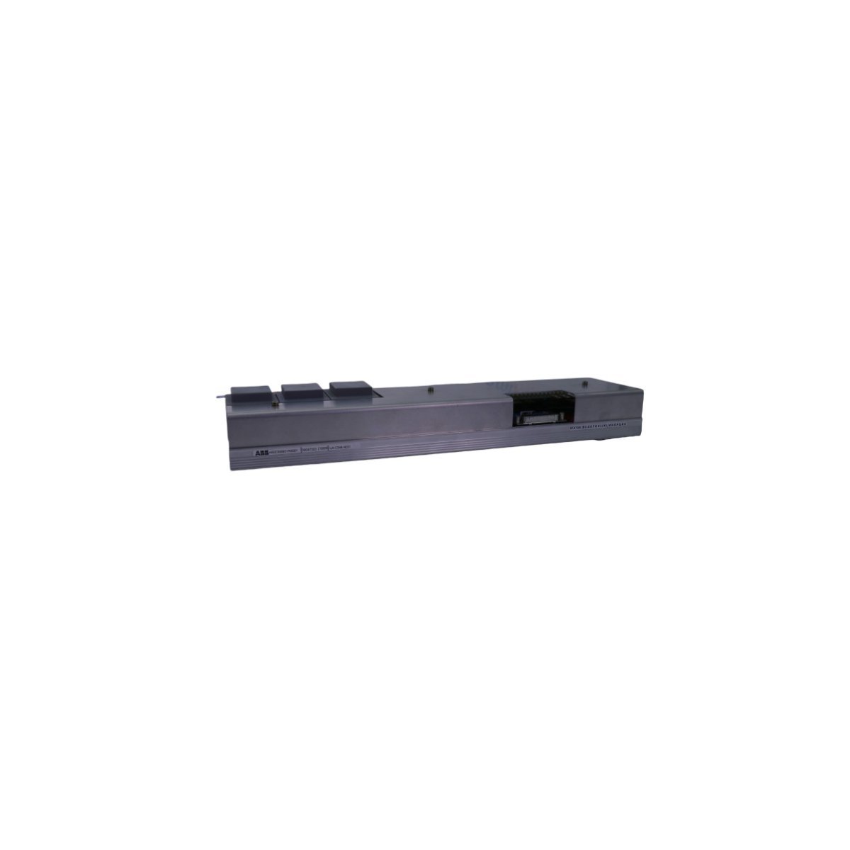
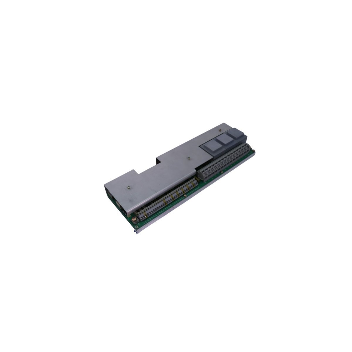
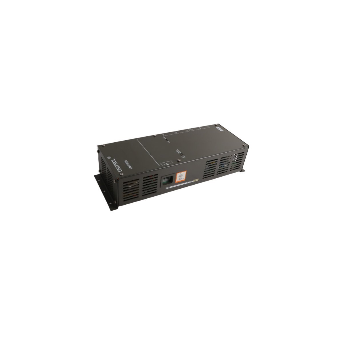
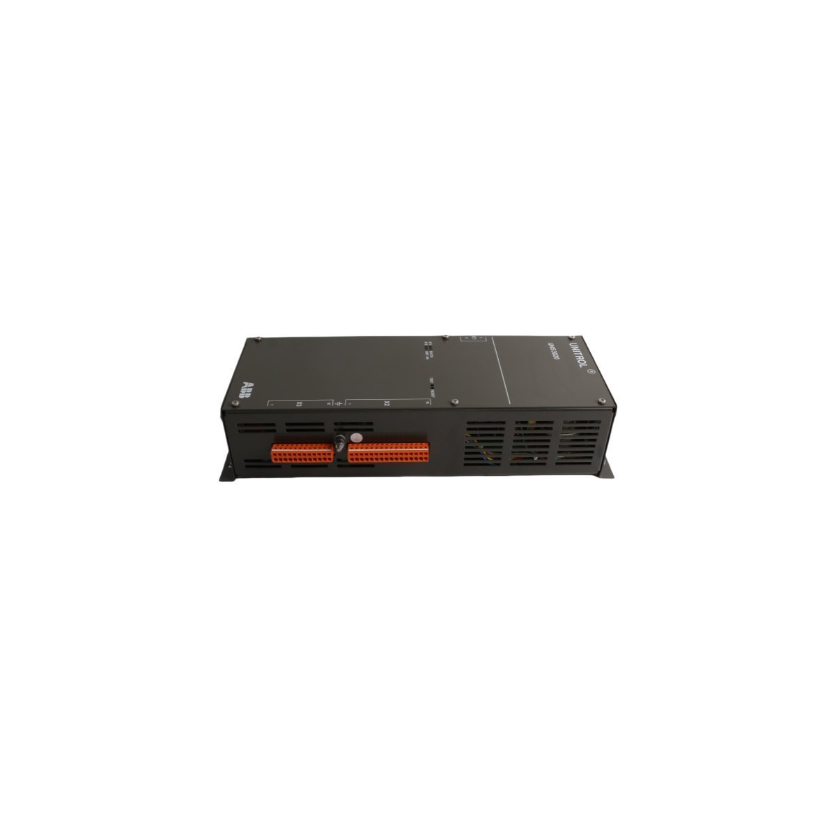
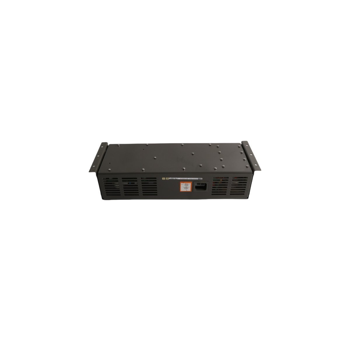
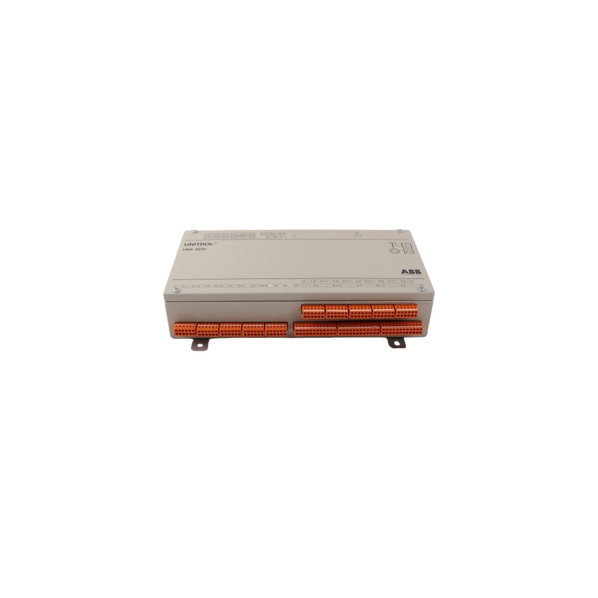
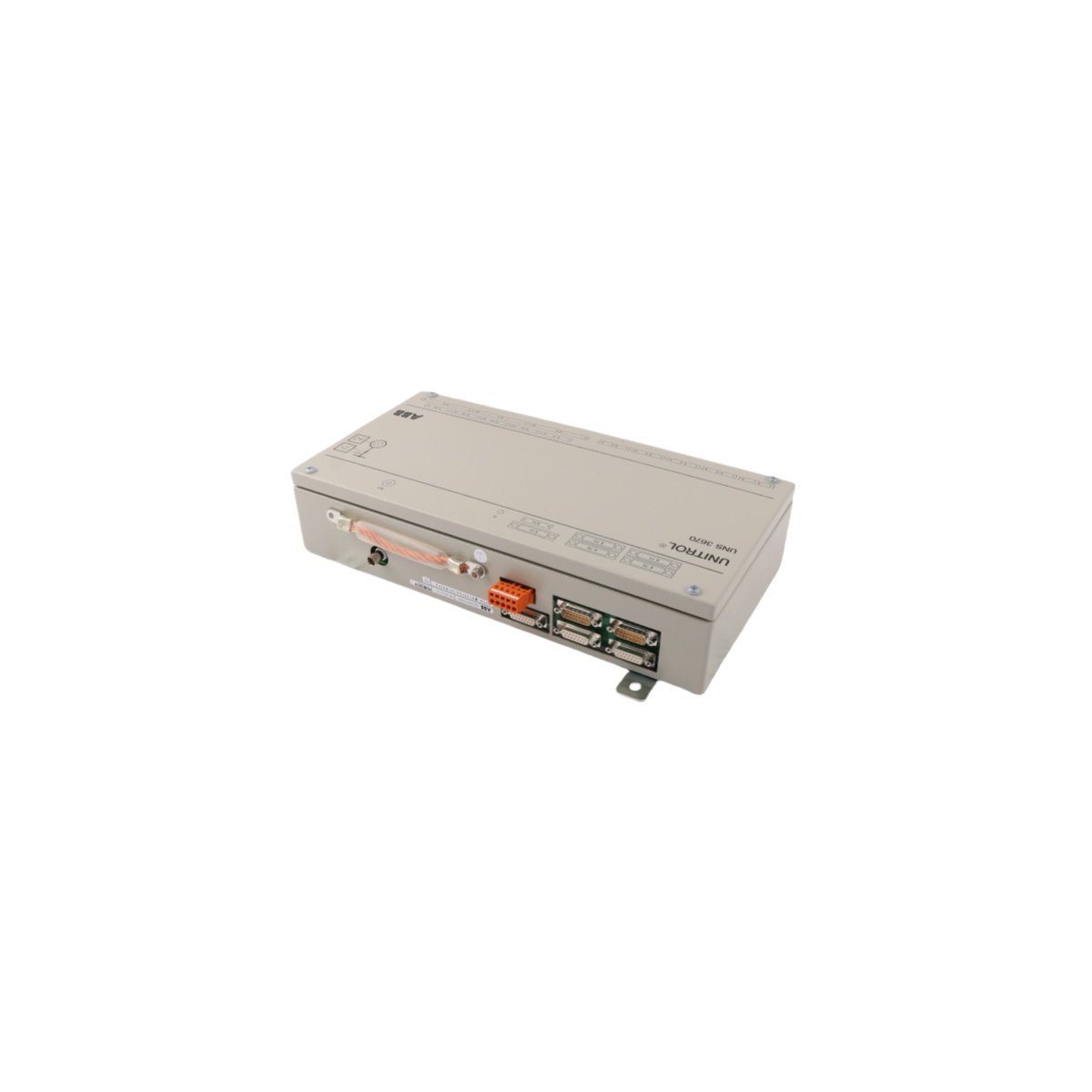
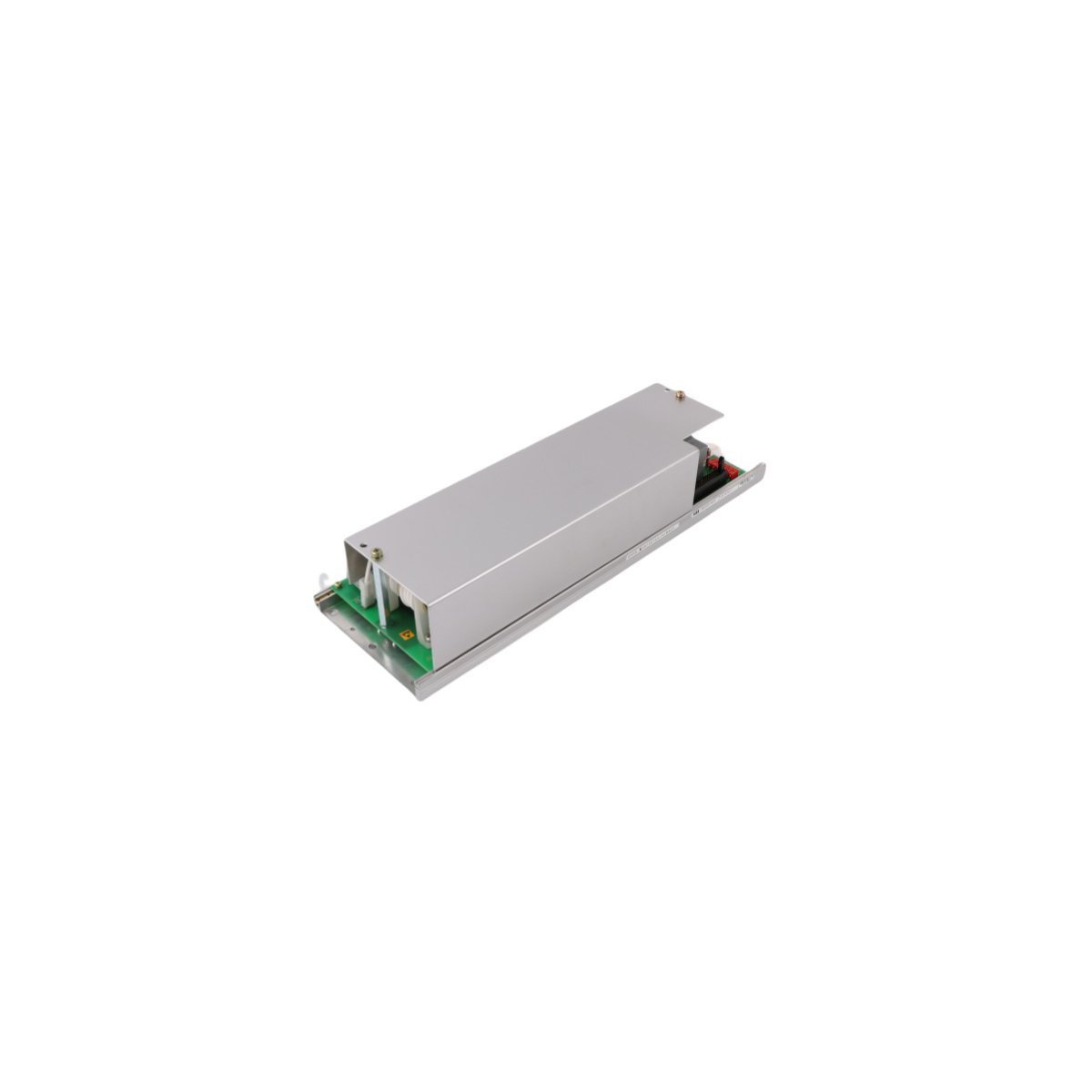
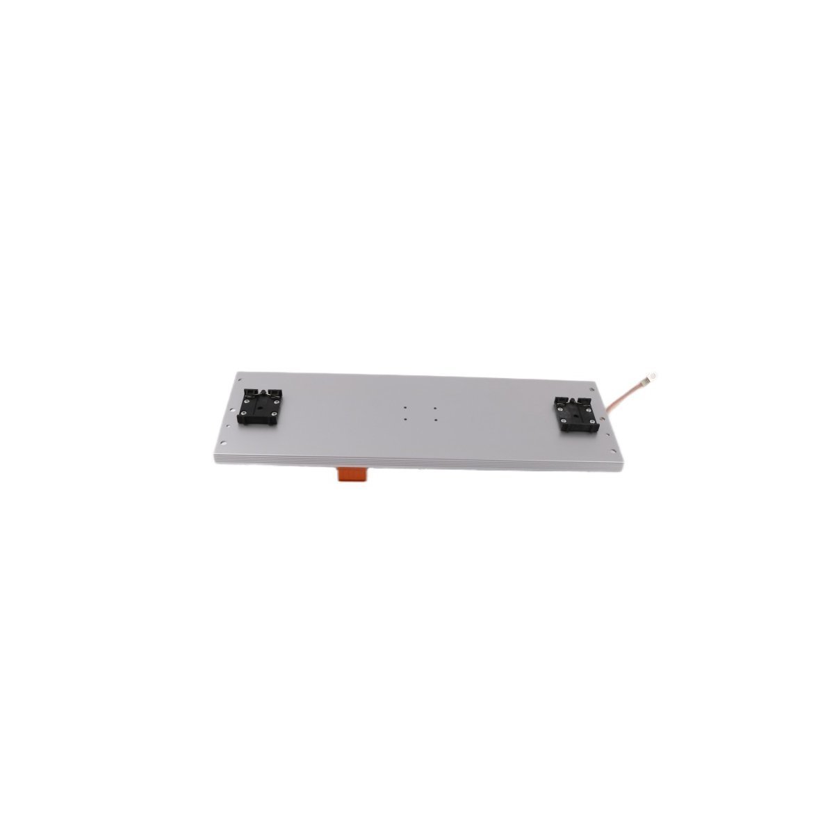
ABB UAC346AE01 (HIEE300831R0001) Binary Input Module
The ABB UAC346AE01 (HIEE300831R0001) is a specialized binary input module for UNITROL 5000 excitation systems. It ensures secure and reliable signal monitoring in power plants.
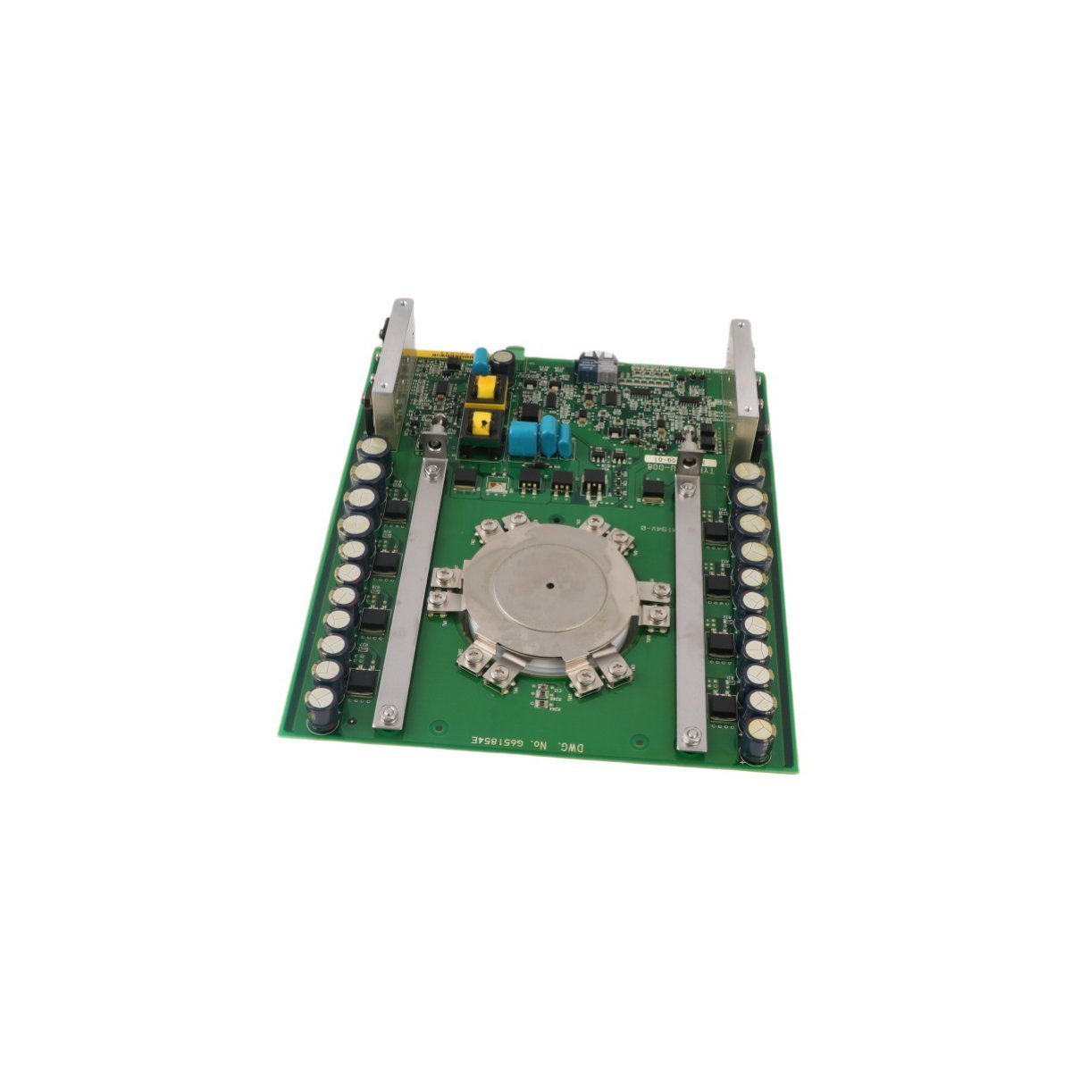
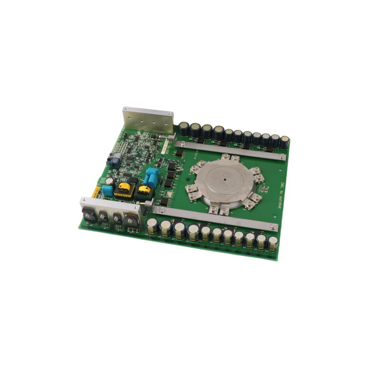
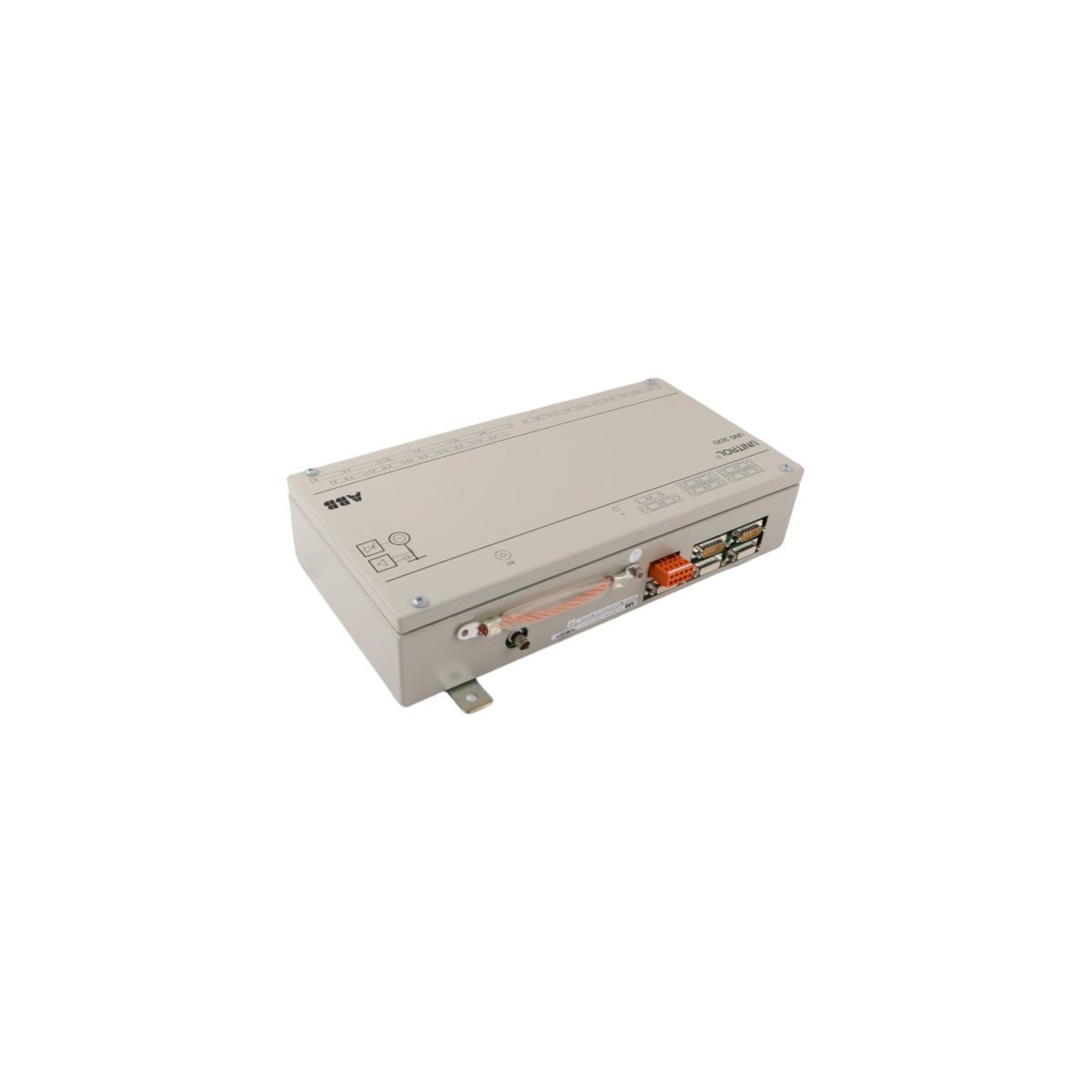
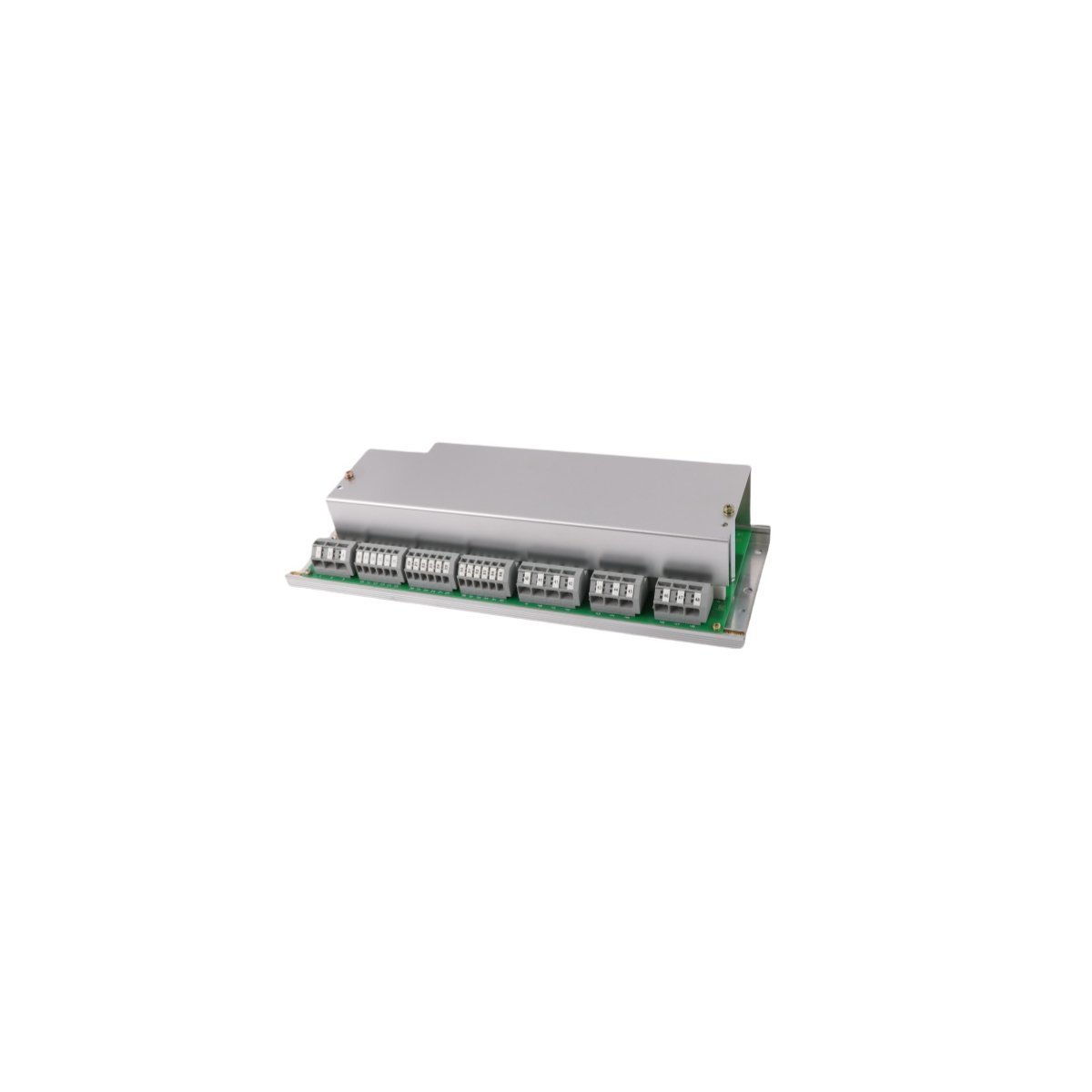
Configured for high-speed ground fault detection in UNITROL 5000 excitation systems, the ABB HIEE205010R0003 UNS3020A-Z,V3 (UNS3020A-Z,V3 Ground Fault Relay) provides direct physical/electrical execution. It evaluates leakage current, drives auxiliary trip circuits, and provides real-time fault signal isolation across DCS backplanes.
| Parameter | Specification |
|---|---|
| Model | HIEE205010R0003 UNS3020A-Z,V3 |
| Brand | ABB |
| Origin | SWEDEN |
| Weight | 4.98 kg |
| Dimensions | 44 x 17 x 10 cm |
| Operating Temp | -40 to +70 deg C |
| Power Consumption | Standard backplane power load |
| System | DCS / UNITROL 5000 |
| Function Type | Ground Fault Protection Relay |
| Response Time | < 1 ms |
| Contact Rating | SPDT relay contacts up to 30 A at 120 VAC |
| HS Code | 8537101190 |
The ABB HIEE205010R0003 UNS3020A-Z,V3 incorporates low-latency backplane bus communication velocity Licences to maintain continuous data synchronicity within UNITROL 5000 excitation framework racks. Built with determinism for fault detection, the module processes ground current threshold transitions in under 1 ms, executing clean signal transfers through robust channel isolation circuitry. Firmware flash compatibility checks ensure direct hardware alignment with surrounding system processors without operational interruption during field configuration.
Q: What is the trip output switching capacity of the module?
A: The integrated SPDT relay contacts are rated to execute circuit switching up to 30 A at 120 VAC under continuous operating conditions.
Q: How does the unit react under rapid fault conditions?
A: The internal detection circuitry features a response time of less than 1 ms to isolate ground faults and prevent downstream component degradation.
Q: Is special calibration required for operating temperature extremes?
A: No. The board is rated for operation from -40 to +70 deg C, maintaining nominal switching parameters across the entire thermal band.

We are committed to protecting your privacy. The information collected here is strictly used to provide the requested quotes, technical support, and relevant industrial automation solutions.