Procure the ABB CAI20 P72122-4-0788722 Board PLC module, engineered for high-density 32-channel current monitoring up to 20 A. Certified original surplus item with comprehensive replacement warranty. Place your industrial automation order online now.
The ABB CAI20 P72122-4-0788722, also cataloged as the CAI20 Board PLC, operates as a dedicated hardware component for 32-channel analog current monitoring within distributed control systems and motor drive configurations. The hardware executes multi-point AC/DC current acquisition up to a 0-20 A range across its physical terminals, transforming measured values into standardized linear representations. Utilizing an internal backplane data link, the module functions as a fieldbus-mapped network component, transferring digitized channel values directly to central processors via industrial Ethernet sub-tracks to eliminate local processing delay or signal skews.
Hardware Specifications
Parameter
Specification
Model
CAI20 P72122-4-0788722
Brand
ABB
Origin
Sweden
Weight
1.4 kg
Dimensions
40 mm x 260 mm x 272 mm
Operating Temp
0 to +55 deg C
Power Consumption
<= 15 W (Typical Backplane Load)
Module Type
Board PLC / Analog Input Card
Channel Density
32 Independent Analog Inputs
Measurement Range
0-20 A AC/DC
System Integration
DCS / Legacy Drive Bus
Communication Service
Ethernet router / Backplane mapping
Measurement Accuracy
plus/minus 0.5% full scale
Electrical Isolation
2.5 kV DC channel-to-backplane
Enclosure Rating
IP20
Industrial Control Determinism and Backplane Performance
The ABB CAI20 P72122-4-0788722 utilizes specialized backplane bus communication velocity licences to handle synchronous multi-channel scanning without degrading critical execution timeframes. The 32-channel analog architecture integrates hardware-level processing sub-routines that guarantee fixed bus updates across deterministic networks like EtherNet/IP or Profinet frameworks. To preserve accuracy under peak plant electrical noise, the module routes field instrumentation lines through dedicated filtering components prior to analog-to-digital conversion stages. The integrated firmware flash compatibility ensures uniform calibration parameters are maintained throughout long-term operations, preventing scan cycle latency degradation regardless of active channel density.
Frequently Asked Questions
Q: How does the module maintain internal safety if a single field loop encounters a major short circuit?
A: The module architecture relies on a 2.5 kV galvanic isolation barrier separating the channel circuitry from the primary logic backplane. A localized catastrophic fault remains constrained within the specific terminal group, shielding the master DCS rack from voltage spikes.
Q: Are there hardware limits when hot-swapping this module under active system operations?
A: No, live extraction of this card from the active communication sub-rack is prohibited while backplane data transfer is occurring. To prevent communication disruptions across shared network nodes, system lines must be powered down before extraction.
Q: What triggers a channel mismatch fault during baseline initialization procedures?
A: Channel verification errors typically stem from a mismatch between the configured sensor ranges and physical field terminations. If an unconfigured channel senses current exceeding baseline thresholds, the module flags a hardware mismatch alert via the backplane status word.
Field Installation Guidelines
Mount the module inside an IP54 or higher industrial enclosure to prevent airborne conductive contaminants from breaching the IP20-rated circuit card card cage.
Route all current-carrying input wires completely separated from high-voltage AC motor lines. Maintain a minimum physical distance of 100 mm within the control trunking to mitigate inductive signal interference.
Shielding wire from the 0-20 A loops must terminate directly at the cabinet single-point ground plate. Never connect signal shields to the module’s sub-frame or create local ground loops.
Tighten terminal block fastening elements to the specified torque limits to minimize terminal terminal degradation and prevent high-impedance joints under high-vibration cabinet environments.
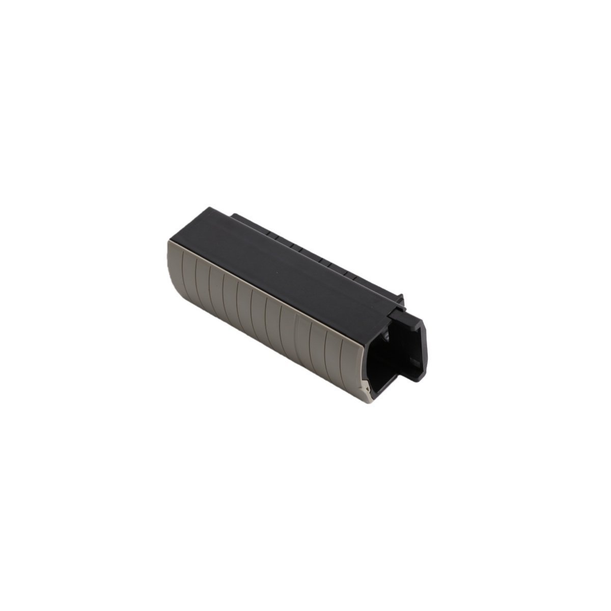
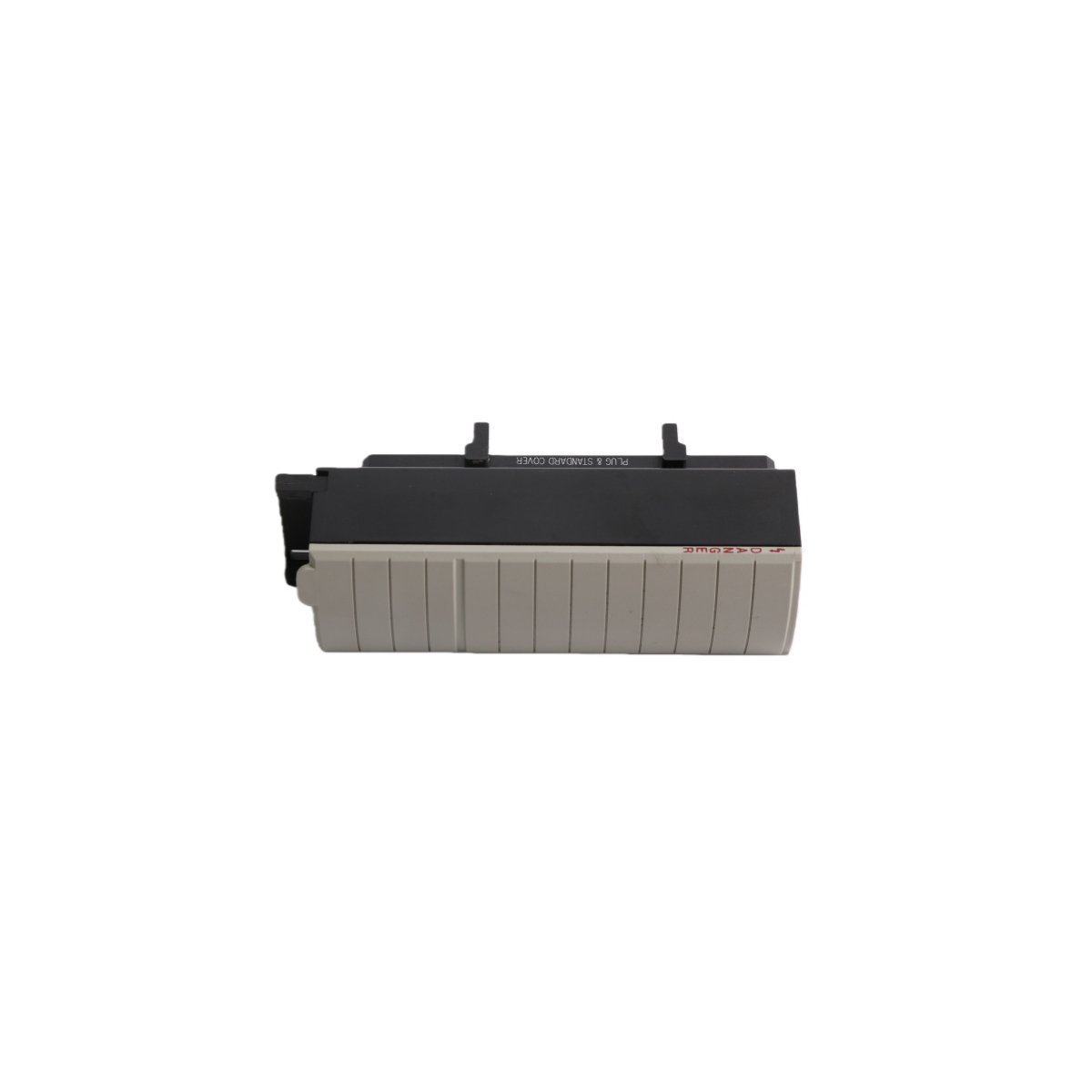
The Allen-Bradley 1756-TBNH is a heavy-duty 20-pin NEMA screw-clamp removable terminal block for ControlLogix I/O field installations. Genuine factory original units are in stock now with expedited worldwide delivery options. Safeguard your automation uptime and wiring integrity today.
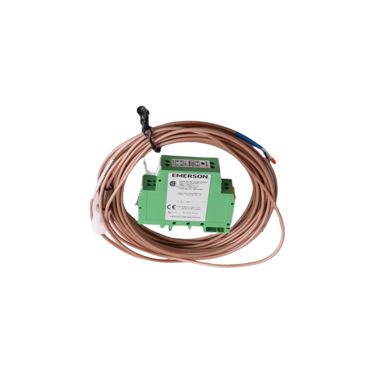
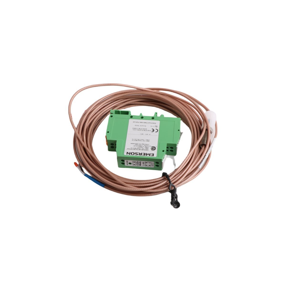
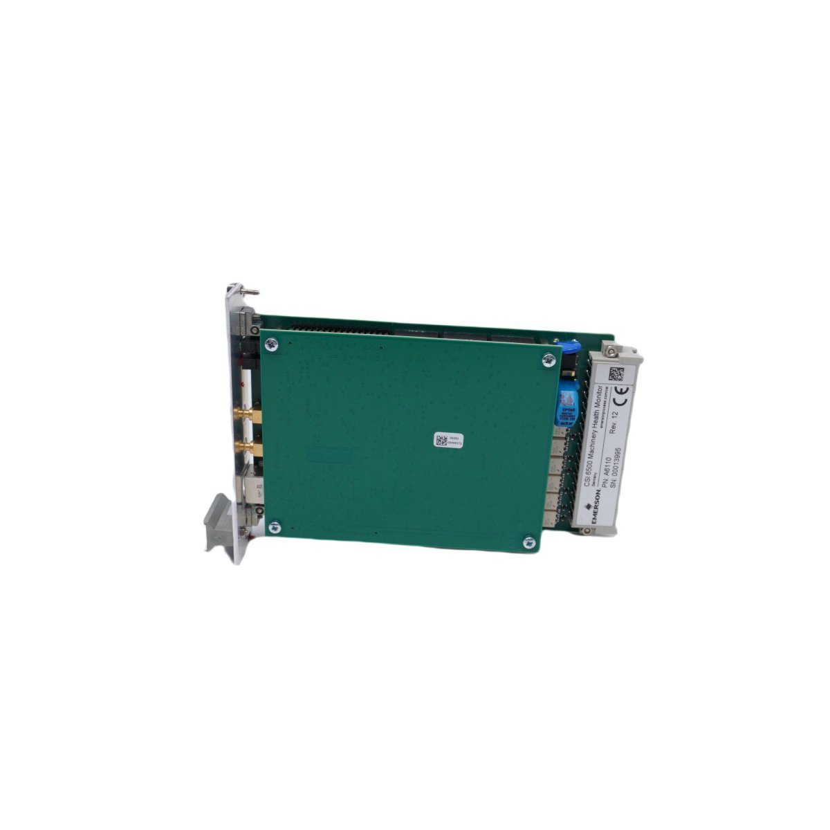
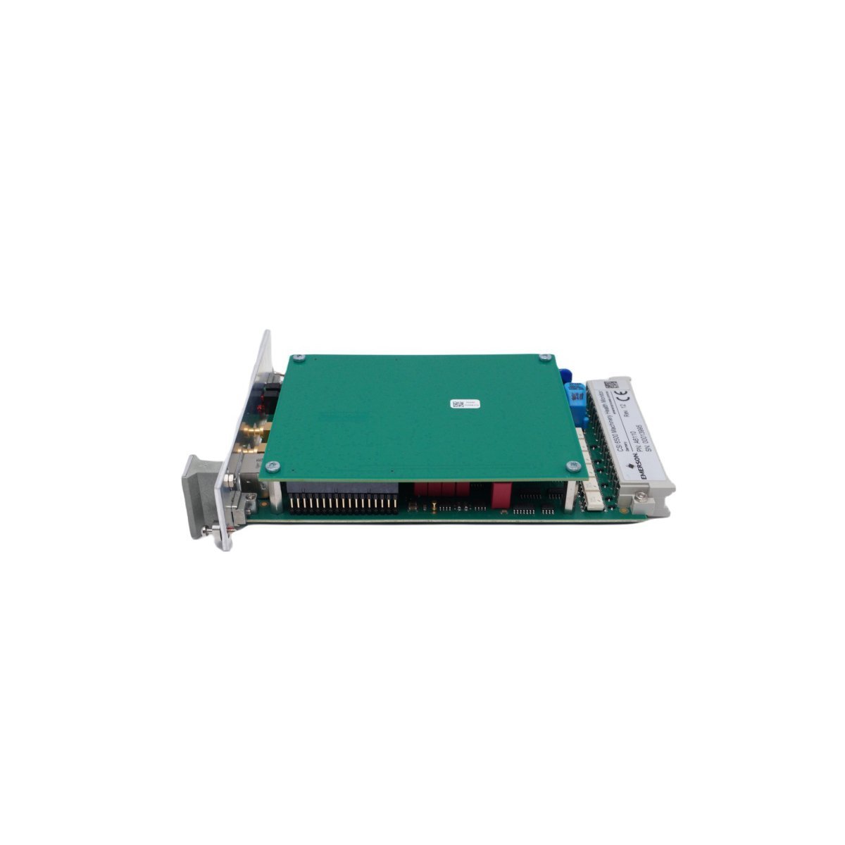
The EMERSON PR6423/00R-131 CON041 is a factory-original eddy current signal converter designed for high-accuracy displacement monitoring. Acquire this brand new, original stock component with secure worldwide shipping options and guaranteed hardware verification. Contact our technical team today to finalize your industrial replacement requirements.
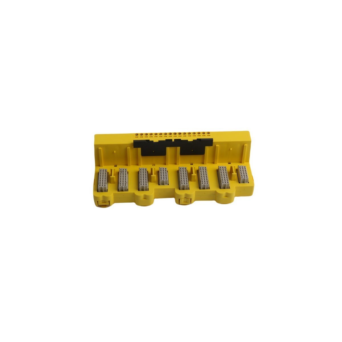
EMERSON KJ2201X1-JA1 12P3323X042 redundant terminal block. Brand New, Original Stock with Global Shipping for high-integrity safety instrumented loops.
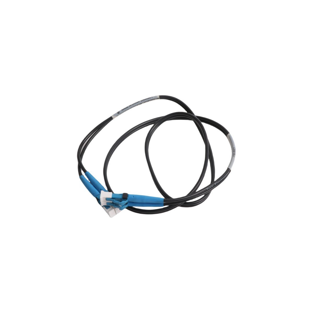
Allen Bradley 1756-RMC1 ControlLogix redundancy link cable. Brand New, Original Stock with Global Shipping for high-availability automated industrial platforms.
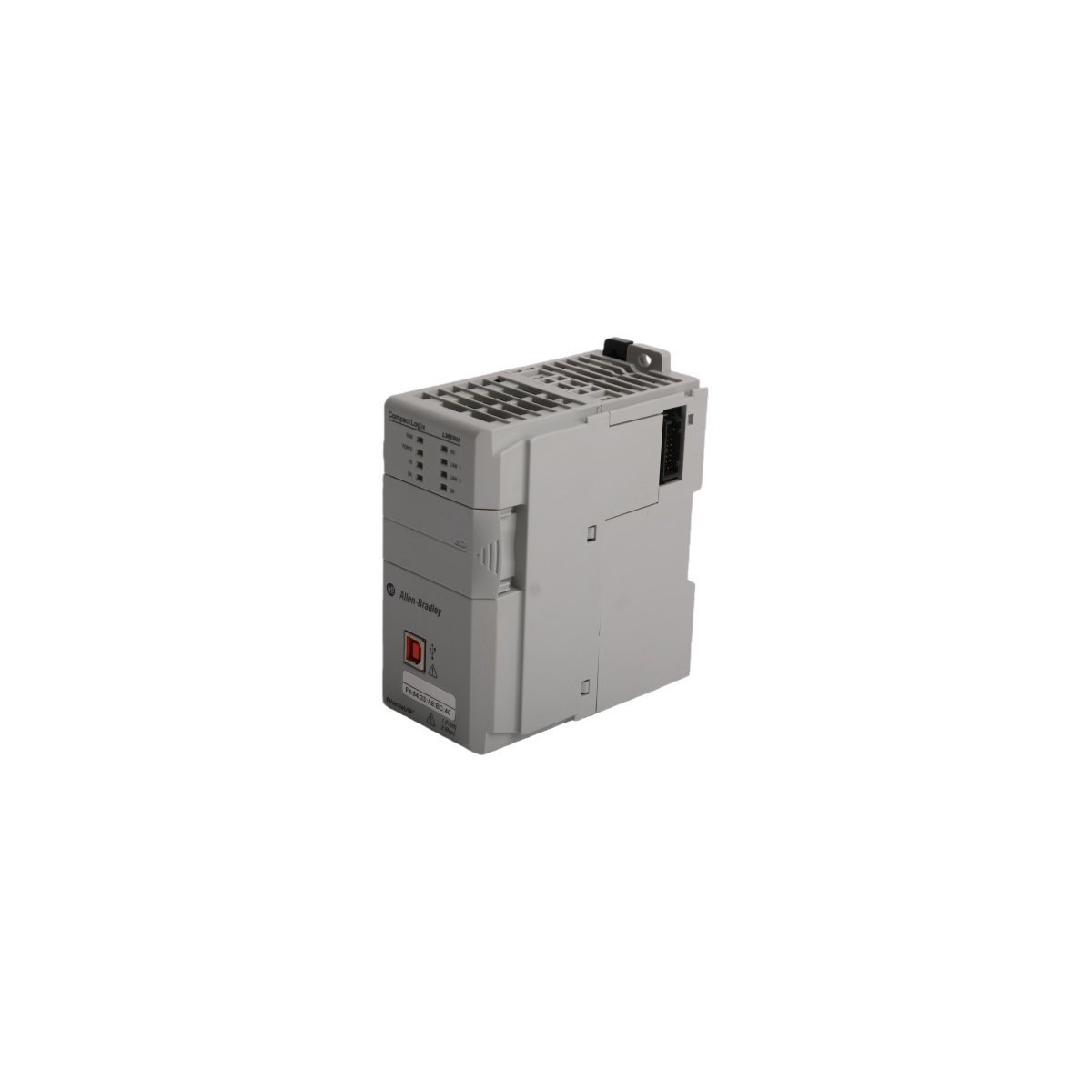
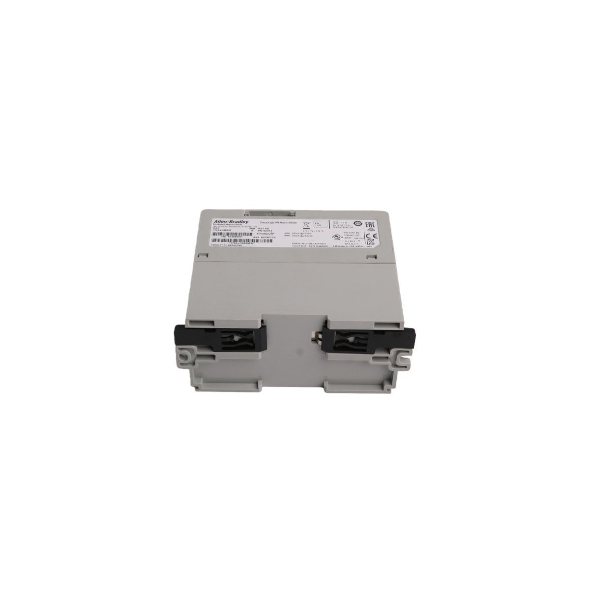
The Allen-Bradley 1769-L36ERM is a CompactLogix 5370 PAC processor featuring 3 MB user memory and 16-axis motion control. Brand New, Original Stock, ready for worldwide distribution.
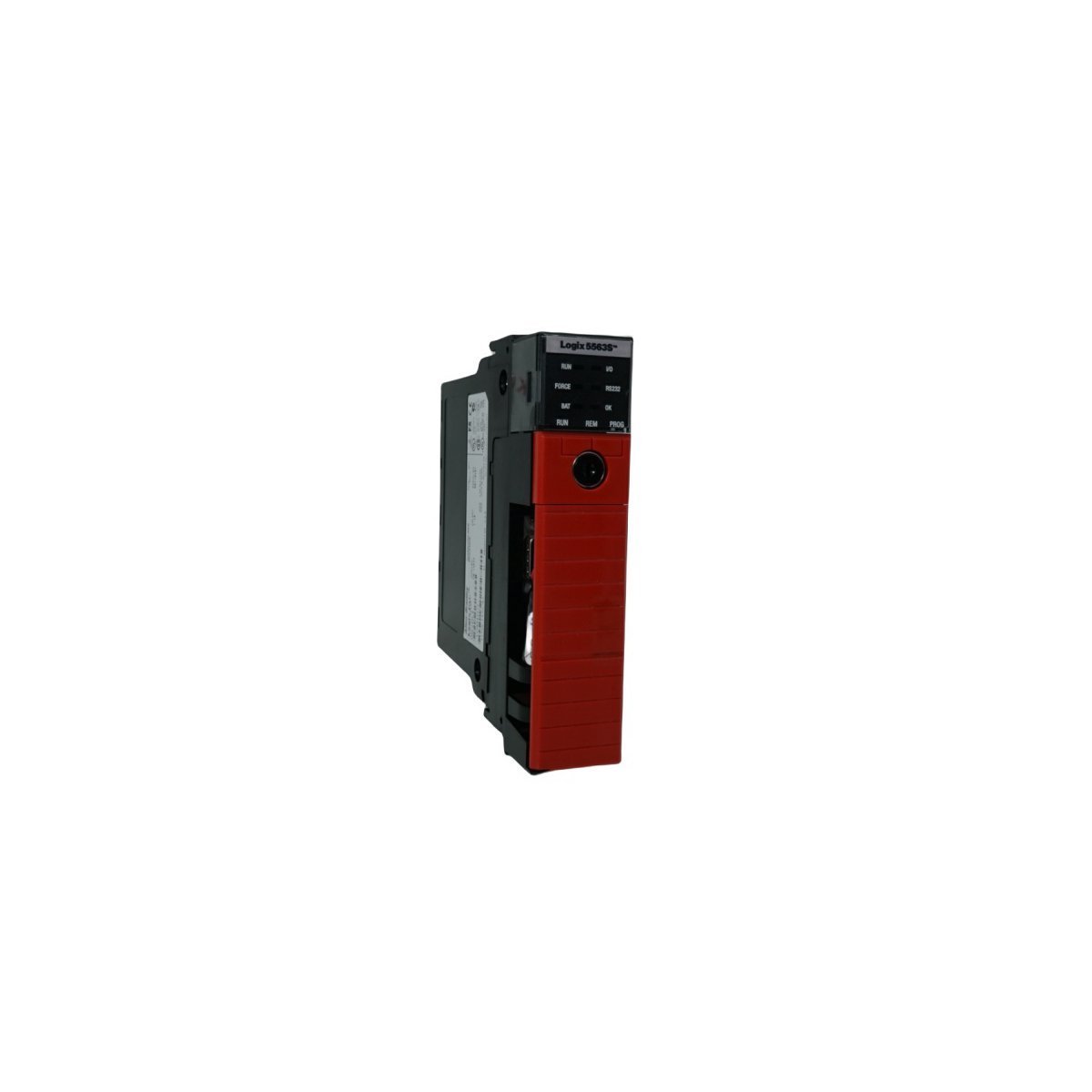
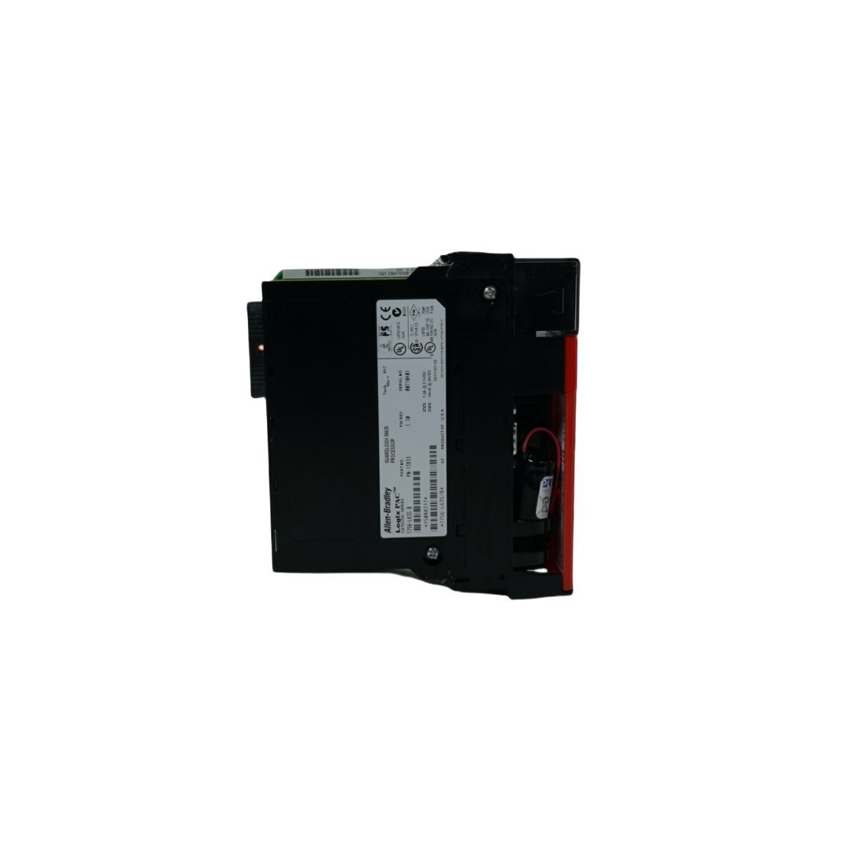
The Allen-Bradley 1756-L63S is a ControlLogix GuardLogix safety controller featuring 8MB user memory. Brand New, Original Stock, available now for global distribution.
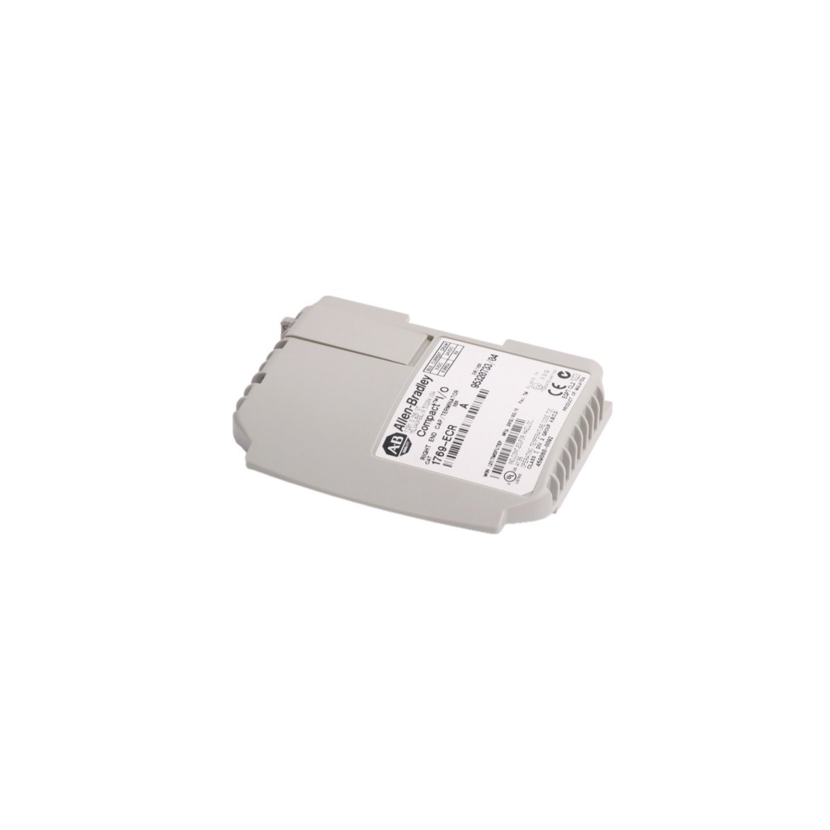
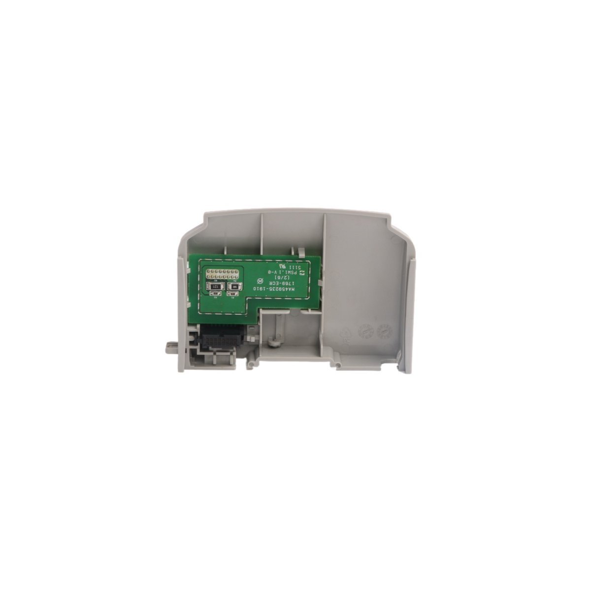
The Allen-Bradley 1769-ECR is a right-side bus termination end cap for CompactLogix and MicroLogix 1500 systems. It terminates the integrated FlexBus backplane to ensure signal integrity, prevent communication packet reflection, and maintain stable PLC operations.
We are committed to protecting your privacy. The information collected here is strictly used to provide the requested quotes, technical support, and relevant industrial automation solutions.