


Sale!
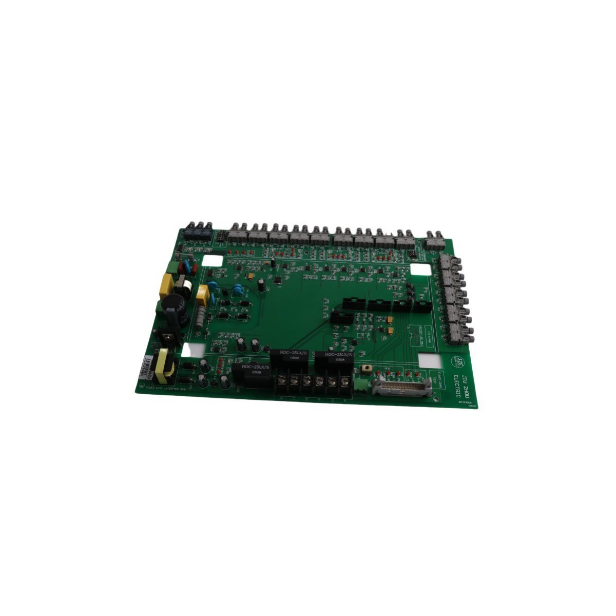
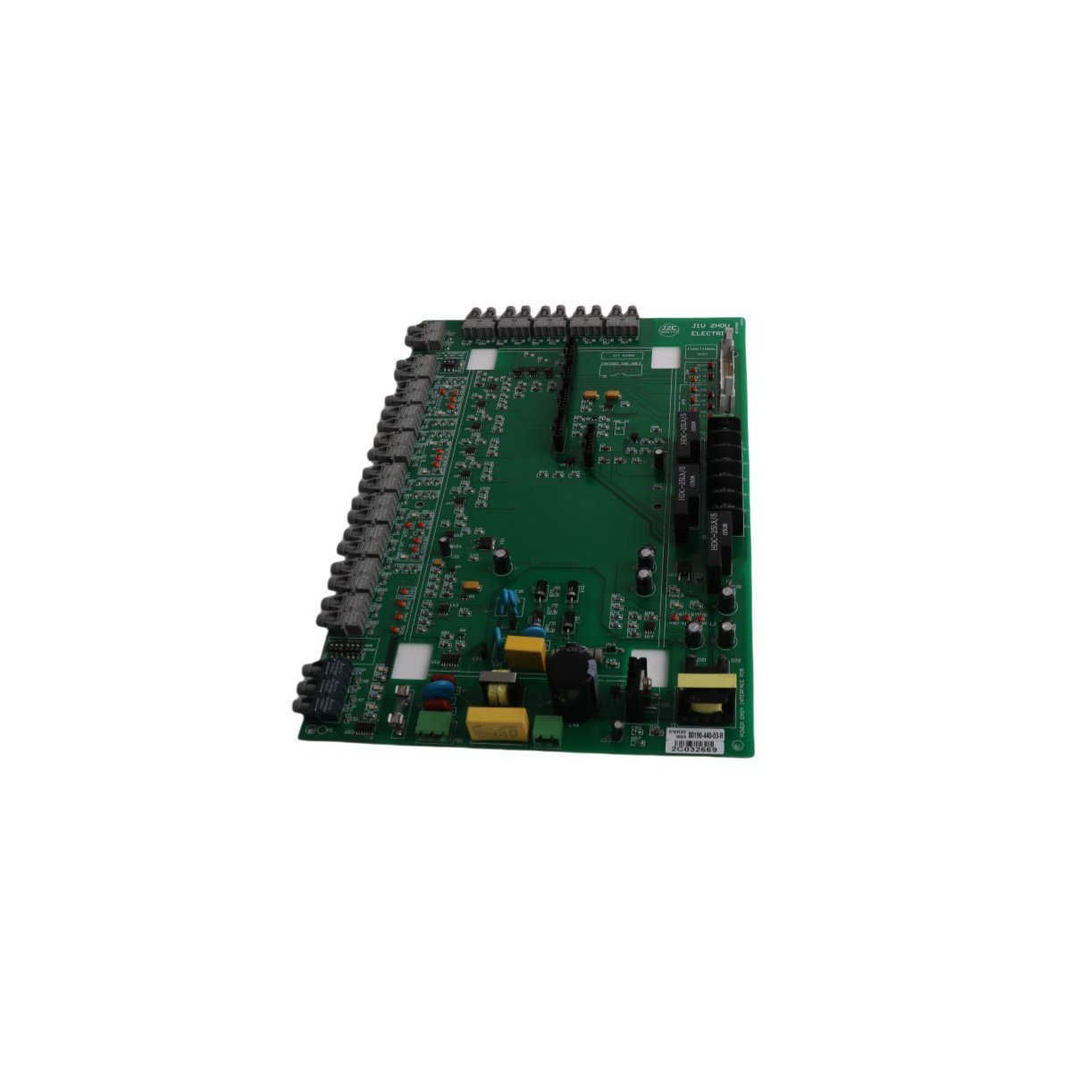
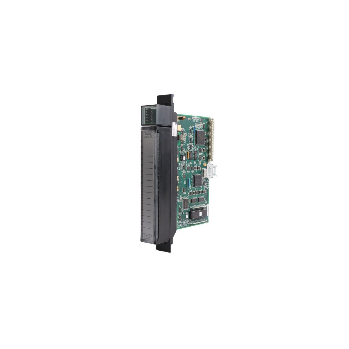
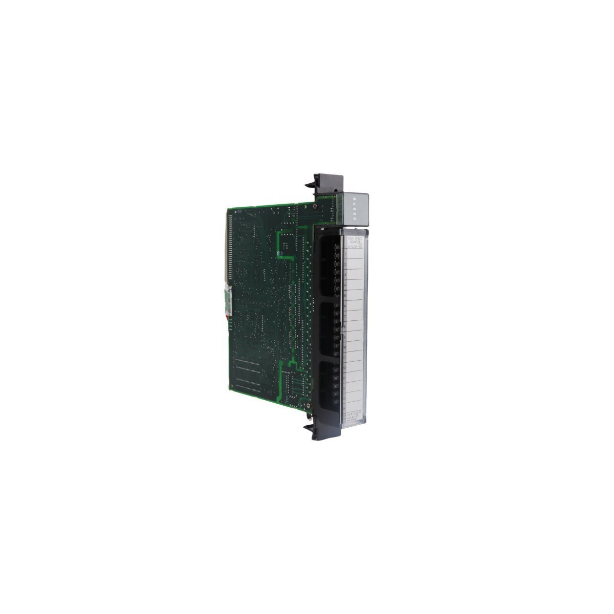
Allen Bradley 80190-440-02-R SMC Flex Interface PCB Module
The Allen Bradley 80190-440-02-R interface board provides reliable signal management and logic control for SMC Flex soft starter motor protection systems.
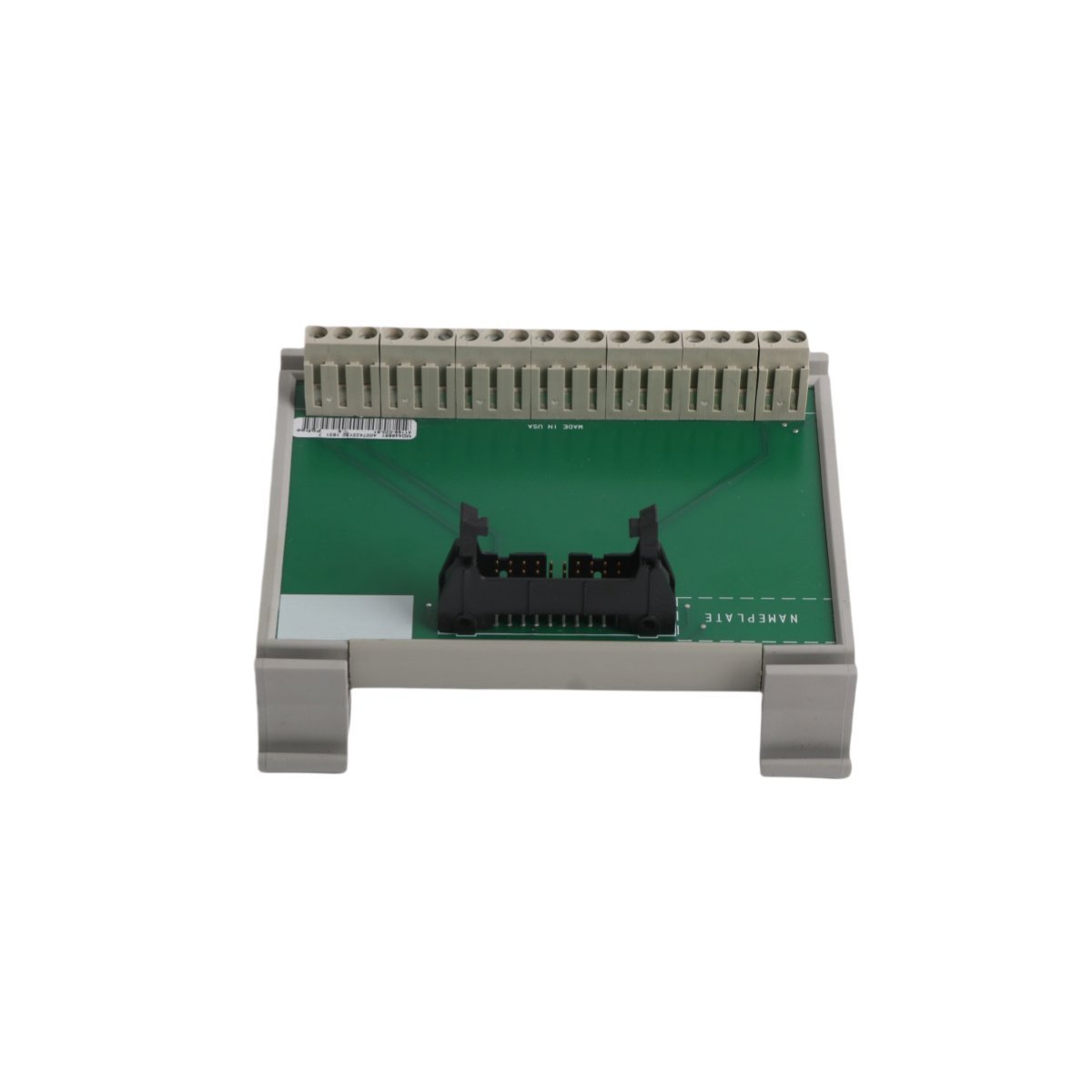
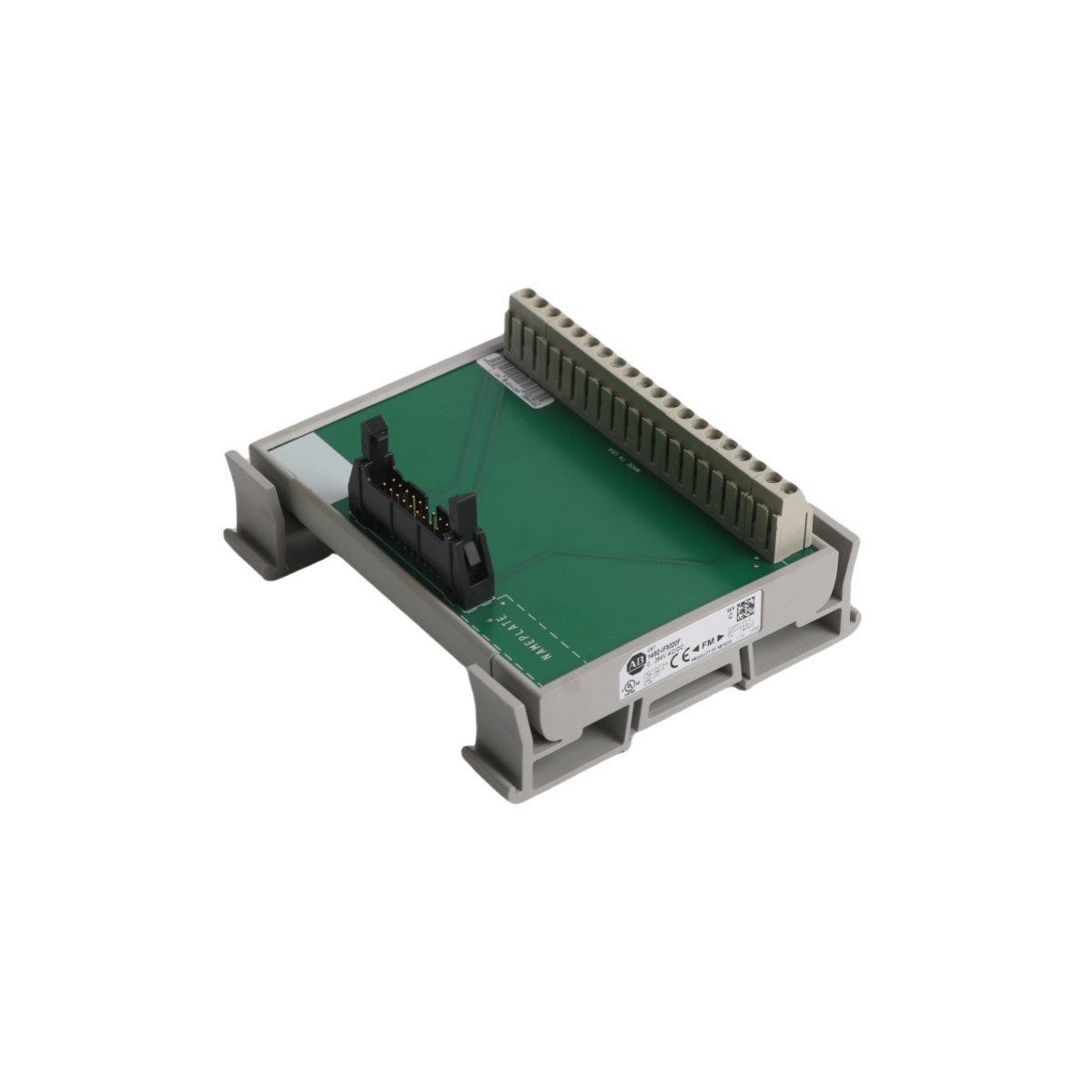
Honeywell FC-PDB-IO05 Power Distribution Board. Brand New, Original Stock. Global Shipping. Safety Manager DCS power module. Order now for immediate dispatch.
The Honeywell FC-PDB-IO05, also cataloged as the FC-PDB-IO05 Power Distribution Board, operates as a dedicated hardware component for power routing within Safety Manager DCS platforms.
| Parameter | Specification |
|---|---|
| Model | FC-PDB-IO05 |
| Brand | Honeywell |
| Origin | USA |
| Weight | 0.45 kg |
| Dimensions | 24 x 18.8 x 6.5 cm |
| Operating Temp | Standard industrial range (consult manual) |
| Power Consumption | Standard backplane draw |
| Module Type | Power Distribution Board |
| System | DCS |
| Condition | Brand New |
This power distribution board supplies regulated power to I/O modules that interface with 4-20 mA HART loop protocol field devices. The board ensures stable power delivery to maintain signal integrity across analog and digital input/output channels. Channel-to-channel isolation is supported through the connected I/O subsystems to prevent ground loop interference. Cold junction compensation (CJC) circuits on connected thermocouple input modules receive stable reference power from this distribution board.
Q: What is the maximum current output per channel on the FC-PDB-IO05? A: The maximum current output per channel is specified in the Honeywell Safety Manager hardware reference manual. Exceeding the rated current per channel may trigger overcurrent protection circuits.
Q: Is the FC-PDB-IO05 hot-swappable during live system operation? A: Hot-swap capability for power distribution boards is not recommended. Power distribution board replacement should only be performed during scheduled maintenance windows with proper system shutdown procedures.
Q: Does this board support redundant power input configurations? A: Redundant power input support depends on the Safety Manager chassis configuration. Consult the system integration documentation for dual-power supply wiring requirements and redundancy switching specifications.
1. Verify the target chassis slot is designated for a power distribution board and confirm all system power is de-energized before installation.
2. Align the board guides with the backplane connectors and apply even pressure until the module seats fully without excessive force.
3. Secure the board using the specified retaining hardware to ensure proper grounding through the chassis and vibration resistance.
4. Connect all power input cables to the designated terminals, verifying correct polarity and torque specifications.
5. Inspect all wiring connections for proper termination and verify no loose conductors before applying system power.

We are committed to protecting your privacy. The information collected here is strictly used to provide the requested quotes, technical support, and relevant industrial automation solutions.