GE IC200PBI001 VersaMax Profibus Network Interface Module
Sale!
SKU: GE Fanuc IC200PBI001
GE IC200PBI001 VersaMax Profibus Network Interface Module
Order the genuine GE IC200PBI001 VersaMax Profibus-DP network interface module from our factory-direct stock. This brand new, fully certified hardware is available with global shipping for immediate remote I/O node integration.
Configured for Profibus-DP fieldbus network interfacing within VersaMax distributed I/O topologies, the GE IC200PBI001 (IC200PBI001 Profibus Network Interface Module) provides direct physical/electrical execution. The hardware operates as a slave network node, mapping cyclic input/output registers from up to 64 local or expanded I/O modules directly into a master host controller’s data tables. It utilizes automated baud rate detection mechanisms to synchronize data transfer rates across physical RS-485 serial communication links without localized software intervention.
Hardware Specifications
Parameter
Specification
Model
IC200PBI001
Brand
GE
Origin
USA
Weight
0.1 kg
Dimensions
8.9 cm x 12.7 cm x 3.2 cm
Operating Temp
0 to 60 deg C
Backplane Power Consumption
250 mA at 5 VDC / 10 mA at 3.3 VDC
Module Type
Profibus Network Interface Unit (NIU)
System Platform
VersaMax I/O System
Supported Protocols
Profibus-DP Slave Mode
Data Rate Range
9.6 Kbaud to 12 Mbaud (Autodetected)
Station Address Range
1 to 125 via integrated rotary switches
Maximum I/O Capacity
375 bytes total per node configuration
Maximum Module Load
Up to 64 functional I/O modules (with expansion racks)
Segment Node Capacity
Up to 32 stations without inline repeaters
Mechanical Mounting
DIN-rail stability matching
Physical Connector
9-pin D-sub female block
Diagnostic Buffers
5 bytes of dedicated user diagnostic data memory
HS Code
8537101190
Backplane Bus Communication Velocity and Deterministic Networks
The network interface module establishes automated data links across the localized backplane bus communication velocity framework, scanning physical terminal parameters sequentially. It maps data payload blocks containing up to 375 bytes of combined discrete and analog input/output states. Serial addresses are adjusted manually using front-accessible rotary switches, binding the hardware node explicitly into Profinet or Profibus deterministic networks. Front panel LED arrays monitor real-time diagnostic parameters, reporting Power, Health, Fault, and active hardware Force states directly to the supervisory bus.
Frequently Asked Questions
Q: How does the network interface handle transmission velocity modifications on the Profibus segment?
A: The hardware contains an integrated baud rate detection circuit that automatically queries and locks onto the master transmission velocity within a range of 9.6 Kbaud up to 12 Mbaud upon bus initialization.
Q: What precautions must be taken when executing a firmware flash modification?
A: Prior to commencing a firmware update via the local serial link, the supervisor must place the master controller into stop mode and physically disconnect the upstream Profibus network cable from the D-sub interface.
Q: Is a dedicated carrier required to supply internal voltage logic to the interface card?
A: Yes. The module receives logic operational current through a matching VersaMax power supply module mated directly to the unit layout via localized mechanical interlock latches.
Field Installation Guidelines
DIN-Rail Mounting Stability: Snap the module assembly firmly onto standard 35 mm DIN rails. Ensure the integrated ground spring establishes a low-impedance connection with a clean, unpainted surface on the metal rail structure.
Rotary Address Adjustments: Use a calibrated flat screwdriver to set the network node address via the decimal rotary switches within the valid 1 to 125 sequence prior to applying power to the backplane.
DB9 Connection Shielding: Secure the Profibus cable assembly using a shielded 9-pin D-sub connector housing. Ensure the outer cable braid makes complete electrical contact with the metallic connector body to block common-mode noise.
Bus Termination Resistance: When positioning this hardware as the first or last active station on a network branch, ensure the termination switch on the external DB9 connector is toggled to the “ON” state.
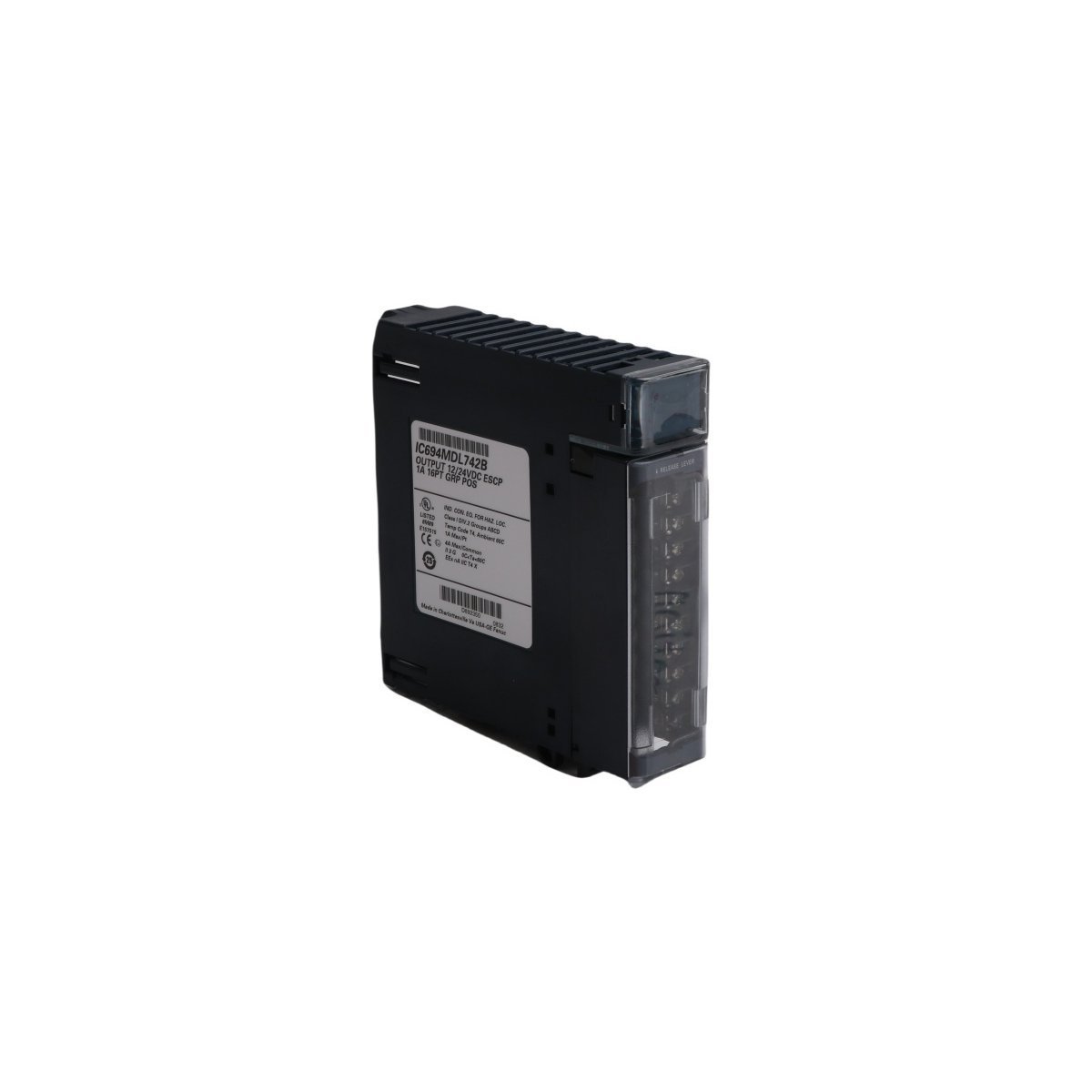
Purchase the genuine GE IC694MDL742 PACSystems RX3i discrete sinking voltage output module. Available in brand new original stock condition with global shipping availability. Contact technical support to secure fully tested industrial control hardware.
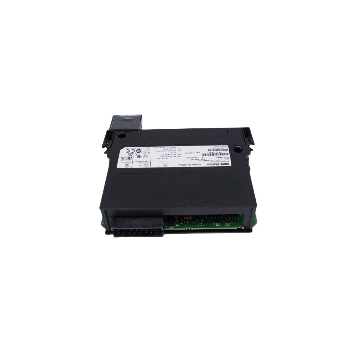
Get the genuine Allen-Bradley 1756-OB16E ControlLogix Discrete Output Module featuring 16 electronically fused points and 24 VDC sourcing outputs. Discontinued Spare, Original Surplus with Global Shipping. Minimize automation downtime now.
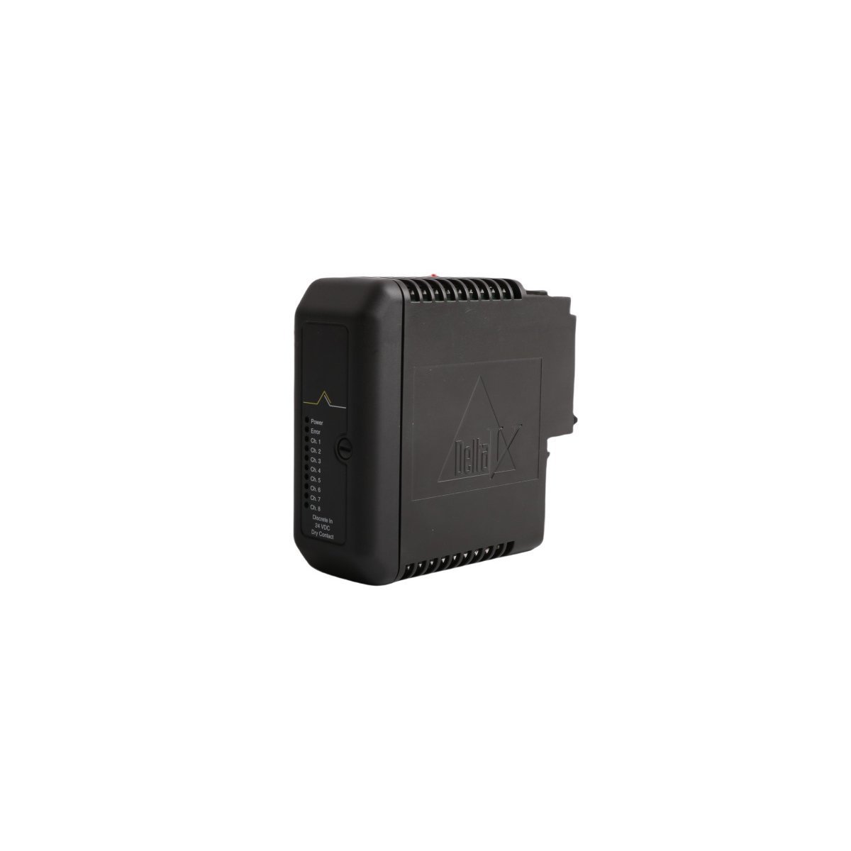
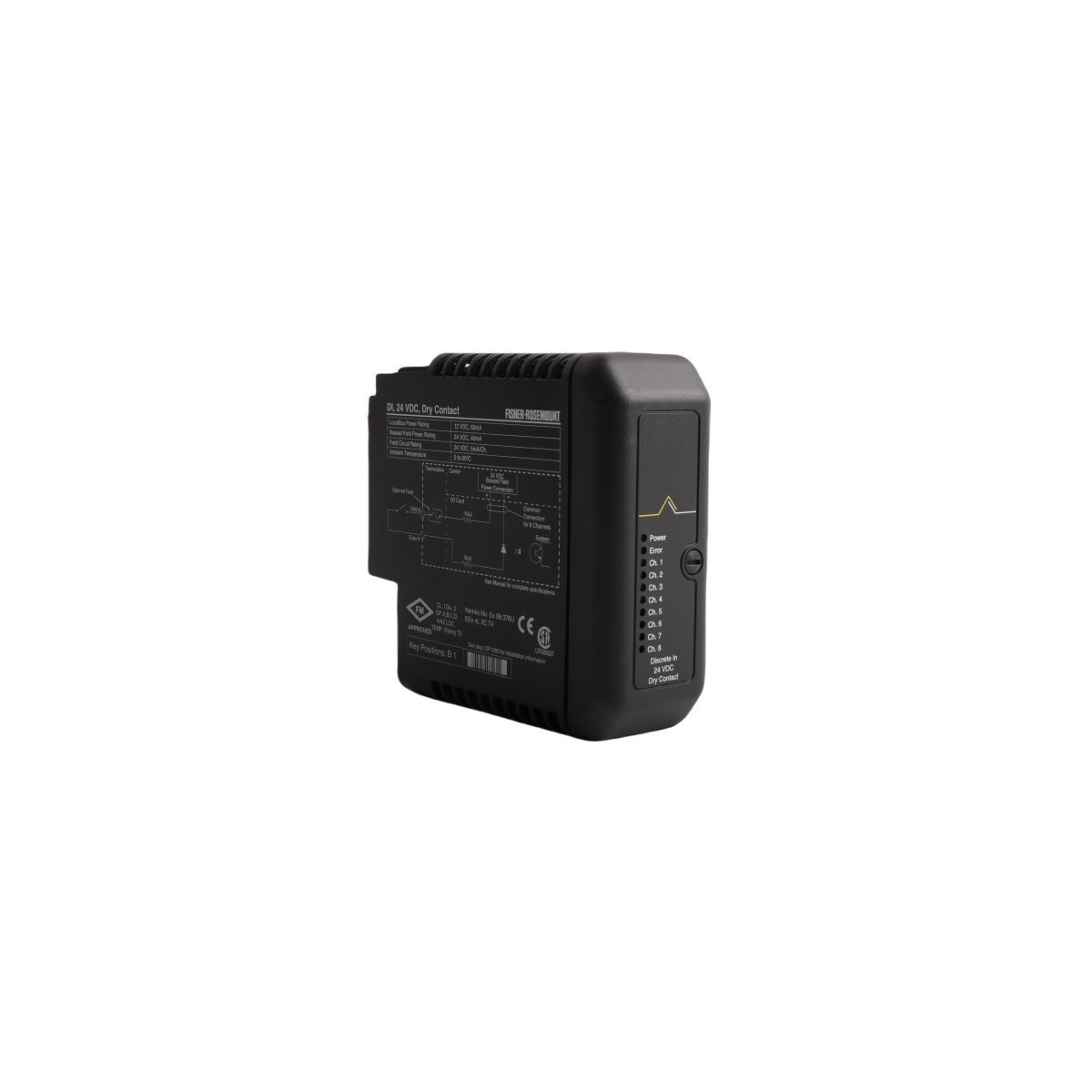
Secure the EMERSON KJ3001X1-BB1 12P0550X142 Dry Contact Module for your DeltaV SIS. Brand New, Original Stock, factory-direct spare ready for Global Shipping. Maximize your DCS runtime—Request an instant quote today.
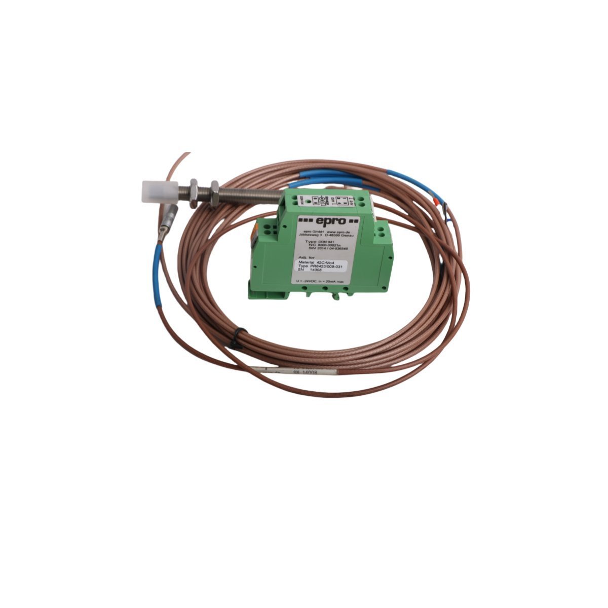
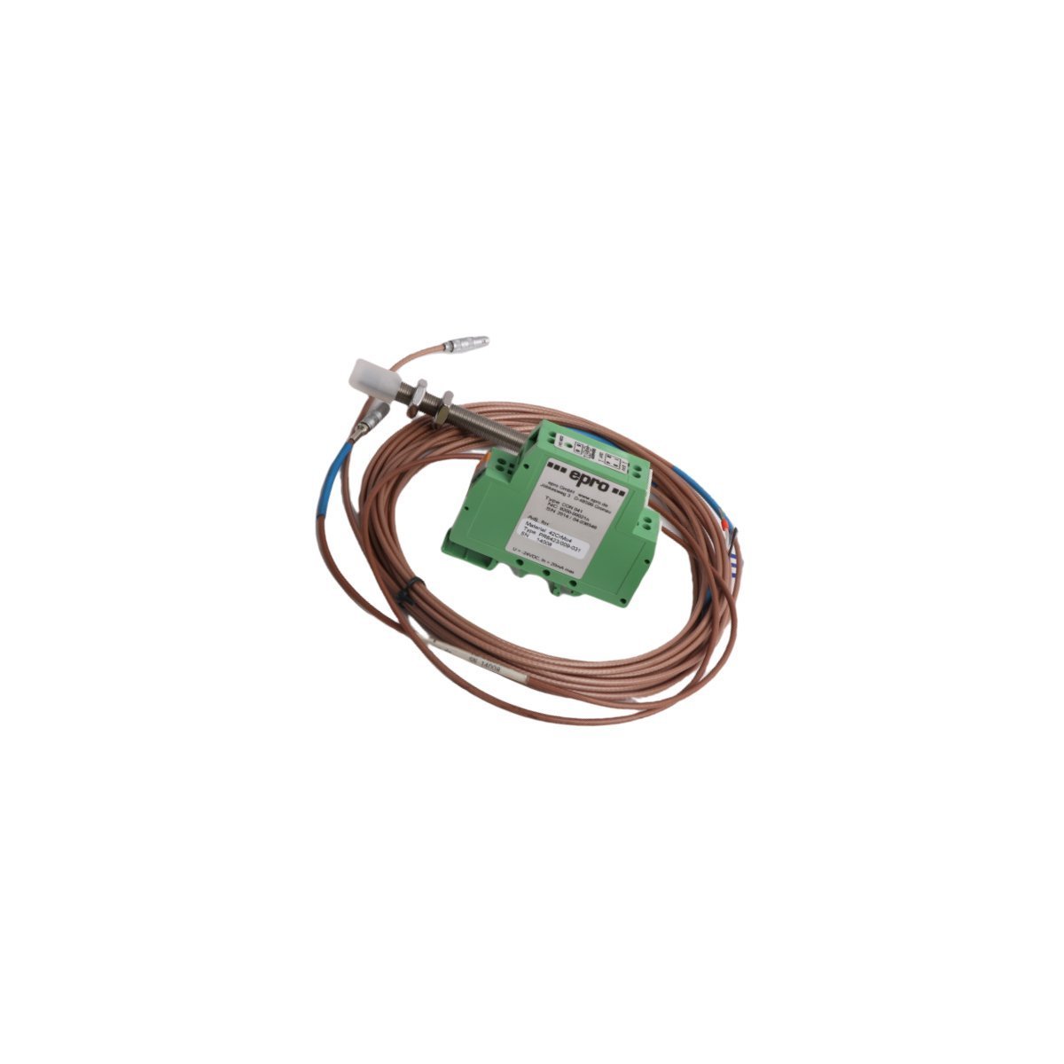
The EMERSON PR6423/009-031 CON041 delivers stable eddy-current transformation for shaft dynamic tracking. Brand New, Original Stock, fully certified with Global Shipping. Minimize critical machine downtime—Request a quote now.
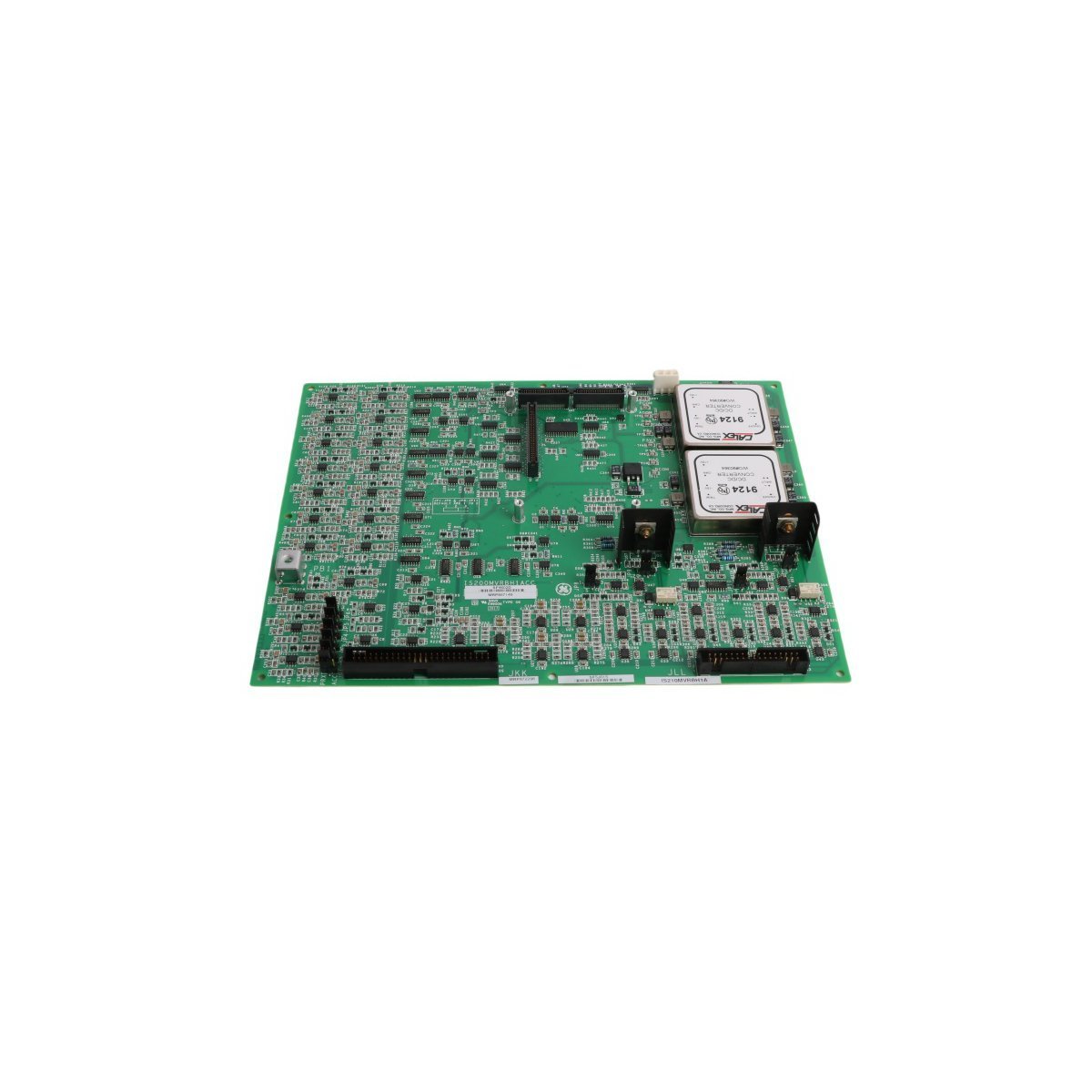
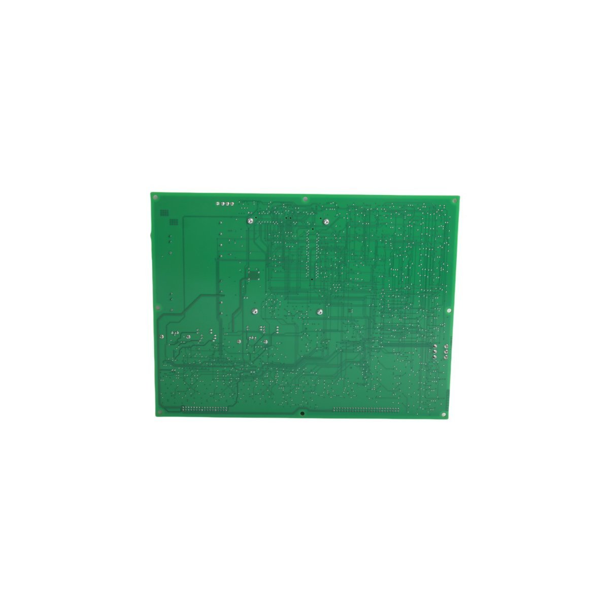
The GE IS210MVRBH1A is a high-accuracy I/O interface board for Mark VIe systems. It supports R/S/T signal processing, real-time thermal monitoring, and IONet connectivity.
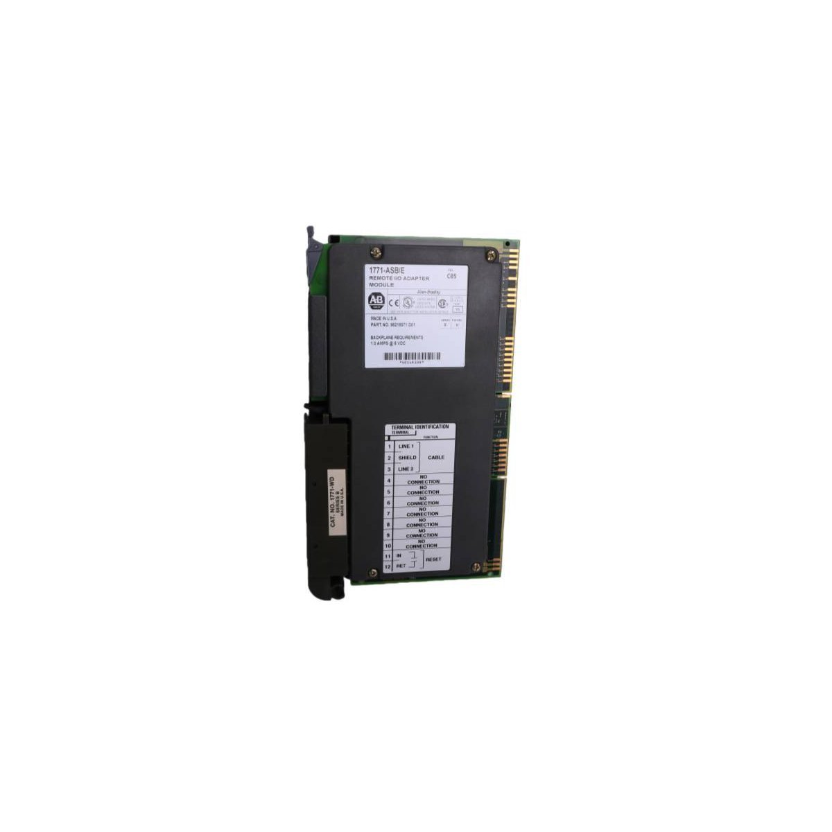
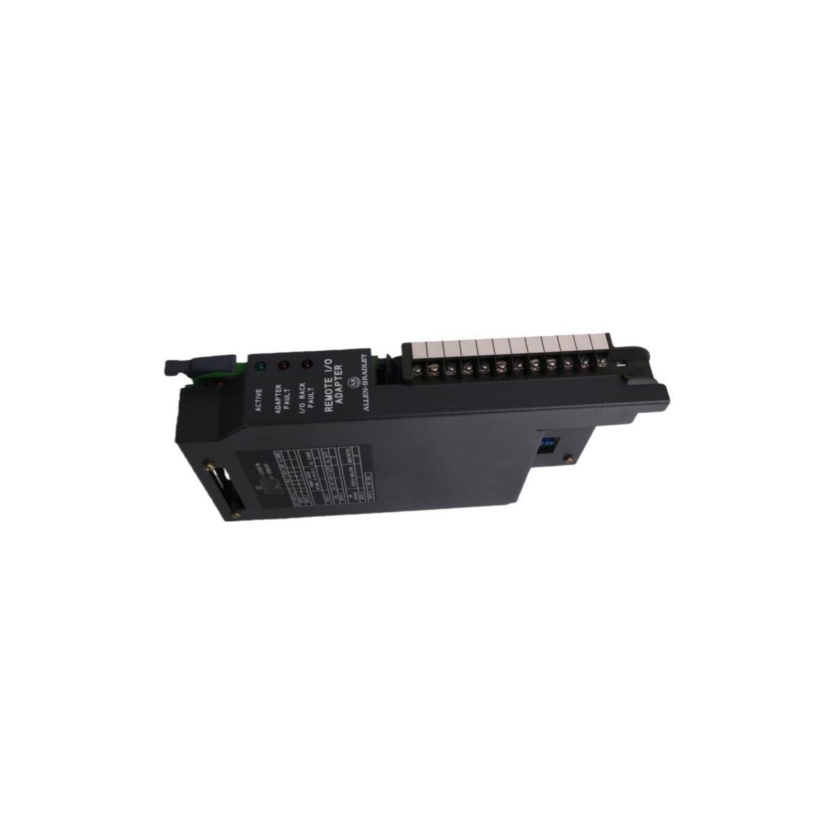
The Allen-Bradley 1771-ASB/E is a universal Remote I/O adapter module for PLC-5 systems, designed to enable efficient distributed I/O communication and diagnostics.
The Allen-Bradley 80190-600-01-R is an industrial optical interface base circuit board. Brand New, Original Stock, Global Shipping available for immediate deployment.
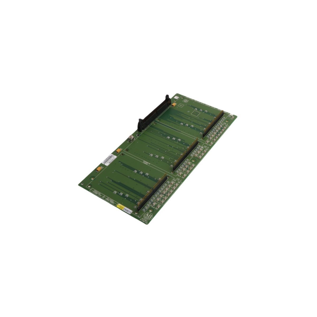
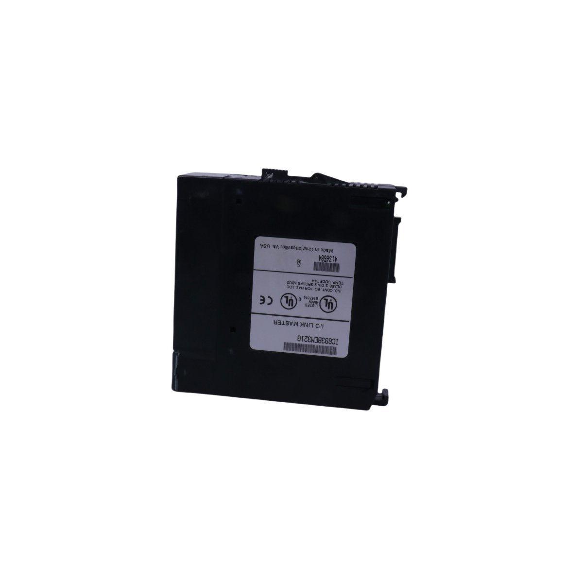
The GE Fanuc IC693BEM321 is a Series 90-30 I/O Link Master Module designed to control up to 16 slave devices. It supports 1024 I/O points and utilizes RS-422/RS-485 protocols for high-speed, reliable remote communication in complex automation environments.
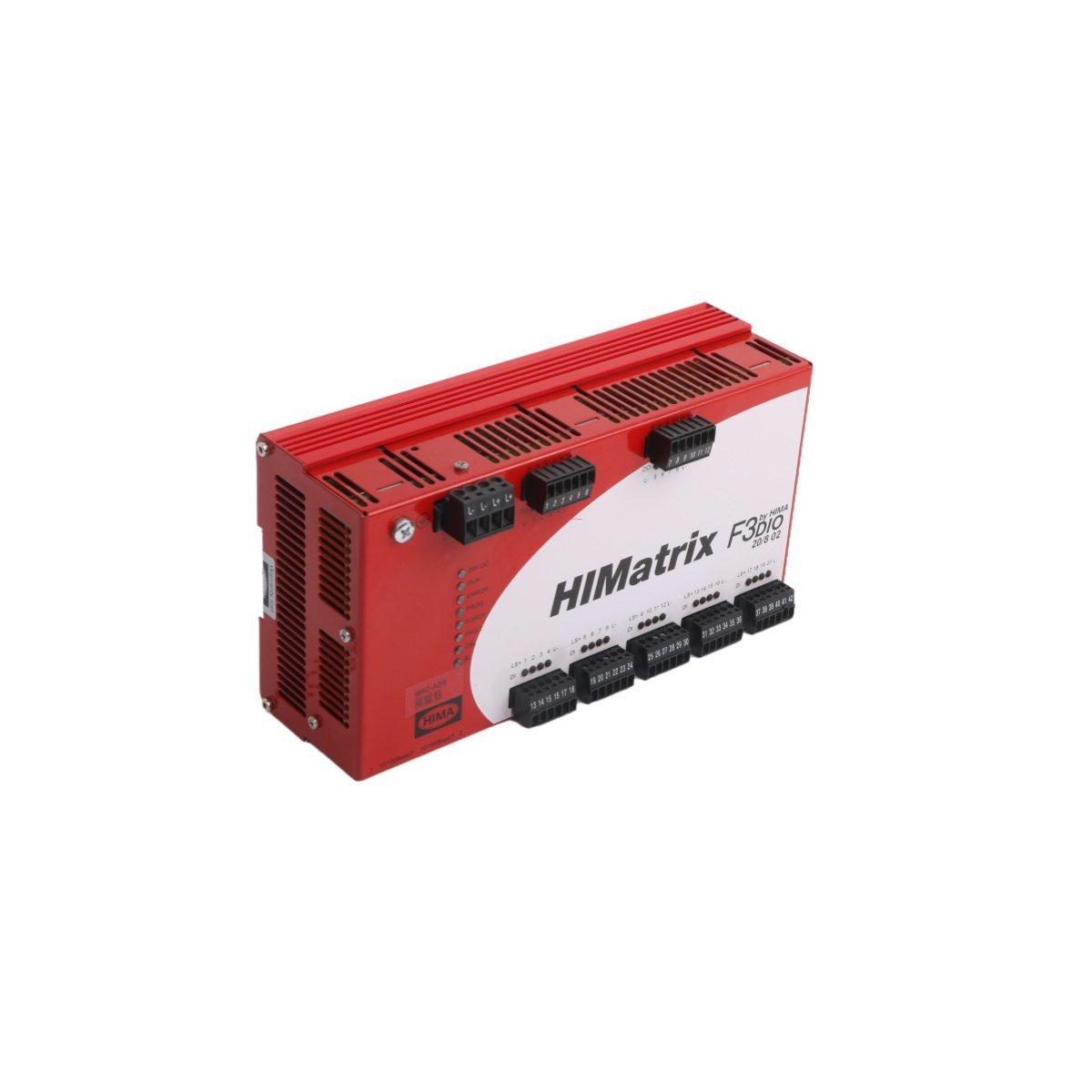
The HIMA HIMatrix F3DIO20/802 is a SIL 3-certified Remote I/O Module featuring 20 digital inputs and 8 digital outputs. Designed for decentralized safety-related automation, this module ensures high-speed data transmission over Ethernet with maximum fault tolerance. It provides a robust, German-engineered solution for emergency shutdown and process safety applications in harsh industrial environments.
The ICS Triplex T3491 is a high-performance Multiplexed I/O Module designed for the Regent Control System. It provides fault-tolerant analog signal processing and integrated diagnostics for safety-critical PLC applications. This brand-new, USA-made module features an 1.82 kg robust build and Ethernet router service capabilities to ensure seamless industrial automation connectivity.
The GE IS220YPROS1A is a high-speed backup protection I/O module designed for the Mark VIe control system. It provides critical overspeed monitoring and emergency shutdown logic for turbines, featuring dual-port redundancy and TMR capabilities to ensure maximum power plant safety and reliability.
The Emerson KJ3221X1-BA1 (VE4003S2B2) is a 32-channel, 24VDC discrete output module for DeltaV S-series systems. Featuring advanced loop diagnostics, high-density switching, and hot-swap capability, this module provides reliable and fault-tolerant control for solenoid valves and relays in demanding process environments.
We are committed to protecting your privacy. The information collected here is strictly used to provide the requested quotes, technical support, and relevant industrial automation solutions.