Sale!
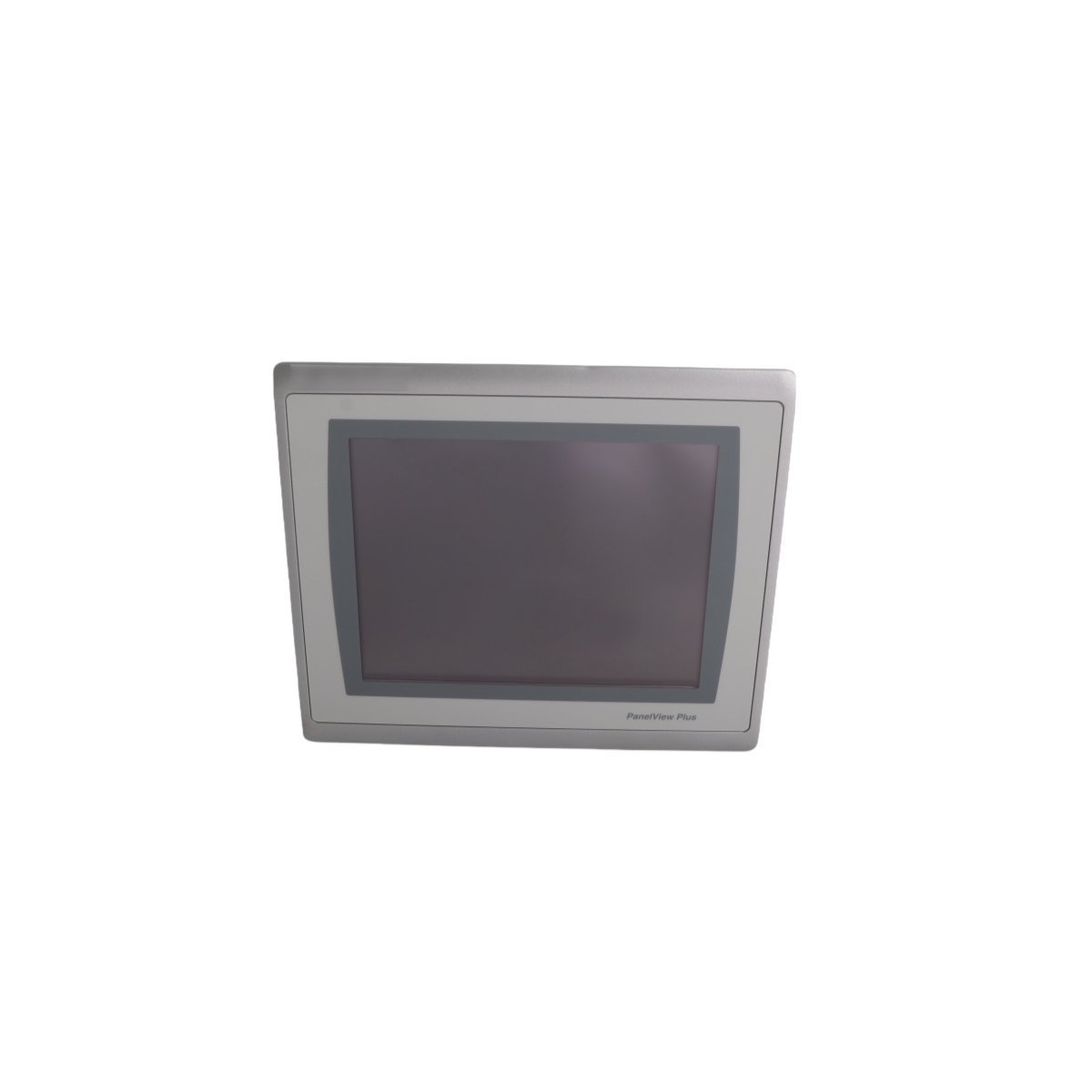
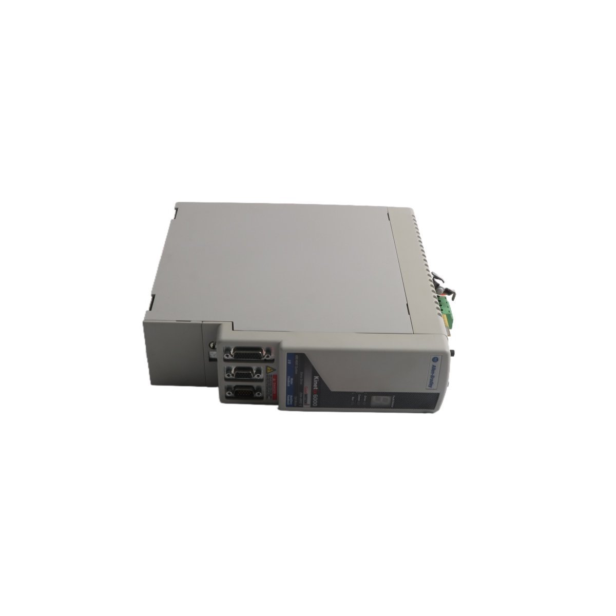
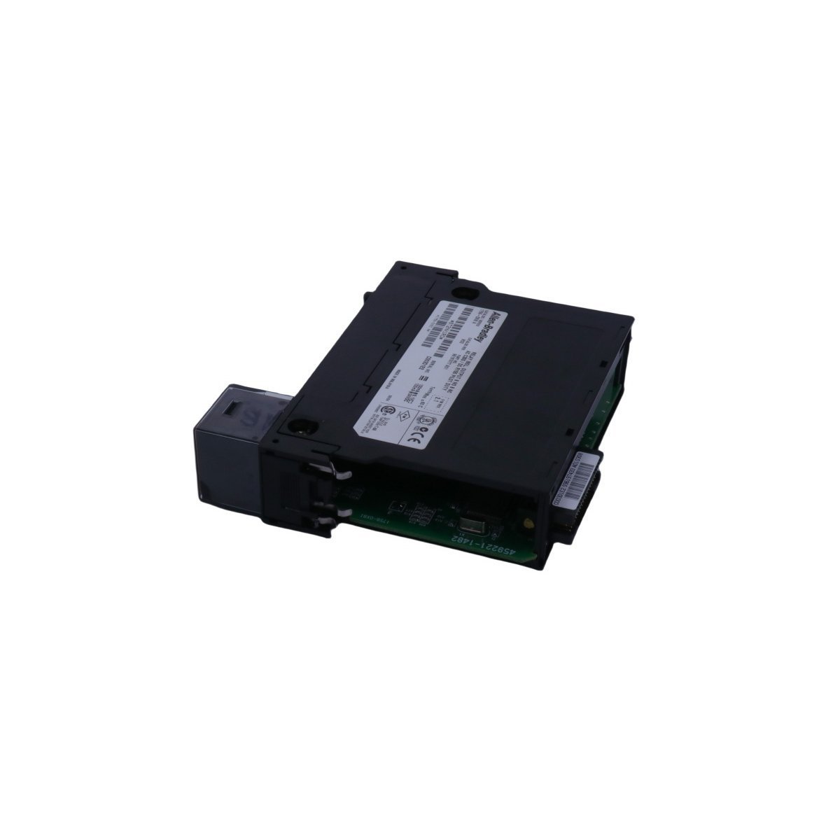
Allen-Bradley 2711P-T10C22D9P PanelView Plus 7 Terminal
The Allen-Bradley 2711P-T10C22D9P serves as the primary 2711P-T10C22D9P PanelView Plus 7 Standard Color Terminal utilized to execute human-machine interface (HMI) visualization tasks across ControlLogix and CompactLogix platforms. Configured for direct panel monitoring and physical touch input control, the unit provides real-time graphic execution of process variables over local network nodes.
Hardware Specifications
| Parameter | Specification |
|---|---|
| Model | 2711P-T10C22D9P |
| Brand | Allen-Bradley / Rockwell Automation |
| Origin | USA |
| Weight | 0.9 kg (Net) / 2.3 kg (Packaged) |
| Dimensions | 3.5 x 13 x 14.5 cm (Chassis depth/profile variation) |
| Operating Temp | 0 to +55 deg C |
| Power Input | 24 VDC (PELV/SELV compliant) |
| Power Consumption | 50 W maximum |
| Display Type | 10.4-inch Color TFT (800 x 600 SVGA) |
| Memory | 512 MB RAM / 80 MB Non-volatile user storage |
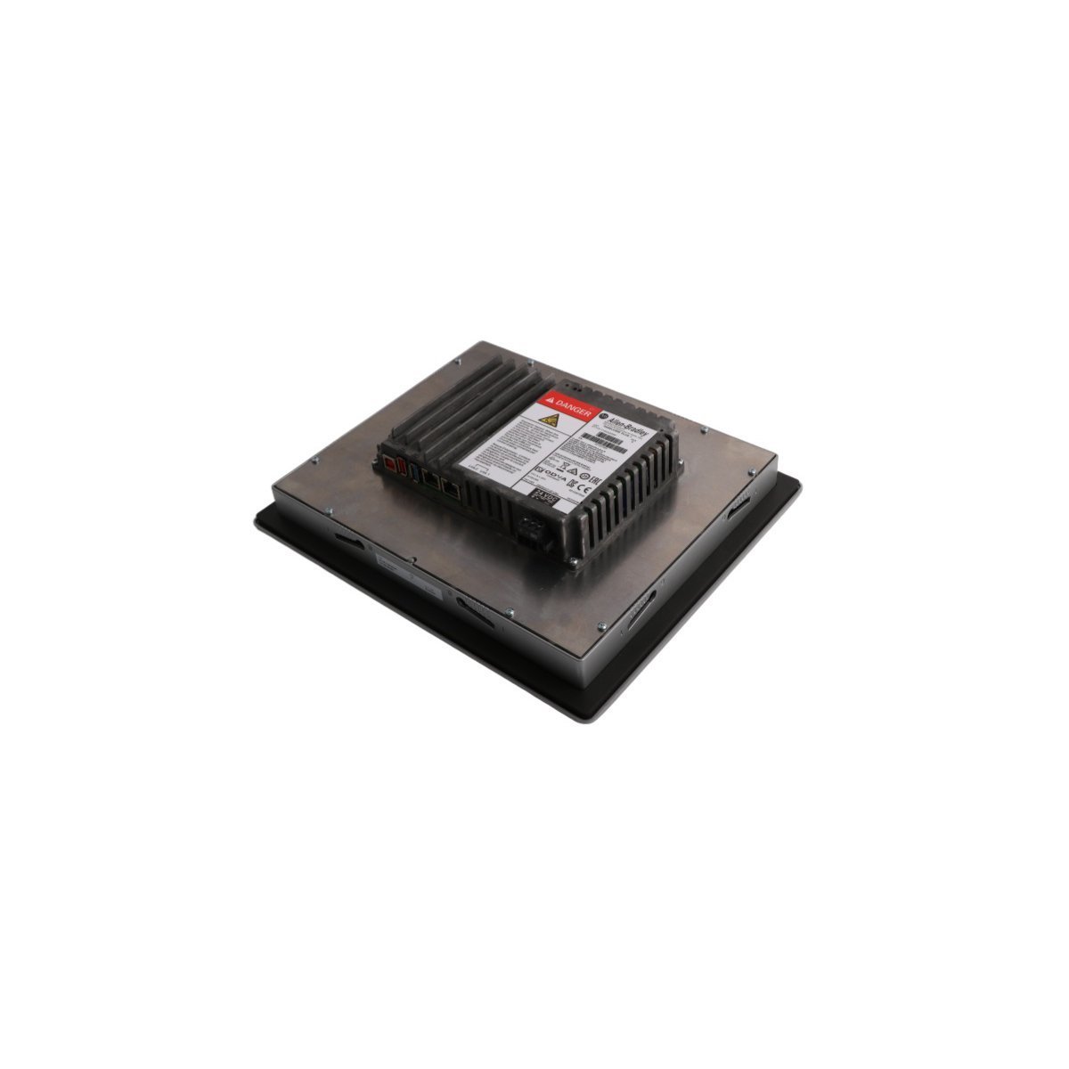
| Communication Ports | Dual 10/100 Base-T Ethernet (DLR), USB ports |
| Discontinued Date | June 30, 2016 (Catalog data reference) |
Deterministic Network Routing & I/O Density Scaling
The HMI assembly utilizes integrated dual Ethernet ports configured for Profinet / EtherNet/IP deterministic networks, supporting Device Level Ring (DLR), linear, and star network topologies directly at the machine layer. This eliminates the necessity for external switches while protecting communication velocity against single-point physical cable breaks.Internal memory constraints control runtime graphic caching, allowing scaling for dense register structures mapped from local programmable automation controllers. Device settings and operational runtime parameters are updated via standard firmware flash compatibility tools or through FactoryTalk View Studio Machine Edition configuration routines.Frequently Asked Questions
Q: What are the dual Ethernet port operational constraints regarding separate IP subnets?A: The integrated dual ports function as an embedded switch node supporting Device Level Ring (DLR) topology. Both physical interfaces share a single IP address and cannot be partitioned to bridge separate, independent subnets.Q: How is application data retention managed if primary 24 VDC input power is lost?A: The terminal utilizes onboard non-volatile flash memory to store the compiled runtime (.mer) application project file. System parameters and historical log data are committed directly to internal solid-state registers, removing battery dependency for file preservation.Field Installation Guidelines
- Enclosure Cutout Positioning: Prepare the panel door cutout using exact engineering template metrics. Ensure the surrounding sheet metal remains flat and free of distortion to establish uniform compression against the sealing gasket.
- Torque Adjustments for Mounting Clips: Tighten the supplied panel mounting levers evenly in an alternating sequence. Do not exceed specified torque limits to avoid cracking the plastic bezel or compromise the NEMA/IP environmental seal.
- Grounding Requirements: Connect the functional earth terminal on the rear power input connector block to a low-impedance master enclosure ground bar using a dedicated, short copper wire.
- External Storage Handling: Insert or extract approved external memory cards only when the execution engine is idle to prevent database structure corruption within historical trending folders.