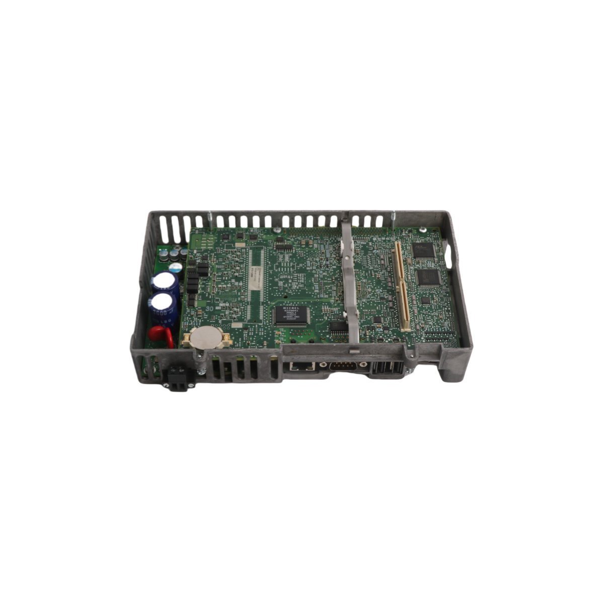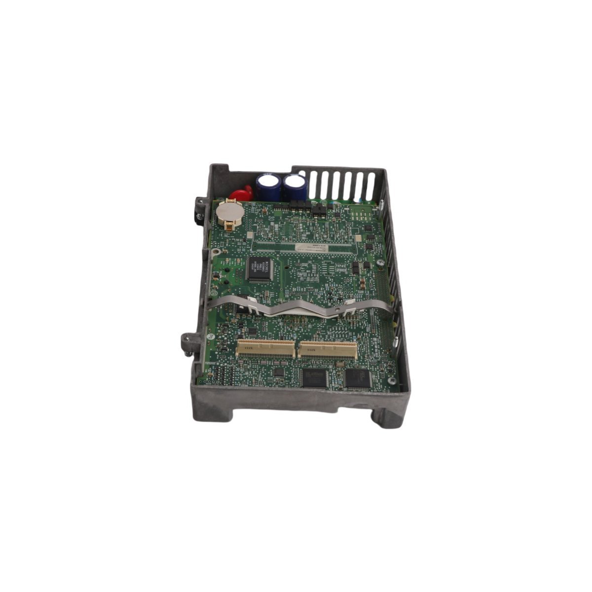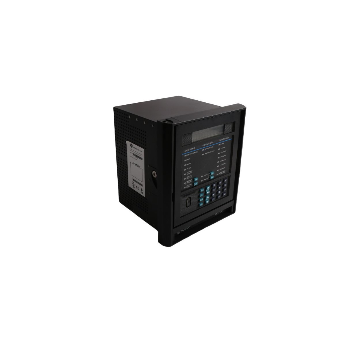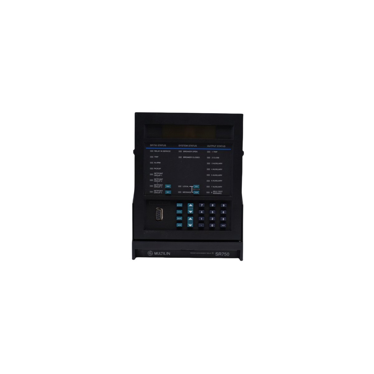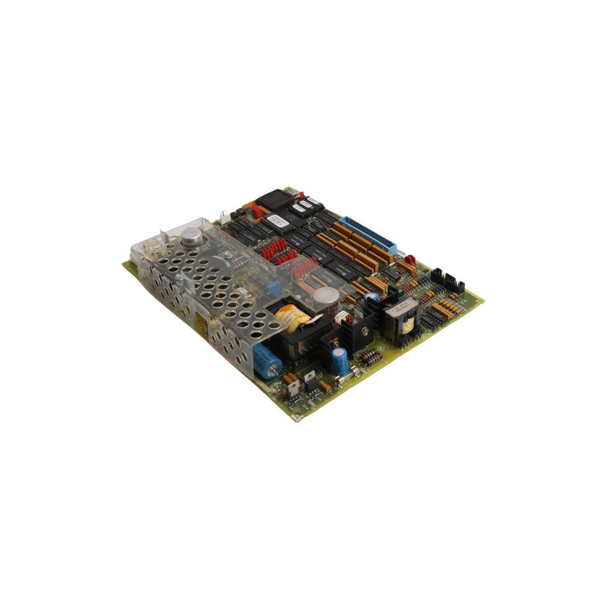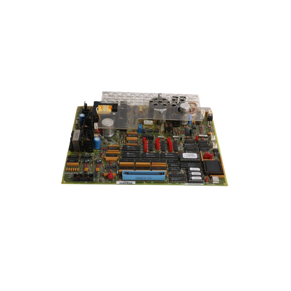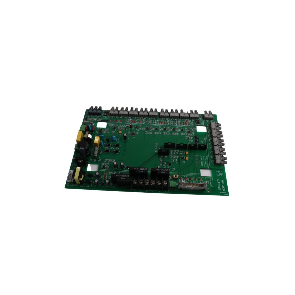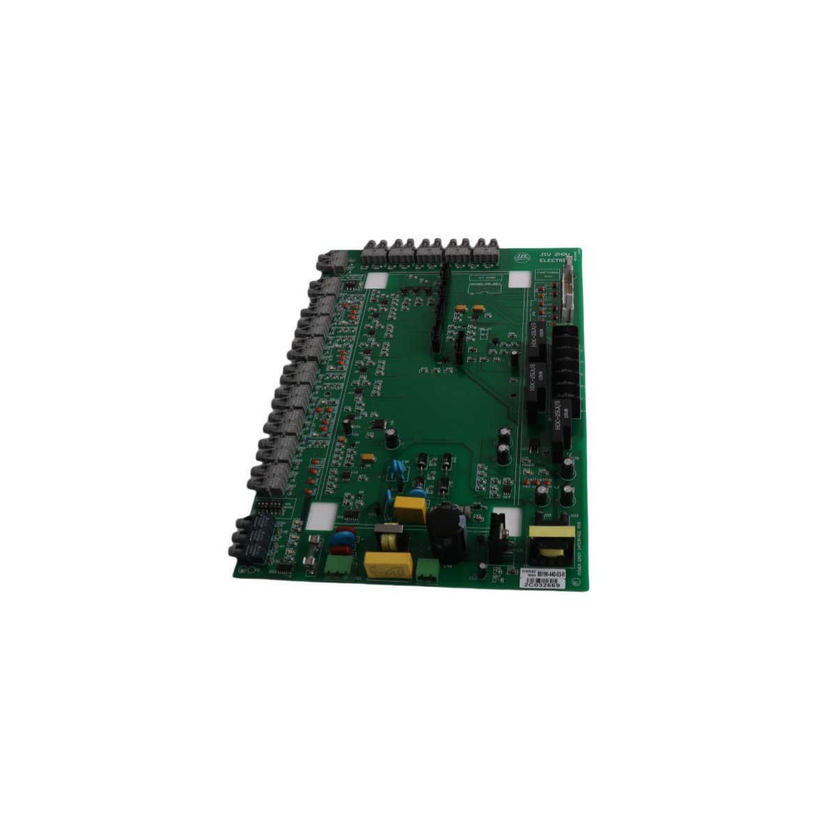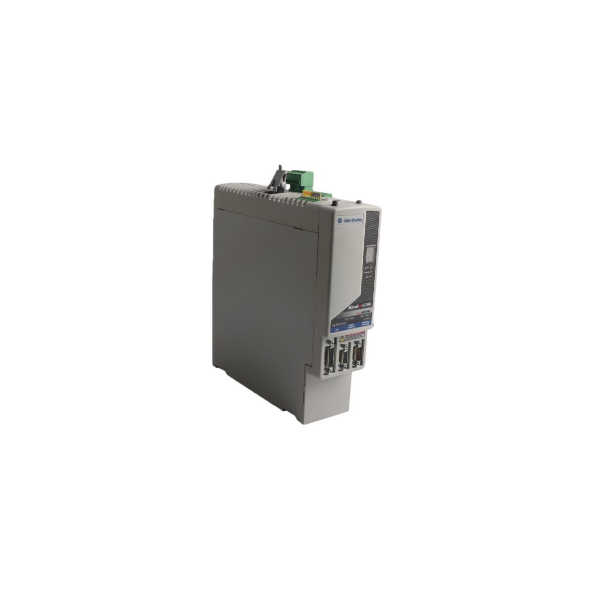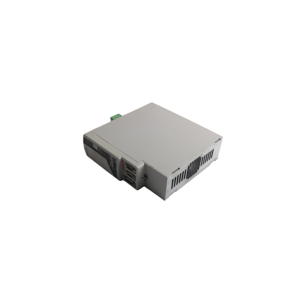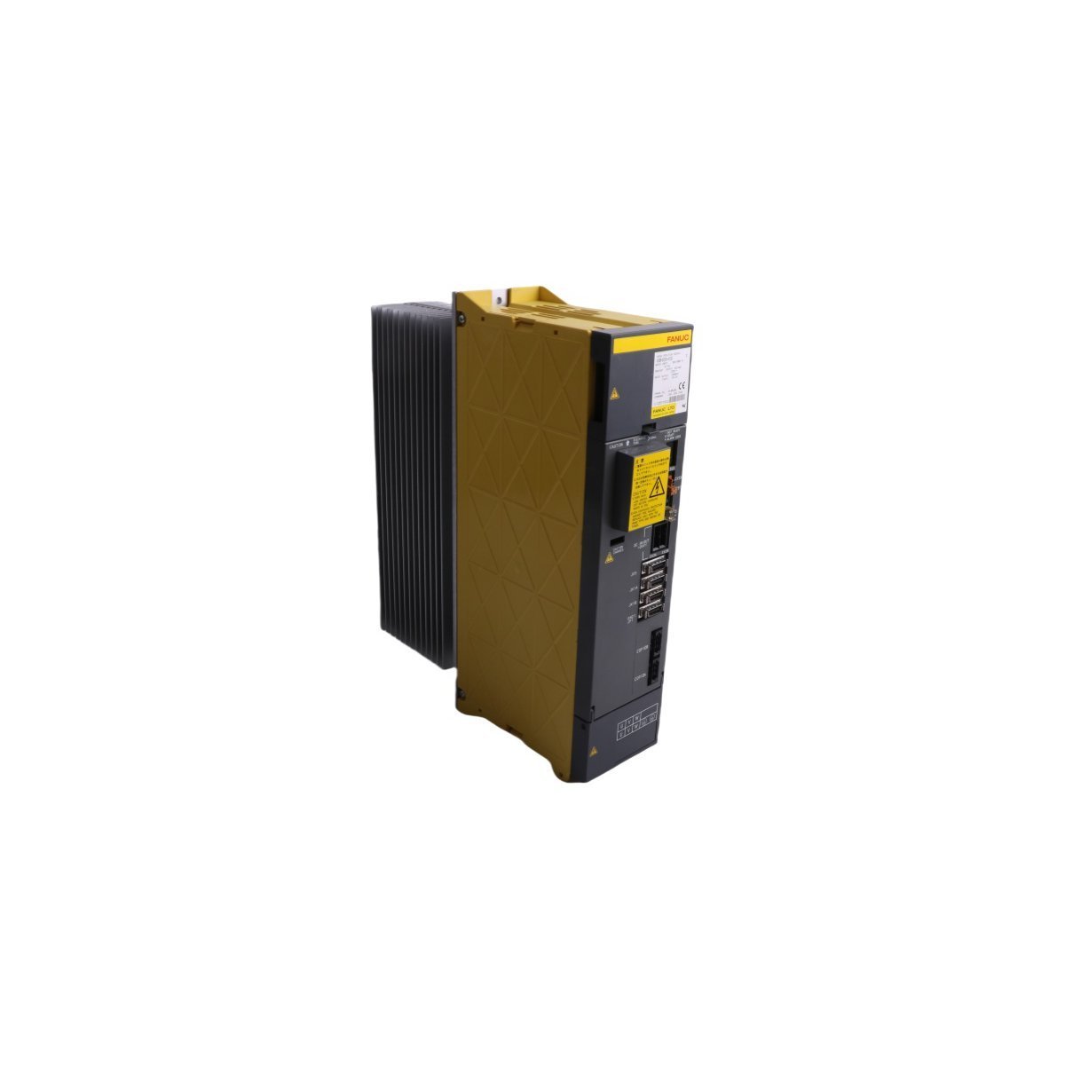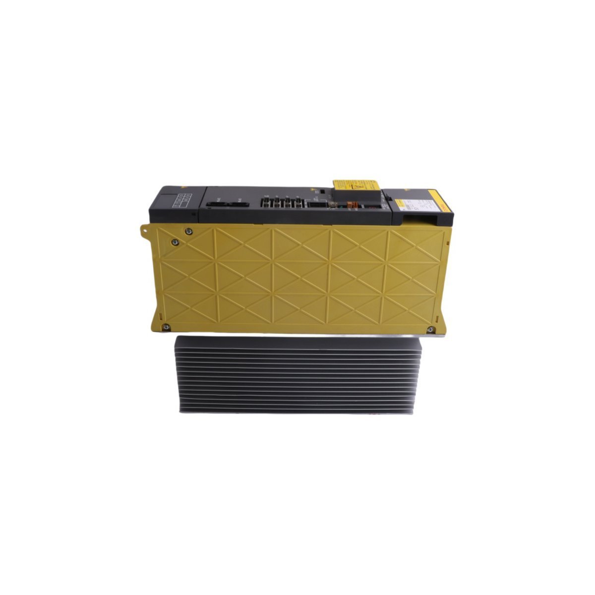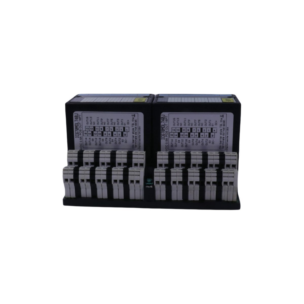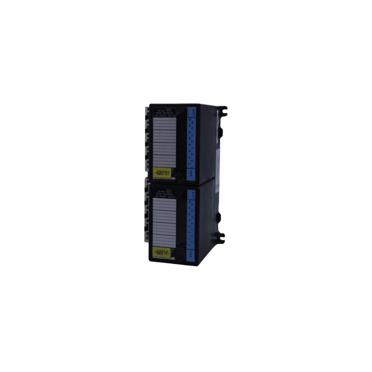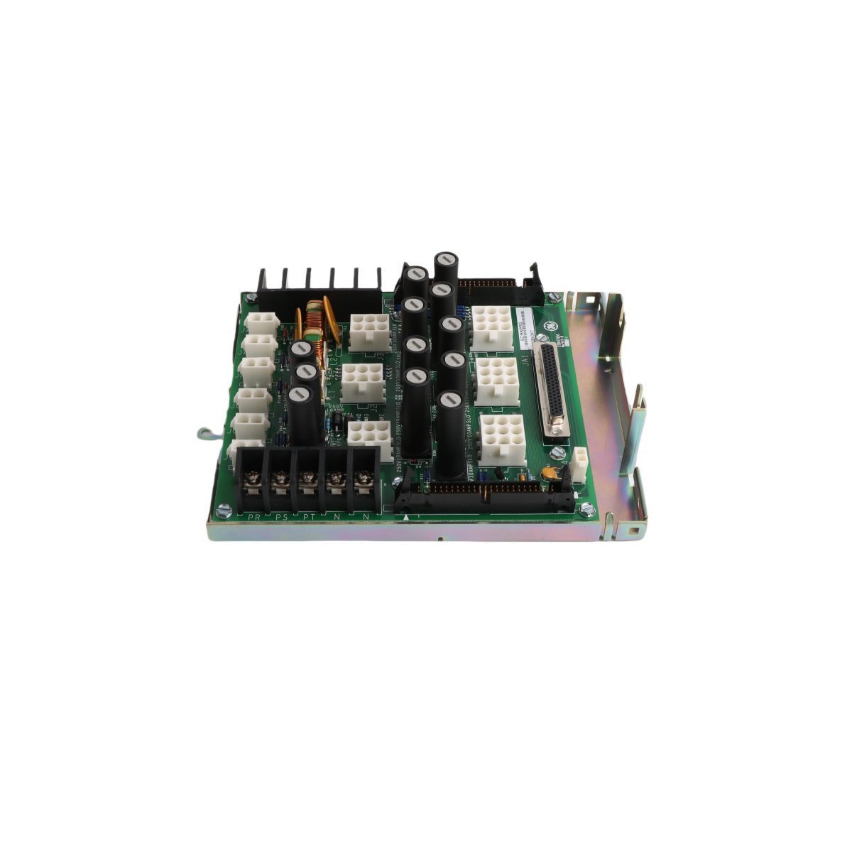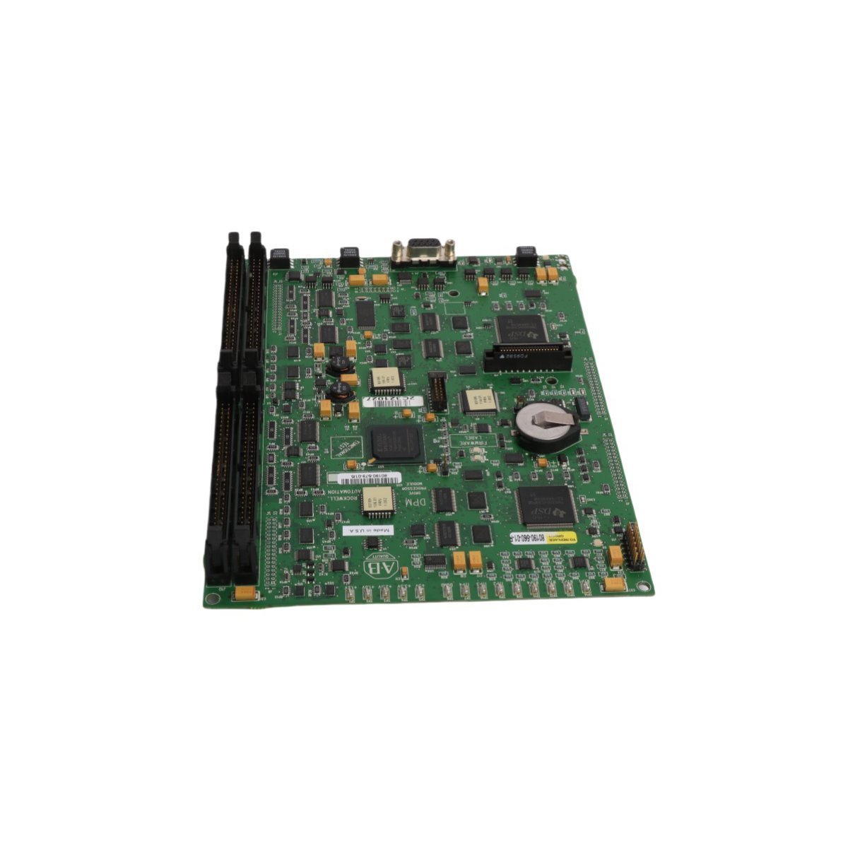
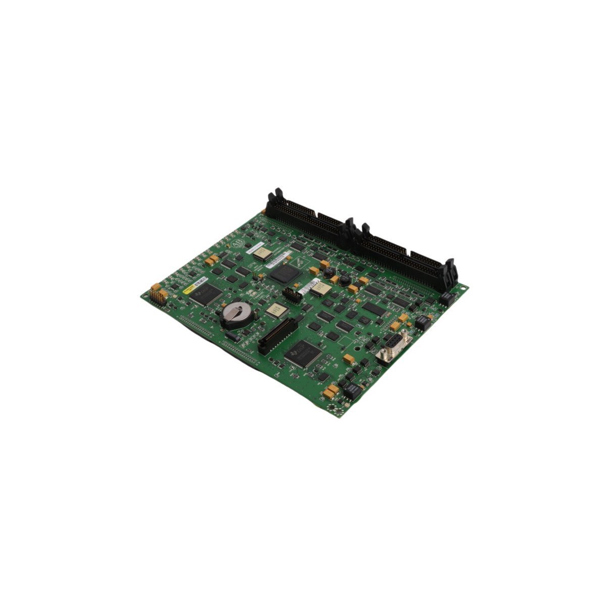

The Allen Bradley 80190-560-01-R, also cataloged as the 80190-560-01-R PC Board, operates as a dedicated hardware component for industrial communication and signal routing within PLC networks.
Hardware Specifications
Parameter
Specification
Model
80190-560-01-R
Brand
Allen Bradley
Origin
USA
Weight
0.4 kg
Dimensions
19.1 x 18.8 x 6.5 cm
Operating Temp
Industrial Standard
Power Consumption
System Backplane Dependent
Primary Function
Ethernet Router / Signal Processing
Profinet and EtherNet/IP Deterministic Network Characteristics
The 80190-560-01-R leverages integrated logic to facilitate deterministic data exchange across industrial networks. Specifically, the module supports high-speed packet routing, thereby minimizing latency in Ethernet-based PLC backplane communication. Furthermore, firmware flash compatibility ensures the hardware remains synchronized with contemporary network protocols. In addition to this, I/O density scaling allows for seamless integration into complex, multi-node automation environments without compromising bus velocity. Consequently, the system maintains strict timing compliance even as network traffic demands increase.
Frequently Asked Questions
Q: Does the 80190-560-01-R support live extraction from the PLC backplane?
A: No. Power must be disconnected from the chassis before installing or removing the PC Board to prevent electrical arcing or damage to backplane pin connectors.
Q: How should the module be configured for network routing?
A: Configuration is performed via the primary PLC programming environment, utilizing the integrated Ethernet router interface to map physical addresses to logical network tags.
Field Installation Guidelines
Ensure the control cabinet power is isolated and locked out before installation.
Inspect the PCB edge connectors for any oxidation or mechanical deformation.
Slide the module into the designated PLC chassis slot, ensuring the backplane connector aligns correctly with the receiving socket.
Secure the module using the top and bottom captive screws to ensure proper grounding and mechanical stability on the DIN rail.
Connect shielded Ethernet cabling to the designated ports, ensuring the cable shield is terminated at the cabinet common ground point to minimize EMI interference.
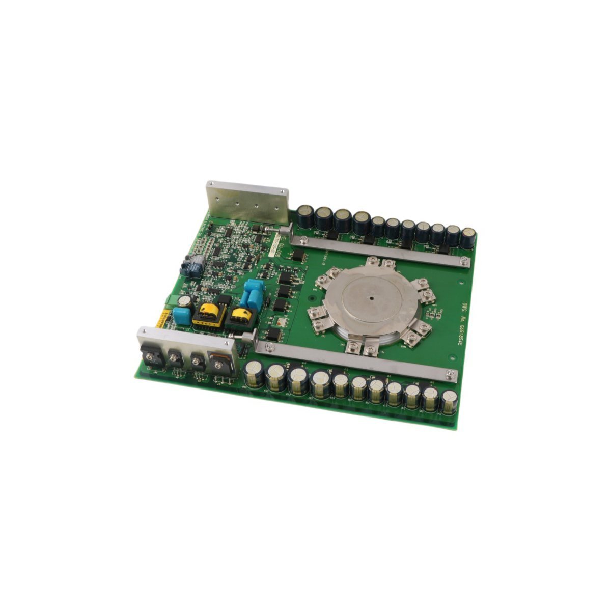
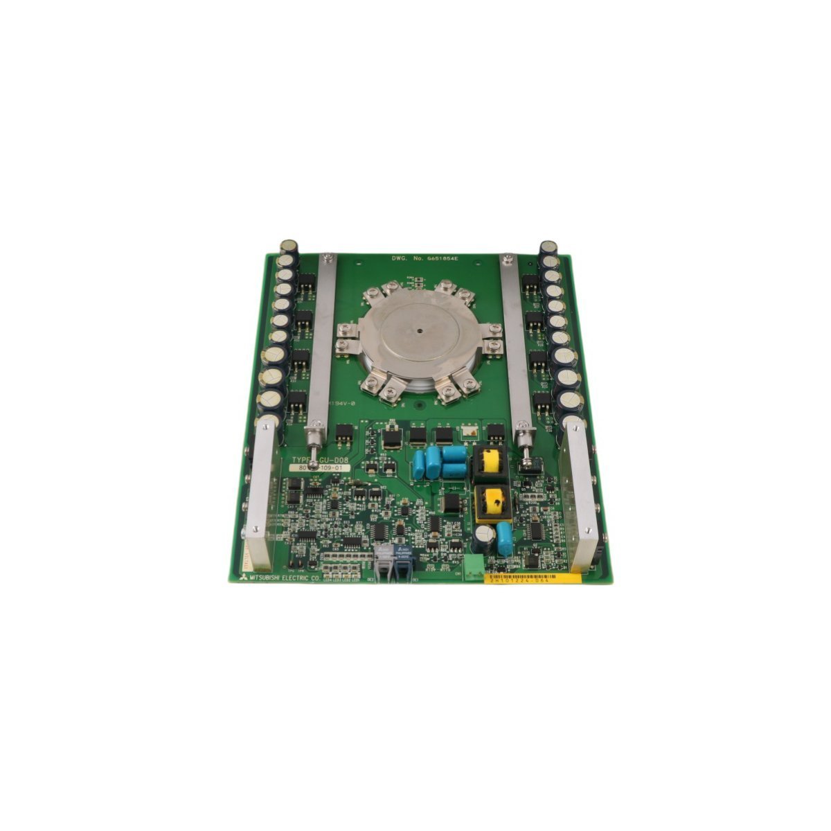
The Allen Bradley 81001-450-52-R Power Block Drive, also cataloged as the 81001-450-52-R Power Block Drive, operates as a dedicated hardware component for power distribution and conversion within PLC platform networks.
Hardware Specifications
Parameter
Specification
Model
81001-450-52-R
Brand
Allen Bradley
Origin
USA
Weight
1.14 kg
Dimensions
25 x 20.7 x 5.5 cm
Operating Temp
Standard Industrial Range
Power Consumption
System Dependent
Module Type
Power Block Drive
PLC Deterministic Network Integration
The Allen Bradley 81001-450-52-R utilizes backplane bus communication protocols designed for integration with PLC control architectures. The module supports deterministic network timing, ensuring low-latency power state feedback and synchronization within complex I/O density configurations. Compatibility with field-programmable firmware allows for flash updates to align with evolving backplane bus communication velocity requirements, maintaining bus traffic integrity and reducing collision potential in high-speed control loops.
Frequently Asked Questions
Q: What are the restrictions regarding the installation of the 81001-450-52-R in a redundant power rack?A: Ensure that the backplane bus address is correctly configured to prevent signal collisions. Redundant power configurations must be verified for voltage matching before closing the primary disconnect.Q: Is this module capable of firmware field-upgrades?A: Yes, the unit supports firmware flash compatibility via the primary control bus. Consult the PLC backplane interface documentation for current revision requirements.
Field Installation Guidelines
Mount the module onto a standard metal DIN-rail. Ensure the rail is bonded to the cabinet chassis ground to minimize EMI.
Maintain a minimum clearance of 50 mm above and below the unit to allow for passive thermal heat dissipation.
All power input cabling must utilize shielded twisted-pair conductors to prevent common-mode noise injection into the PLC backplane.
Verify that the 24 VDC output load does not exceed the continuous current rating specified for the associated PLC power bus segment.
Ensure the connector interface is fully seated until a tactile lock is achieved to prevent intermittent contact resistance.
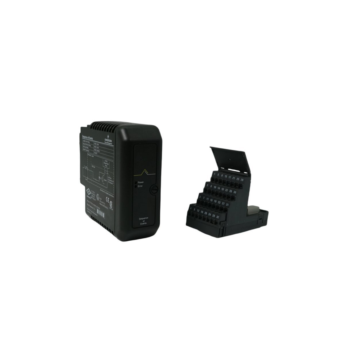
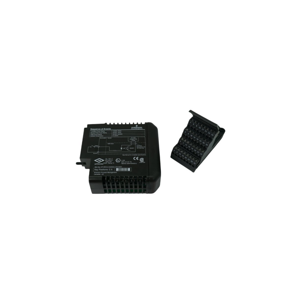
Configured for signal distribution in DeltaV M-series I/O subsystems, the Emerson KJ3222X1-BA1 (KJ3222X1-BA1 Redundant Terminal Block) provides direct physical and electrical execution of field wiring termination for redundant I/O configurations.
Hardware Specifications
Parameter
Specification
Model
KJ3222X1-BA1
Brand
Emerson
Origin
USA
Weight
0.2 kg
Dimensions
4.1 x 12.5 x 10.5 cm
Operating Temp
Standard Industrial Range
Power Consumption
Passive Component
Compatibility
DeltaV M-series I/O
DeltaV DCS Process Control Characteristics
The terminal block facilitates the implementation of 4-20 mA HART loop protocol architectures by providing physical connection points for redundant I/O card pairs. It maintains channel-to-channel isolation through optimized PCB routing, preventing cross-talk between high-density loops. The mechanical design ensures cold junction compensation (CJC) stability when integrated with thermocouple input channels. By utilizing the redundant terminal architecture, the system maintains continuous signal integrity for critical control loops, allowing for maintenance operations on one I/O module without disrupting the current loop of the secondary redundant partner.
Frequently Asked Questions
Q: Does the KJ3222X1-BA1 support active electronic components?A: No, this is a passive terminal block. It serves as an interface between field wiring and the DeltaV I/O carrier, routing signals to the redundant I/O module pair.Q: Can this terminal block be used for non-redundant I/O configurations?A: While designed for redundancy, the terminal block provides the physical interface required for specific DeltaV M-series modules. Compatibility must be verified against the specific I/O module part number (VE4033S2B1) to ensure pin mapping alignment.
Field Installation Guidelines
Prior to wiring, verify that the I/O carrier power is disconnected to prevent accidental contact with energized field circuits.
During installation, align the terminal block with the mating connectors on the DeltaV I/O carrier, ensuring the guide pins are fully seated before tightening the retention screws.
When connecting field devices, ensure that shielded, twisted-pair cabling is utilized for all 4-20 mA loops to mitigate electromagnetic interference.
Upon securing the wiring, verify the continuity of the redundant paths using a digital multimeter at the terminal points before initiating loop commissioning.
Maintain appropriate physical separation between the terminal block wiring and any high-voltage AC lines to prevent induced noise on the analog signal loops.
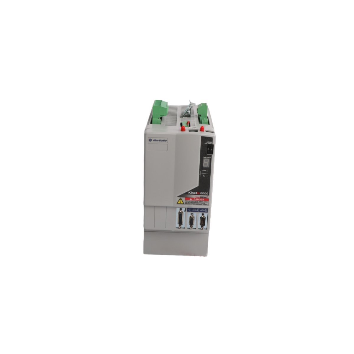
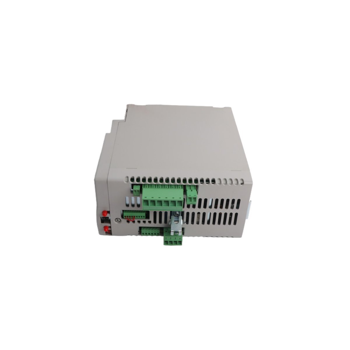
Configured for high-performance motion control in Kinetix 6000 multi-axis drive systems, the Allen-Bradley 2094-BM03-S (2094-BM03-S Axis Module) provides direct physical and electrical execution for rotary and linear motor regulation.
Hardware Specifications
Parameter
Specification
Model
2094-BM03-S
Brand
Allen-Bradley
Origin
USA
Weight
0.9 kg
Dimensions
3.5 cm x 13 cm x 14.5 cm
Operating Temp
Standard industrial range
Power Consumption
200 W continuous (dissipation)
Continuous Current
21.2 A
Peak Current
53.0 A
Power Output
13.5 kW
Industrial Control System Connectivity
The 2094-BM03-S integrates into industrial control platforms by utilizing high-speed backplane bus communication protocols for real-time motion synchronization. This modular architecture facilitates I/O density scaling within the drive cabinet, which allows the system to manage complex motion feedback loops efficiently. Furthermore, the module supports firmware flash compatibility, enabling engineers to update internal logic for specific application requirements. Consequently, the drive ensures deterministic response times during acceleration, deceleration, and power threshold excursions.
Frequently Asked Questions (FAQ)
Q: Does this axis module support hot-swapping within the Kinetix 6000 power rail?A: No, you must isolate the drive system from all primary power sources and verify that the DC bus is fully discharged before you remove or insert the module to prevent damage to the backplane interface.Q: How does the module handle feedback signal integration?A: The 2094-BM03-S interfaces directly with motor feedback cables, processing auxiliary encoder signals to maintain precise position tracking and velocity regulation during operation.
Field Installation Guidelines
To begin with, ensure all power to the drive assembly is strictly isolated and that the DC bus voltage has dissipated to a safe level;Â consequently, this prevents accidental electrical discharge during handling.
Subsequently, mount the module onto the dedicated Kinetix power rail;Â furthermore, ensure that the mechanical locking tabs engage securely to provide the necessary ground contact and structural stability.
In addition, connect the motor feedback cables and interface wires to the front-panel terminals, ensuring that all shields are terminated at the designated ground lugs to suppress electromagnetic interference;Â meanwhile, verify the cable bend radius to prevent permanent fiber or conductor damage.
Following physical mounting, perform a thorough check of all electrical connections before applying system power;Â by doing so, you minimize the risk of short-circuits on the backplane.
Finally, confirm that the motion controller configuration matches the physical addressing and firmware version of the 2094-BM03-S to enable stable data exchange and command execution on the bus.
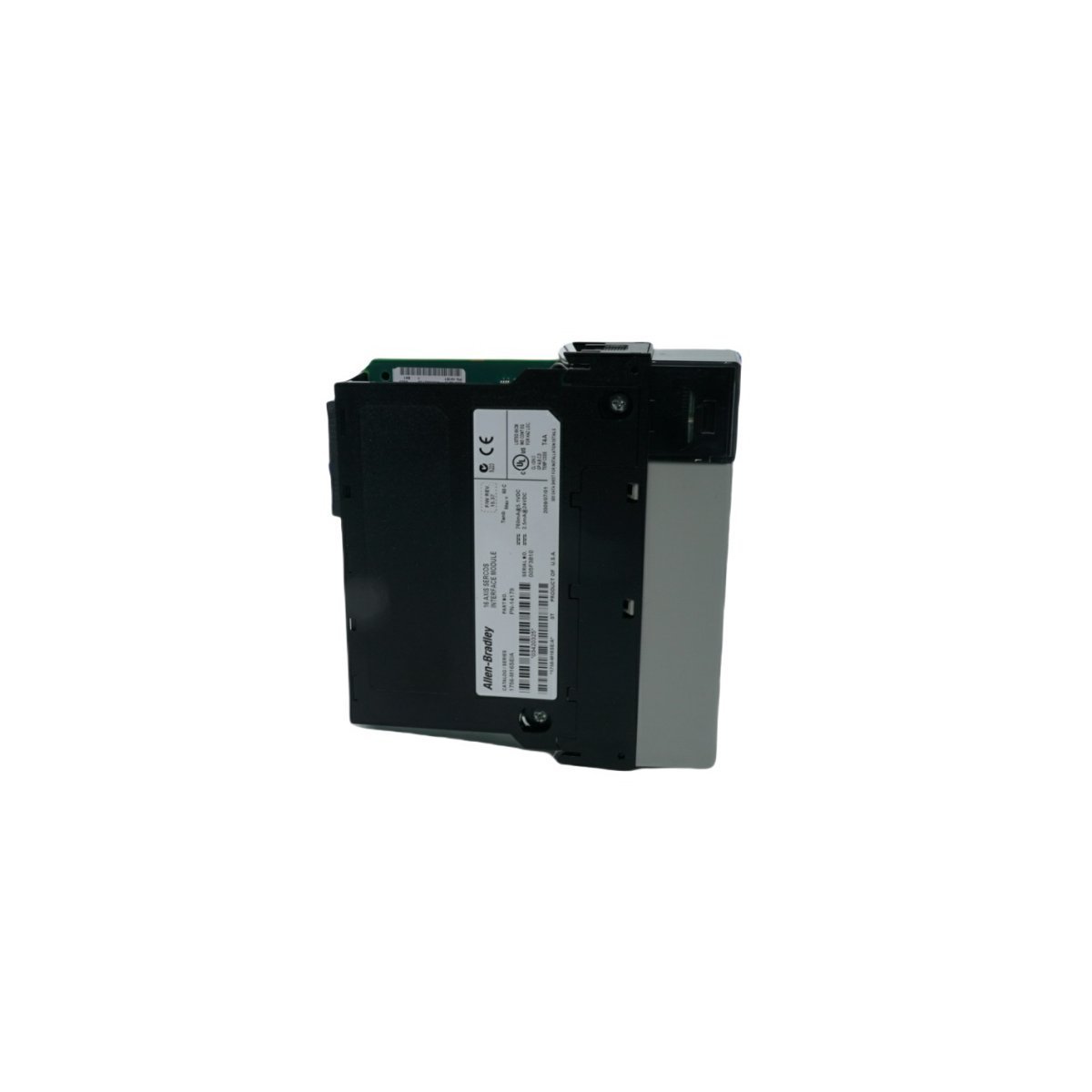
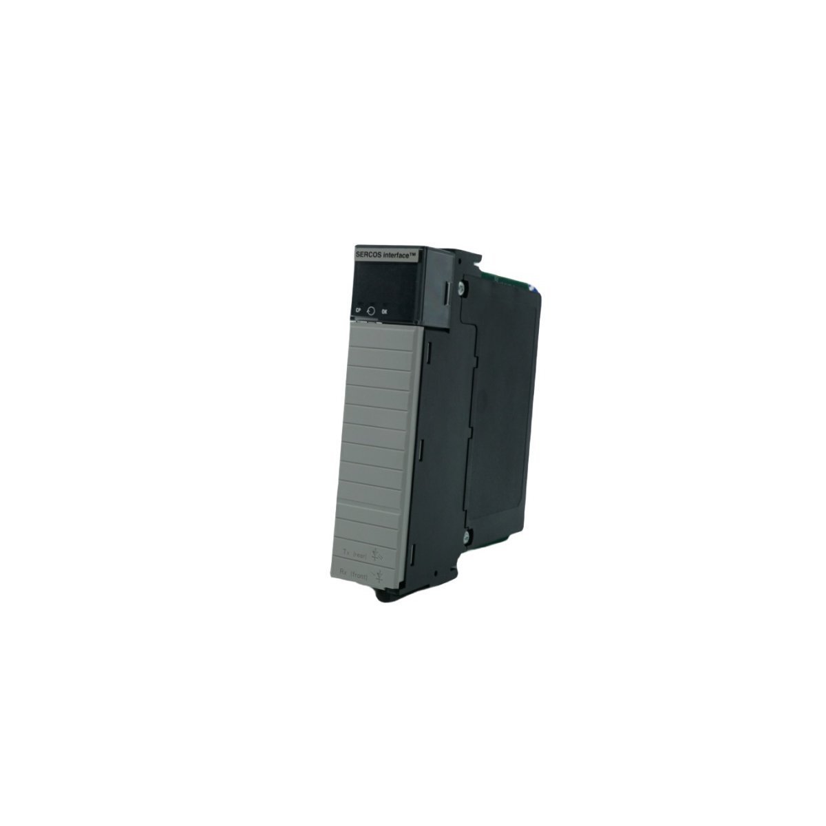
Configured for high-speed motion synchronization in ControlLogix systems, the Allen-Bradley 1756-M16SE (1756-M16SE SERCOS interface Module) provides direct physical and electrical execution for multi-axis servo drive command distribution.
Hardware Specifications
Parameter
Specification
Model
1756-M16SE
Brand
Allen-Bradley
Origin
USA
Weight
0.22 kg
Dimensions
3.5 cm x 14 cm x 14.5 cm
Operating Temp
Standard industrial range
Power Consumption
Backplane dependent
Data Rate
4 Mbps or 8 Mbps
Axis Capacity
16 axes per module
PLC Control and Communication Characteristics
The 1756-M16SE utilizes high-speed backplane bus communication velocity to manage deterministic data exchange between the ControlLogix CPU and remote servo drive nodes. By leveraging digital fiber-optic SERCOS interfaces, the module achieves I/O density scaling that minimizes signal propagation latency across 16 managed axes. Furthermore, the module supports firmware flash compatibility, which allows for site-specific motion algorithm updates without physical hardware replacement. This deterministic network structure ensures that position, velocity, and torque command loops maintain sub-millisecond synchronization even in high-density drive configurations.
Frequently Asked Questions (FAQ)
Q: What are the primary limitations when configuring the SERCOS ring topology for the 1756-M16SE?A: The ring topology is limited by the physical length of the fiber-optic cabling and the total number of connected nodes; you must ensure the total loop latency does not exceed the configured cycle time (0.5 ms or 1.0 ms) to maintain deterministic operation.Q: Is the 1756-M16SE module capable of hot-swapping within an active ControlLogix chassis?A: The module supports standard ControlLogix hot-swap procedures; however, removing the module will immediately drop the SERCOS ring communication, causing all connected servo drives to transition to their programmed fault state.
Field Installation Guidelines
To begin with, confirm the ControlLogix chassis backplane is powered down; subsequently, insert the 1756-M16SE into a designated slot and secure it using the integrated module locking screws to ensure proper backplane contact.
In addition, route the SERCOS fiber-optic cables following the ring or linear topology requirements;Â meanwhile, maintain the minimum bend radius of the fiber to prevent micro-fractures that induce signal loss.
Furthermore, ensure all fiber-optic connectors are clean and free of contaminants before insertion into the module transceivers;Â consequently, this prevents optical attenuation that could lead to intermittent link failures.
Finally, configure the module addressing and axis scaling within the control software;Â by doing so, you ensure the controller can successfully establish the SERCOS communication cycle with the downstream Kinetix drives.
The GE IS200TDBSH2A is a Mark VI discrete simplex terminal board designed for turbine control systems. It provides 96 robust connection points for efficient signal management.
The Allen-Bradley 80190-600-01-R is an industrial optical interface base circuit board. Brand New, Original Stock, Global Shipping available for immediate deployment.
The Allen-Bradley 1791DS-IB8XOB8 is a 16-point Guard I/O safety combination block for DeviceNet networks. Featuring 8 safety inputs, 8 solid-state sourcing safety outputs, and 4 test outputs, this compact DIN-rail module delivers SIL 3 / Category 4 protection with onboard cross-fault diagnostics for machine safety applications.
The Allen-Bradley 1492-IFM20F-F120A-2 is a 20-point fusible termination module featuring 120V AC/DC blown-fuse indicators and group isolation. It provides robust circuit protection and simplified field wiring for industrial PLC systems.
The GE Fanuc IC670CHS002 is a high-performance terminal block for Field Control systems. It features isolated common groups (A, B, and E) for flexible power distribution and a modular design that allows for I/O module replacement without disconnecting field wiring.
The Yokogawa SNT501-13 is a premium Optical ESB Bus Repeater Module designed for long-distance DCS and SIS communication. It supports high-speed 128 Mbps data transfer over fiber optics up to 5 km, providing the EMI immunity and redundancy required for mission-critical industrial automation safety.
The ICS Triplex T8311 is a high-reliability Expander Interface for the Trusted TMR system. It enables secure I/O bus expansion across multiple chassis, featuring a durable aluminum housing, high-speed data synchronization, and full fault-tolerant compatibility for SIL 3 safety applications.
The GE Multilin UR8GH is a high-precision Voltage Transformer (VT) module designed for the Universal Relay (UR) series. This 0.36kg digital I/O module provides accurate secondary signal processing for CT/VT devices, enabling real-time monitoring, fault detection, and robust protection in utility substations and complex industrial power systems.
We are committed to protecting your privacy. The information collected here is strictly used to provide the requested quotes, technical support, and relevant industrial automation solutions.