Sale!
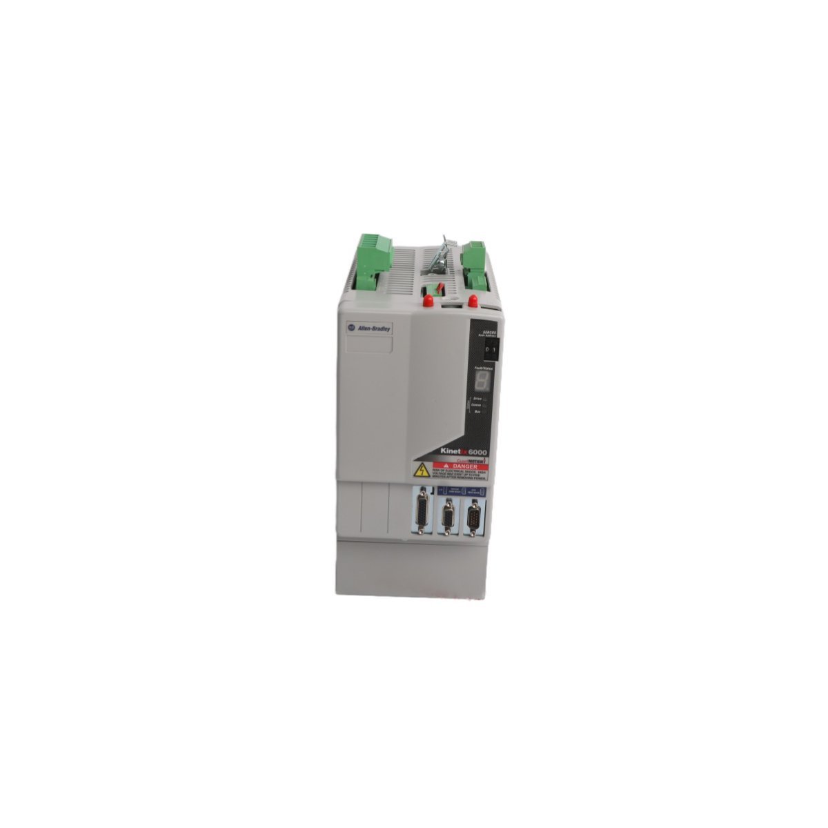
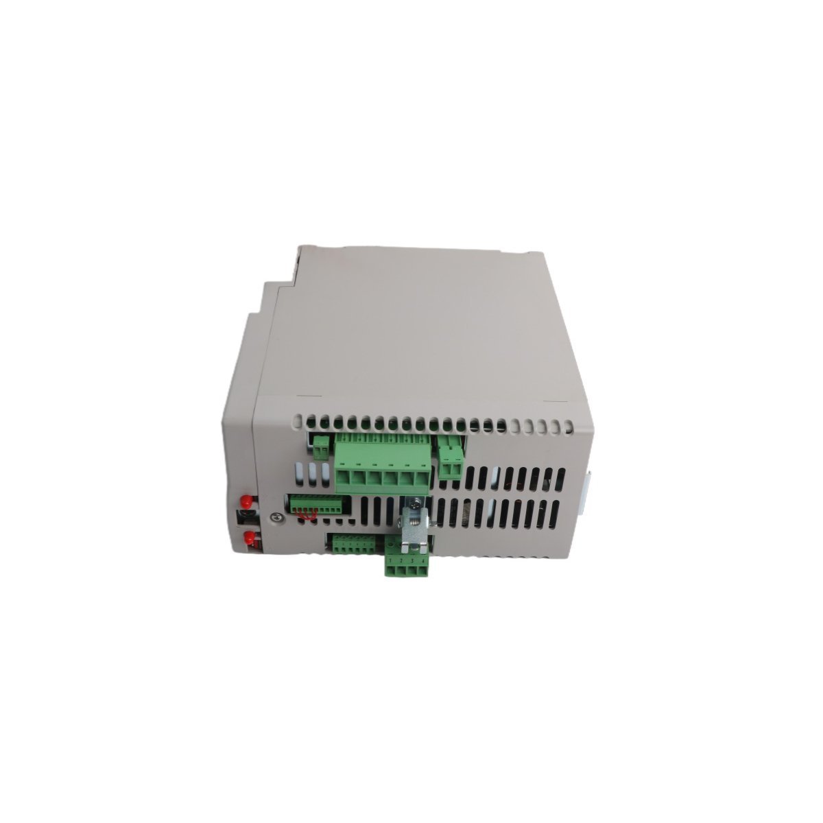
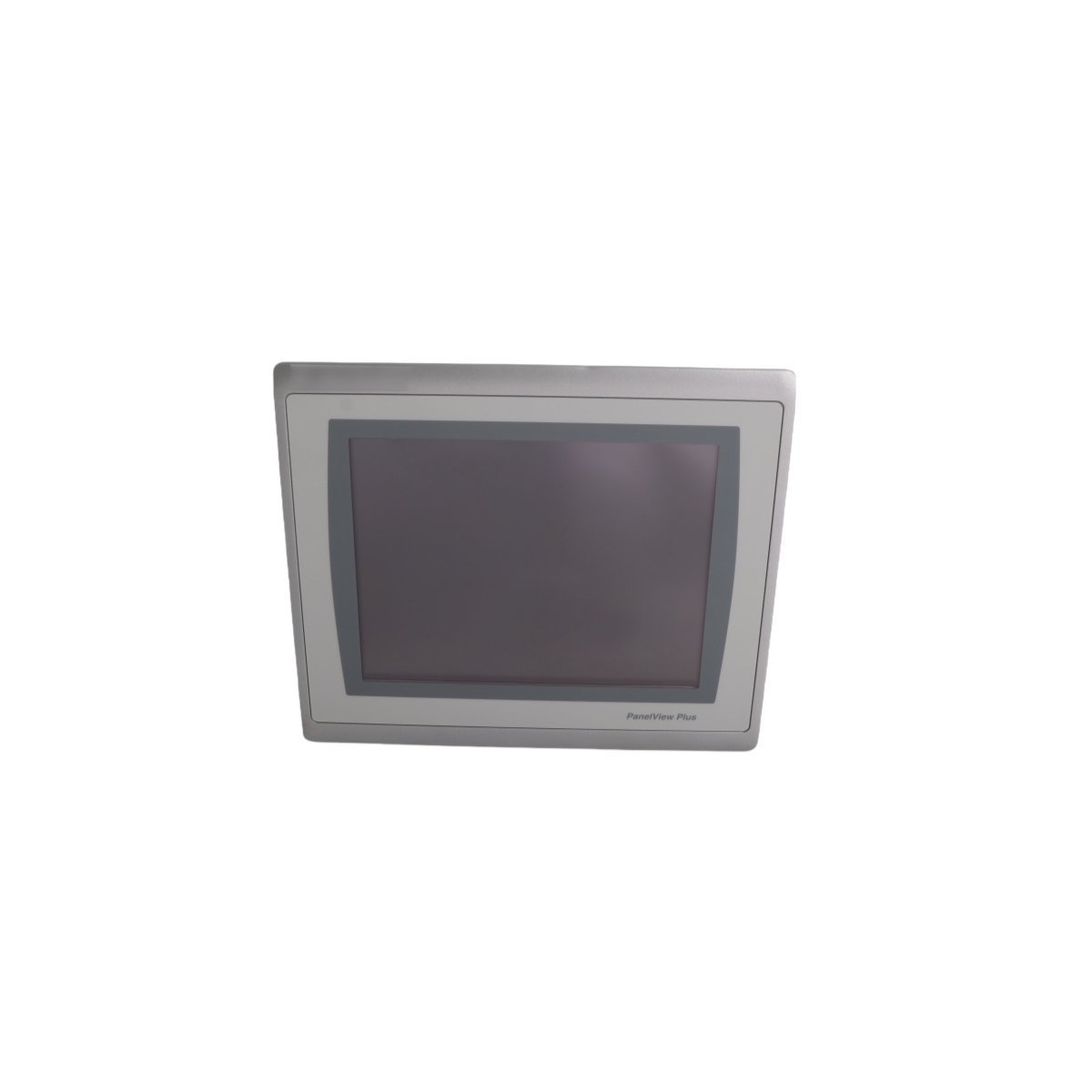
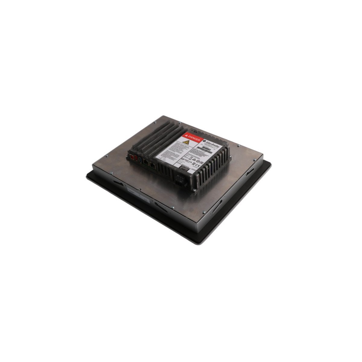
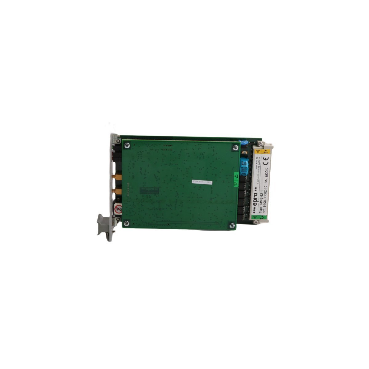
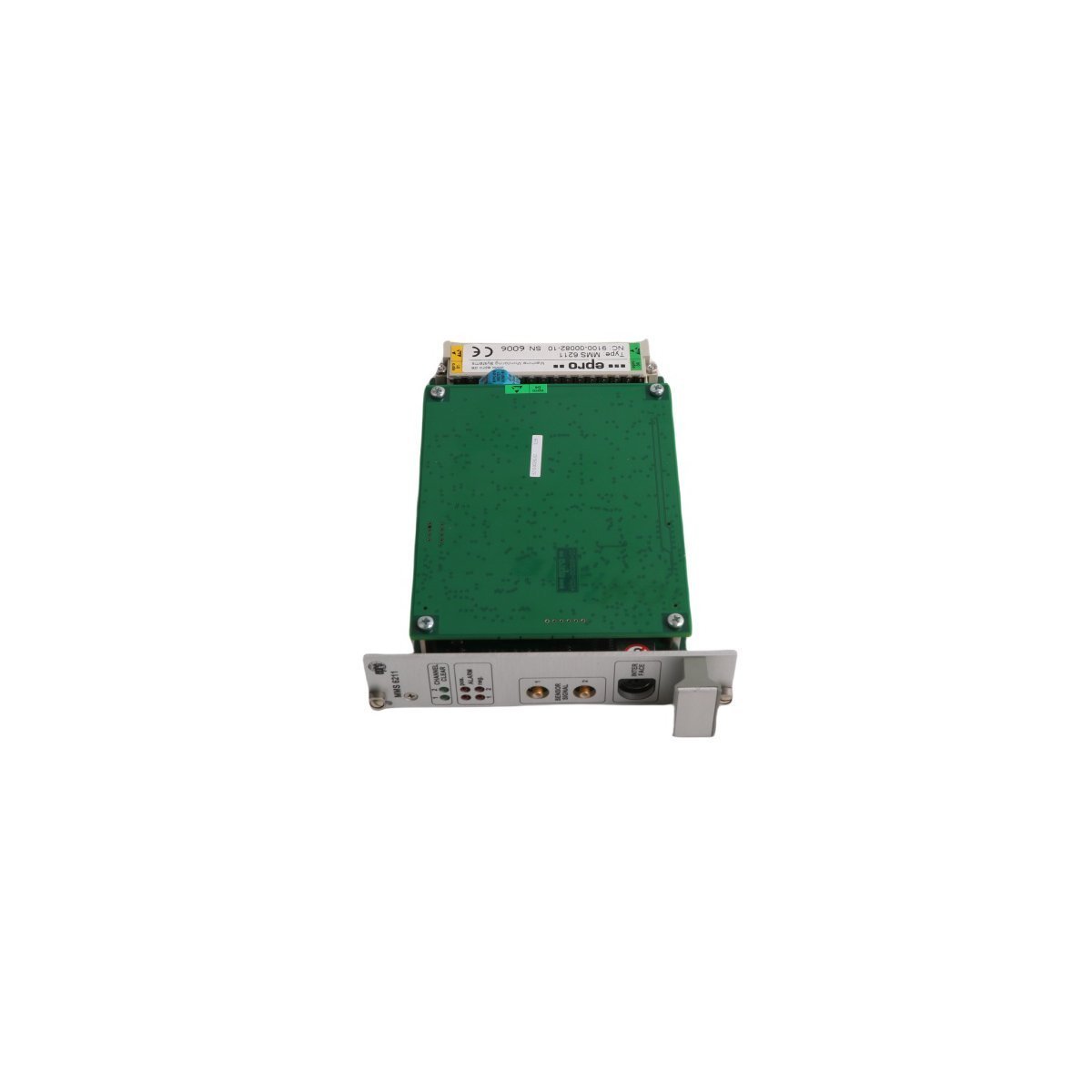
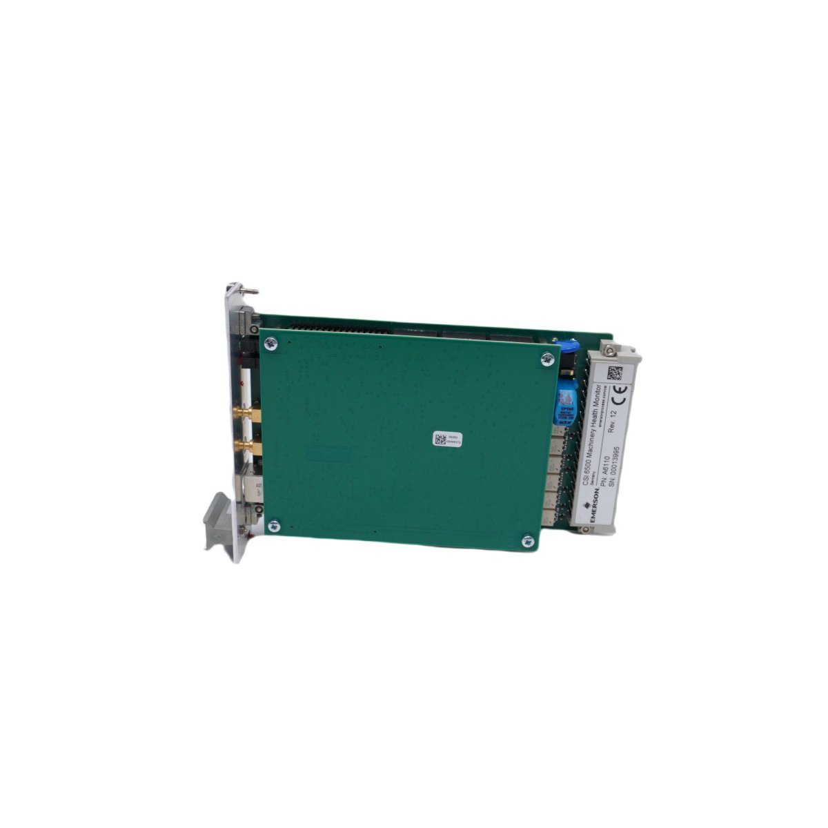
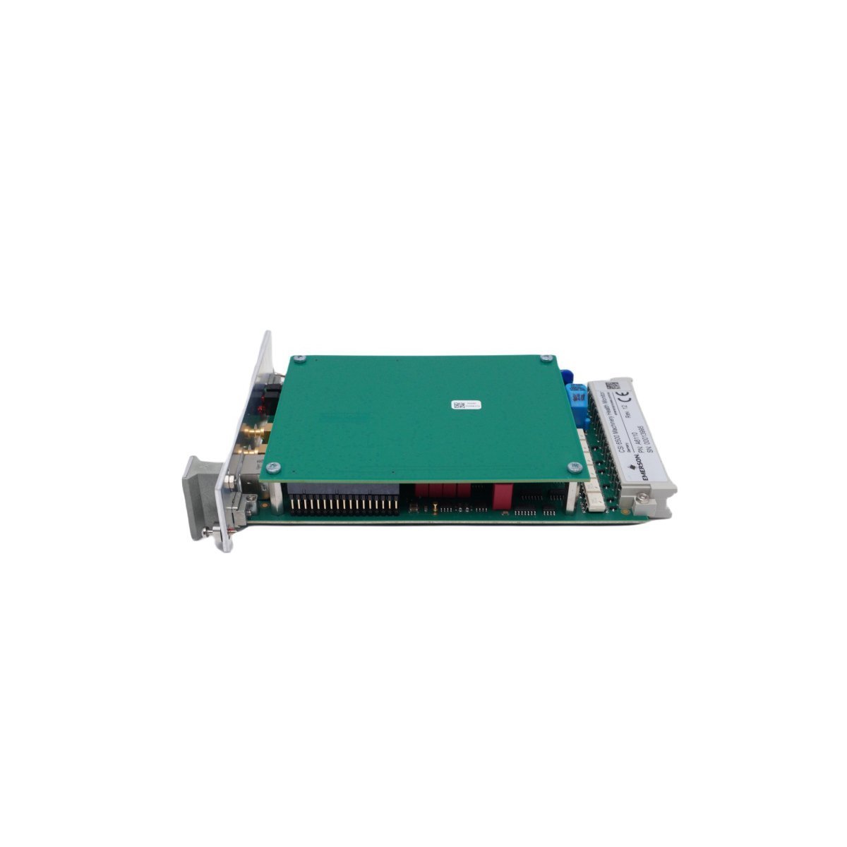
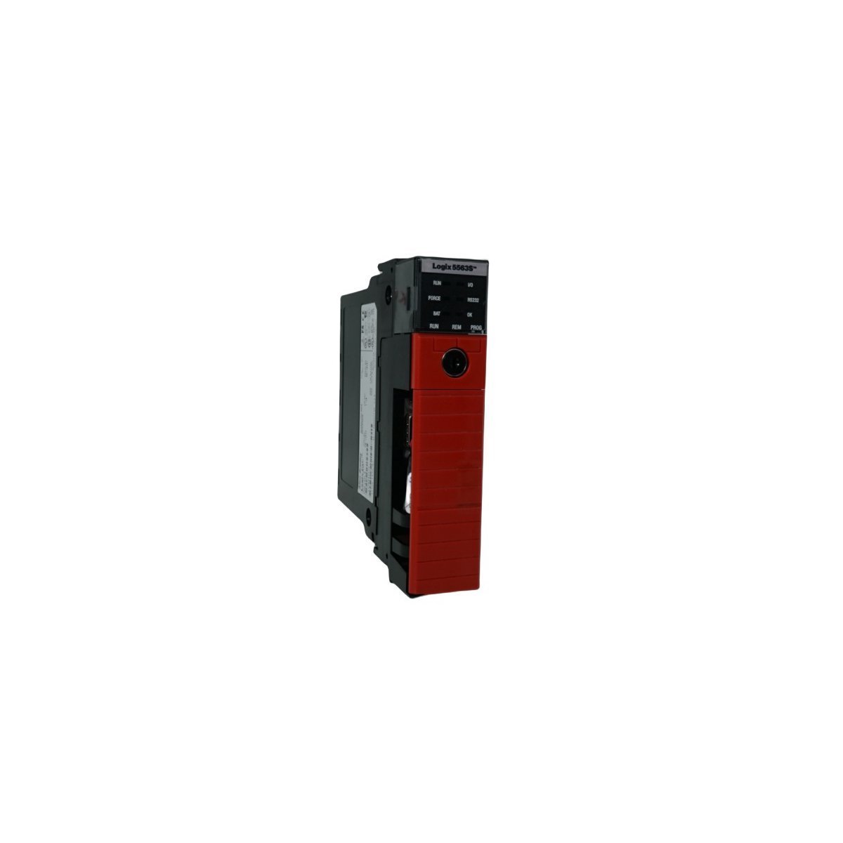
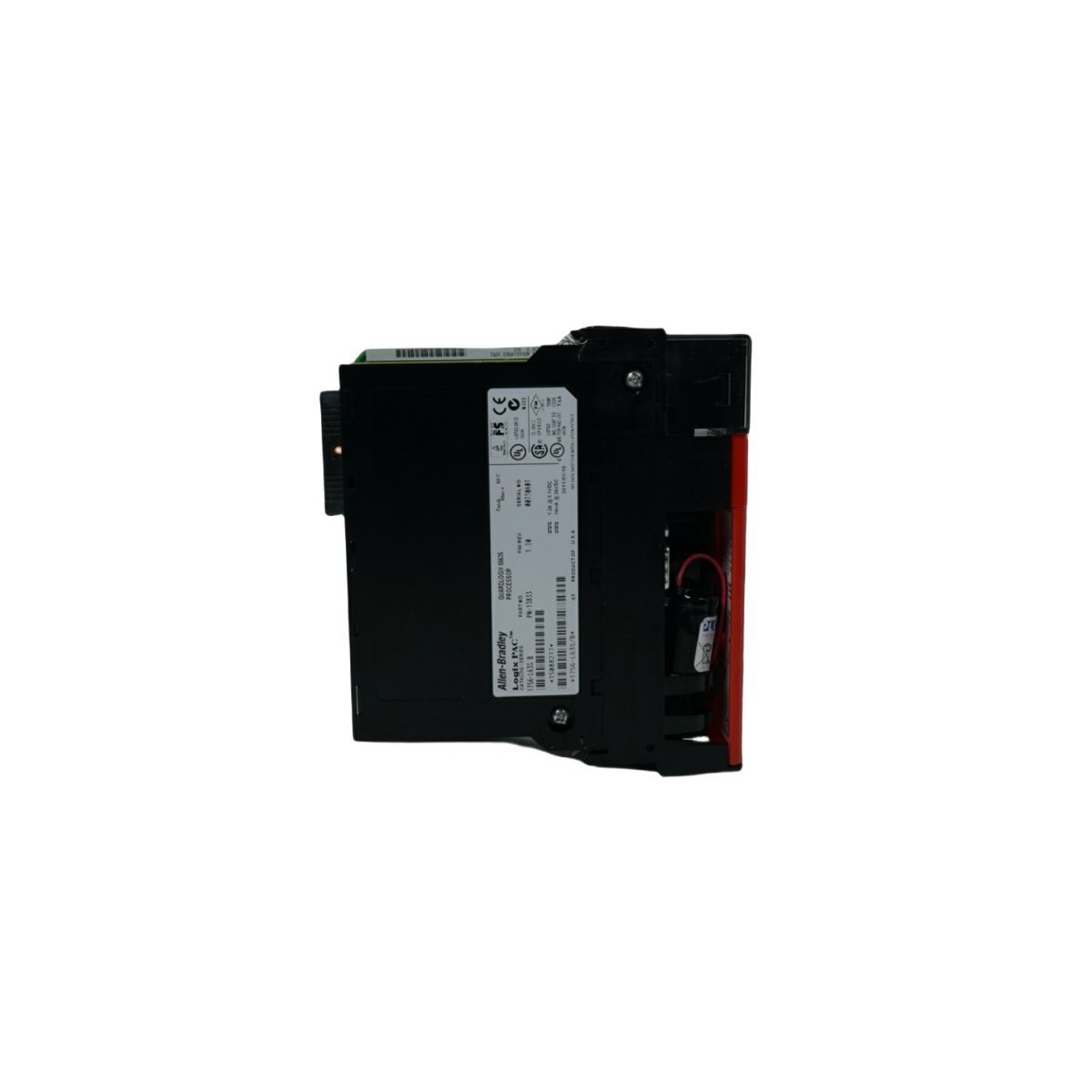
Allen-Bradley 2094-BC01-M01-S Integrated Axis Module
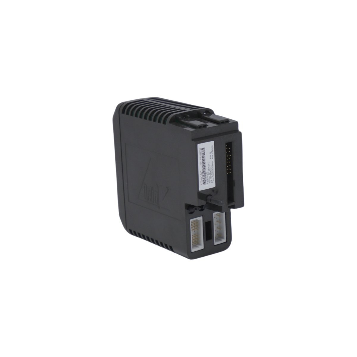
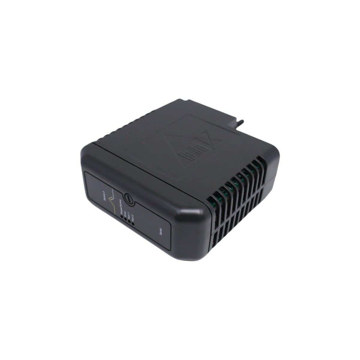
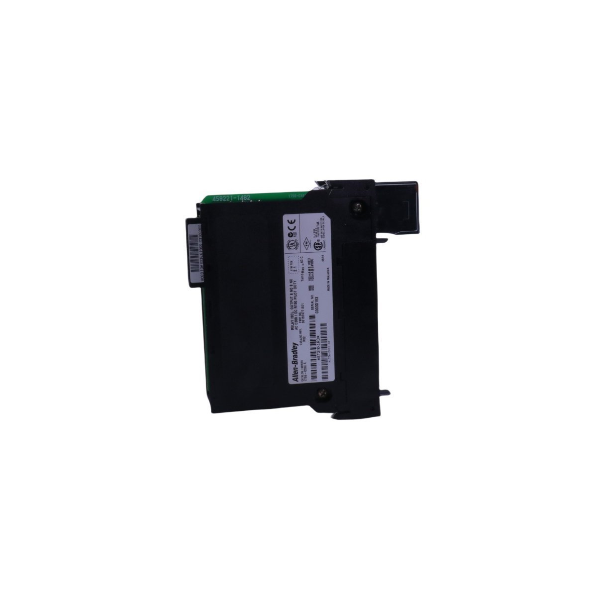
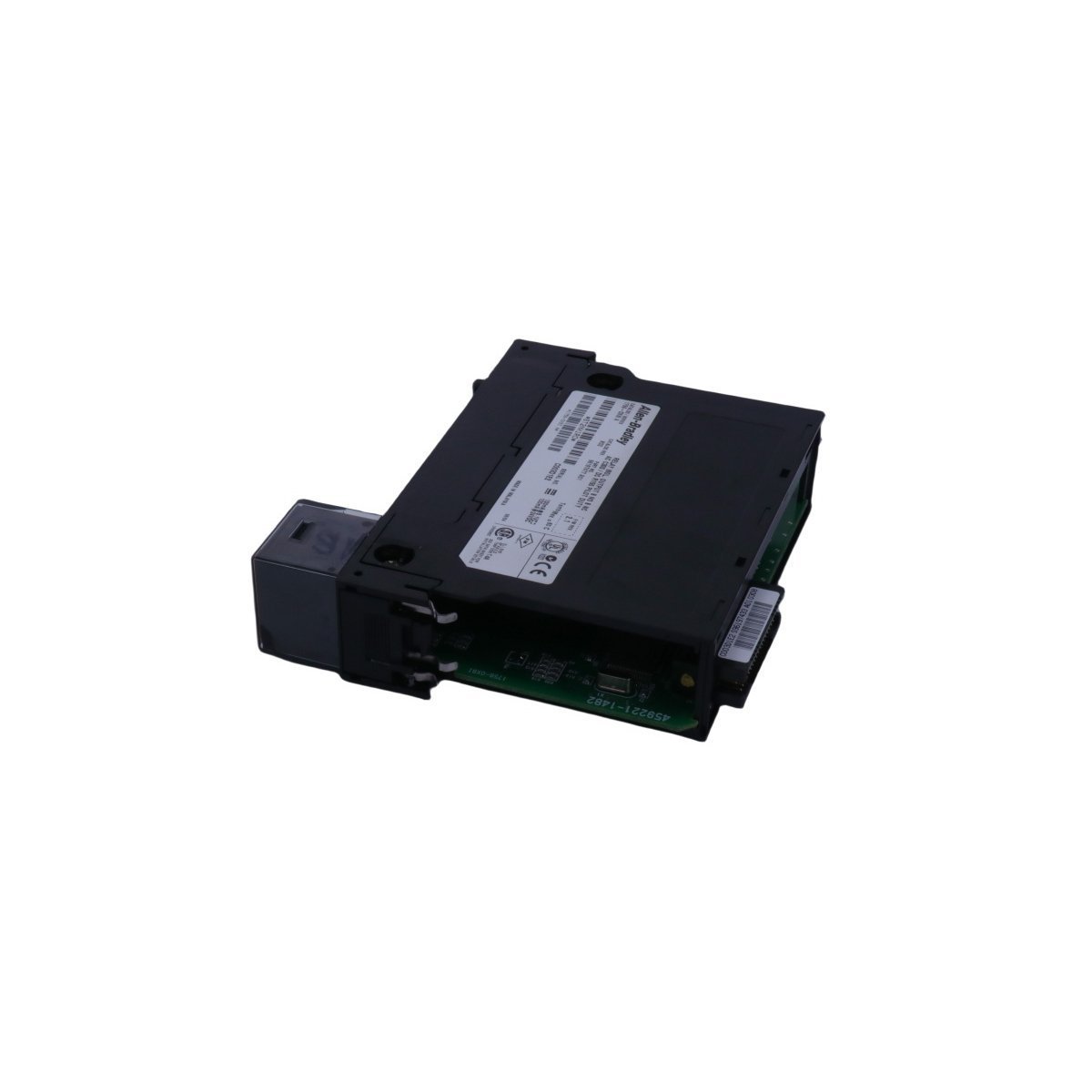
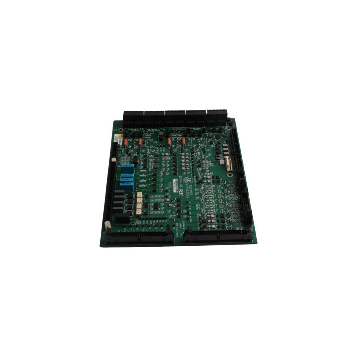
The Allen-Bradley 2094-BC01-M01-S, also cataloged as the 2094-BC01-M01-S Integrated Axis Module, operates as a dedicated hardware component for high-speed motion control and power regulation within Kinetix 6000 multi-axis drive platforms.
Hardware Specifications
| Parameter | Specification |
| Model | 2094-BC01-M01-S |
| Brand | Allen-Bradley |
| Origin | USA |
| Weight | 0.9 kg |
| Dimensions | 3.5 cm x 13 cm x 14.5 cm |
| Operating Temp | Standard industrial range |
| Power Consumption | 3.9 kW (Total) |
| Inverter Current | 9 A |
| Input Voltage | 360-480 V AC |
PLC and Drive Control Characteristics
The 2094-BC01-M01-S incorporates backplane bus communication velocity protocols, enabling deterministic synchronization between the converter and inverter stages. The architecture facilitates I/O density scaling within the drive cabinet, allowing for coordinated power distribution across multiple integrated axes. Furthermore, the module supports firmware flash compatibility, which ensures that internal logic remains aligned with system-wide motion control requirements. This design enables precise control over power threshold excursions and maintains stable torque output during transient loading conditions.Frequently Asked Questions (FAQ)
Q: What are the primary communication requirements for the SERCOS interface on this module?A: The SERCOS interface requires fiber optic media configured in either linear or ring topologies; ensure that the fiber ends are polished and properly seated in the transceivers to maintain signal integrity and avoid communication latency.Q: Can the Safe Torque Off (STO) function be bypassed if not required by the application?A: The STO circuit must remain closed via the designated safety input terminals to enable drive operation; if the safety function is not utilized, you must jumper these inputs according to the installation manual to permit the pulse-width modulation (PWM) output to the motor.Field Installation Guidelines
- To begin with, ensure all primary power is disconnected and the DC bus capacitors have reached a discharge state before you mount the module onto the power rail; subsequently, verify that the rear-facing power connectors align correctly to prevent pin deformation.
- Furthermore, terminate all motor feedback cables using the appropriate shielded connectors; in addition, ensure the shield drain wire connects to the designated ground lug to minimize electromagnetic interference (EMI).
- When configuring the SERCOS ring, route fiber optic cables with a sufficient bend radius to prevent signal attenuation; meanwhile, label each fiber connection to identify the transmit (Tx) and receive (Rx) paths clearly.
- Finally, verify the input voltage range (360-480 V AC) matches the site supply before you apply power; by doing so, you ensure the internal power conversion stage functions within rated limits.