Sale!
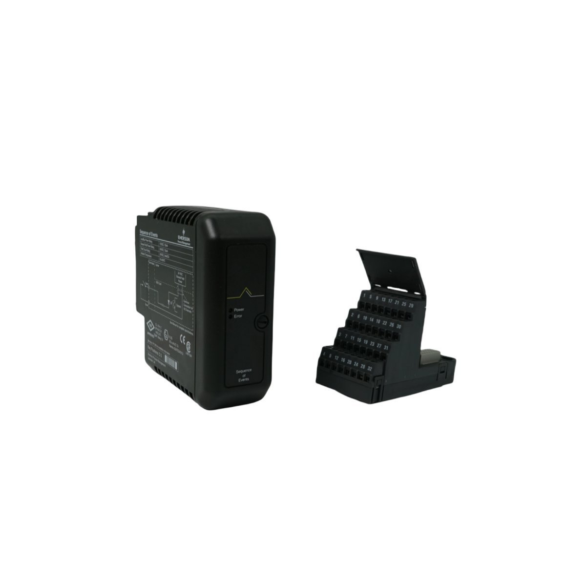
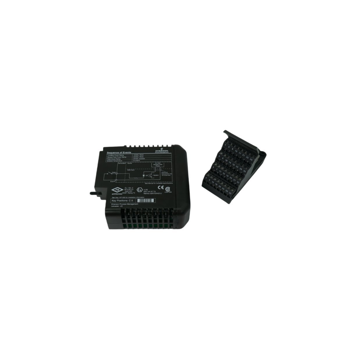
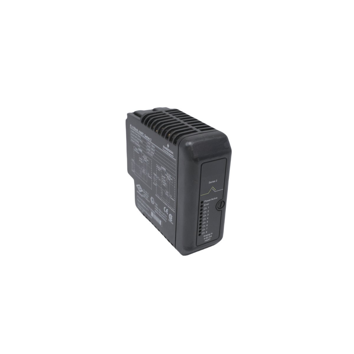
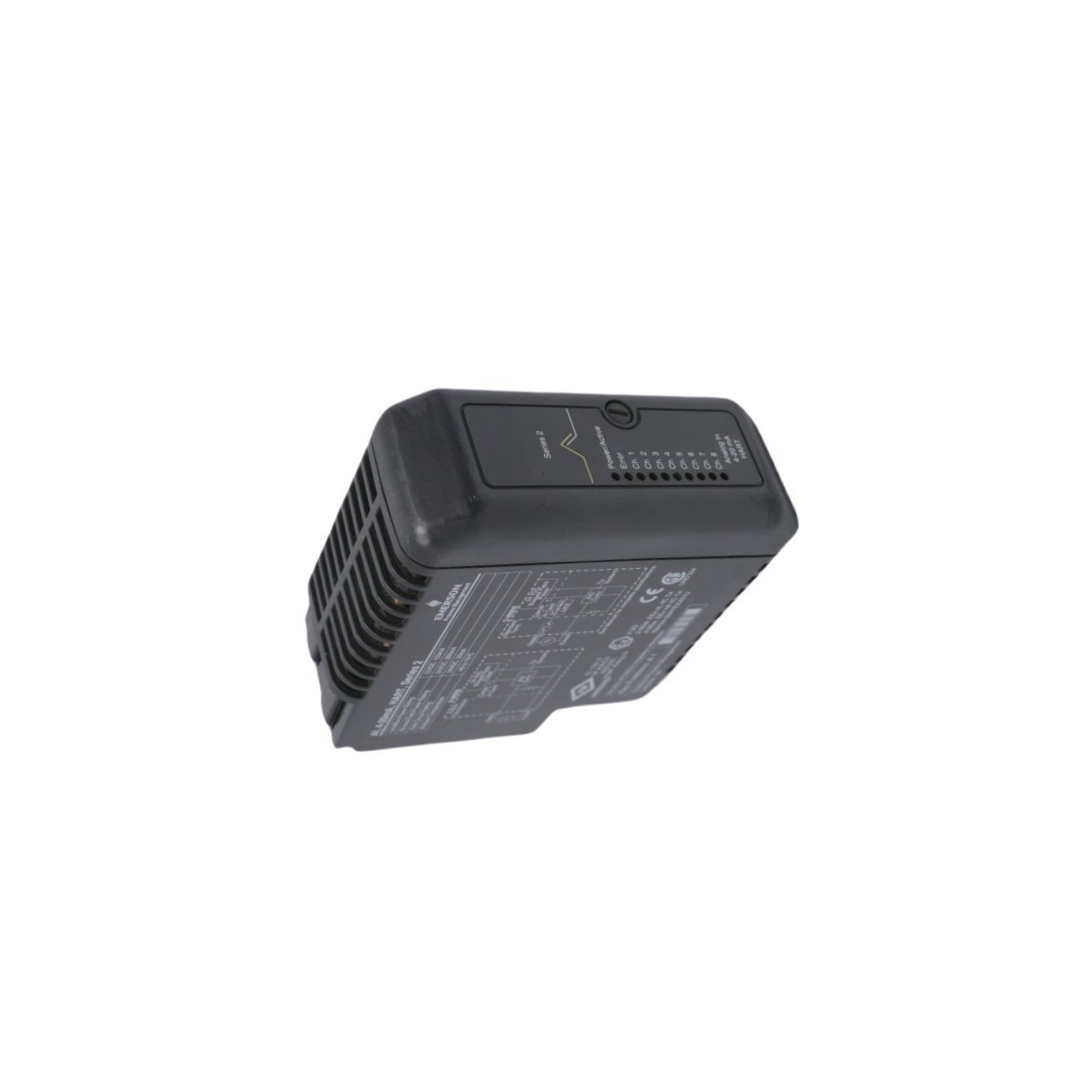
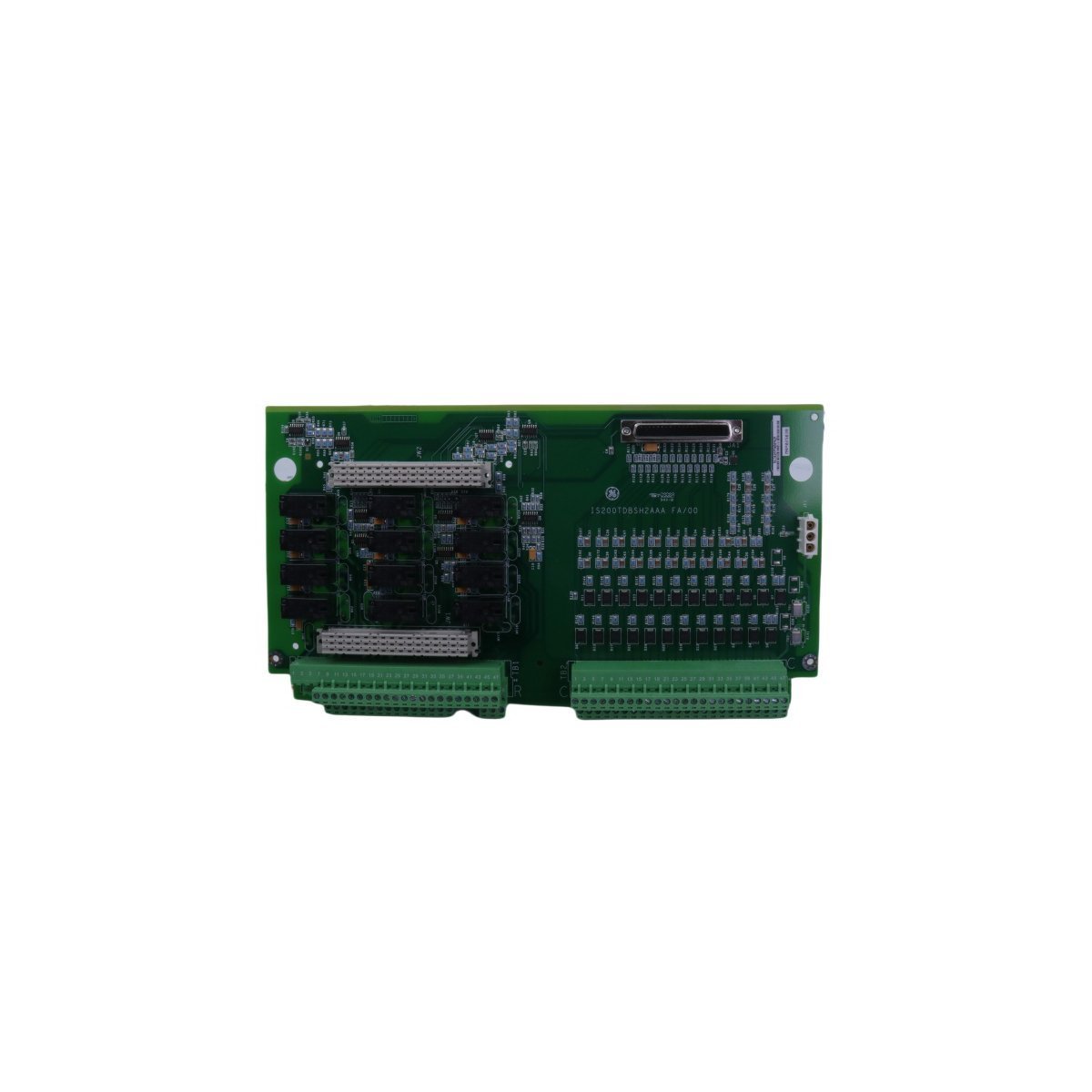
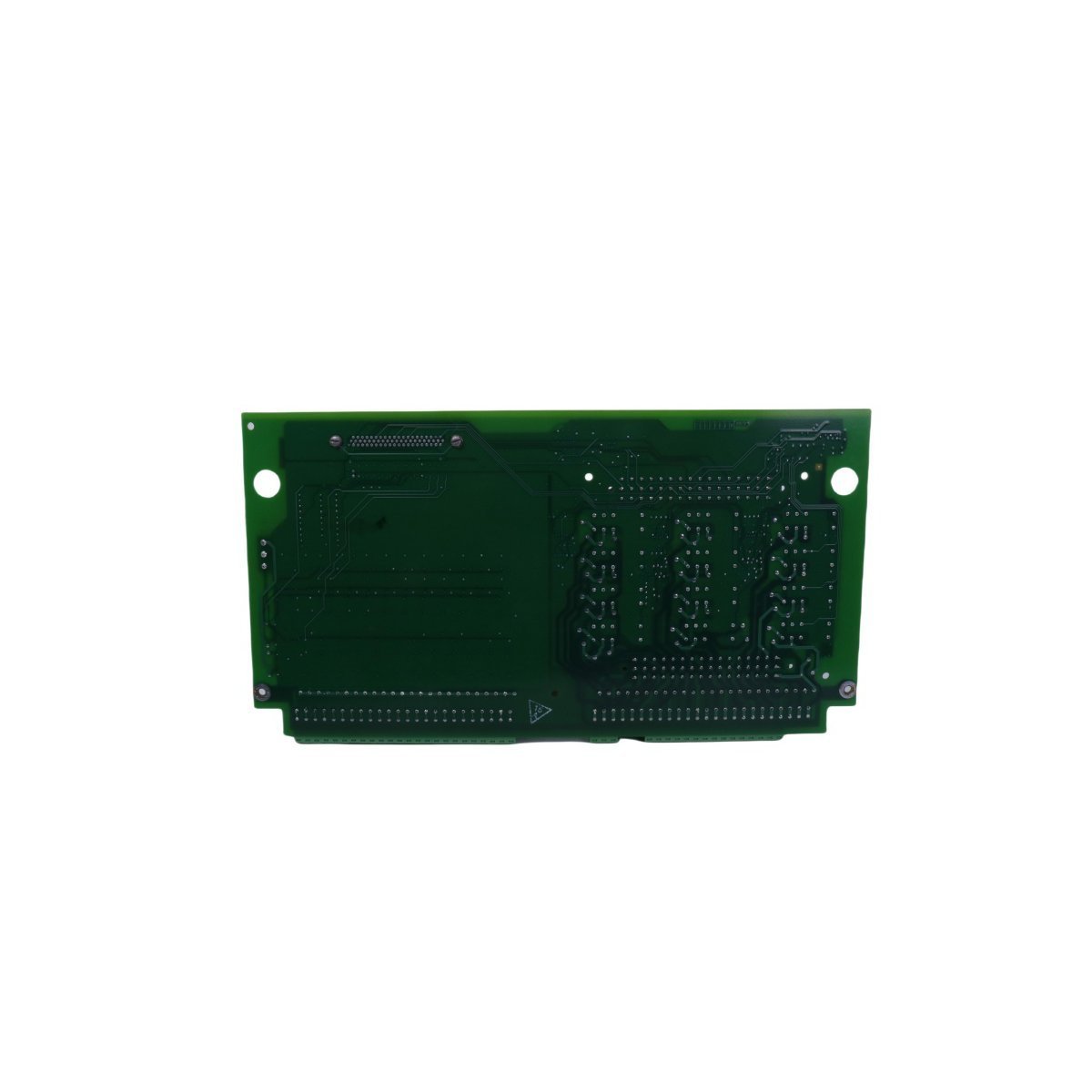
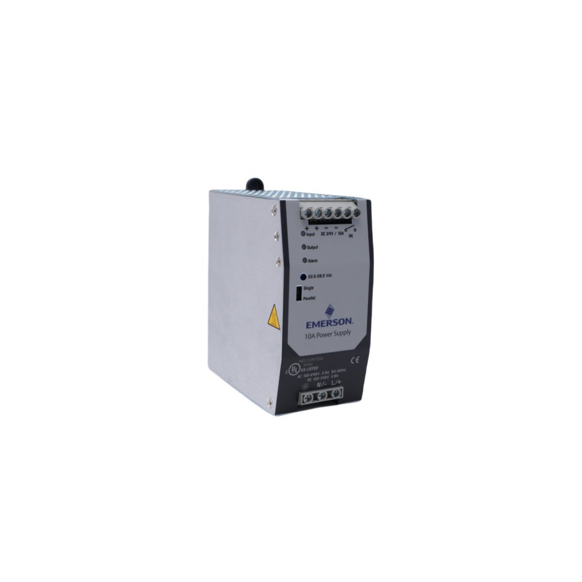
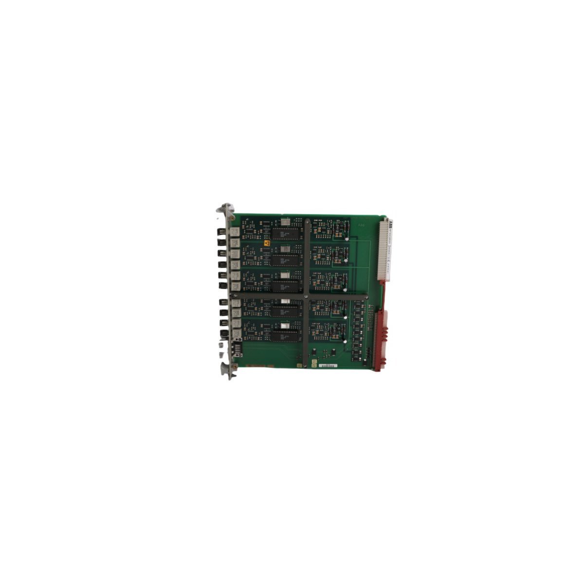
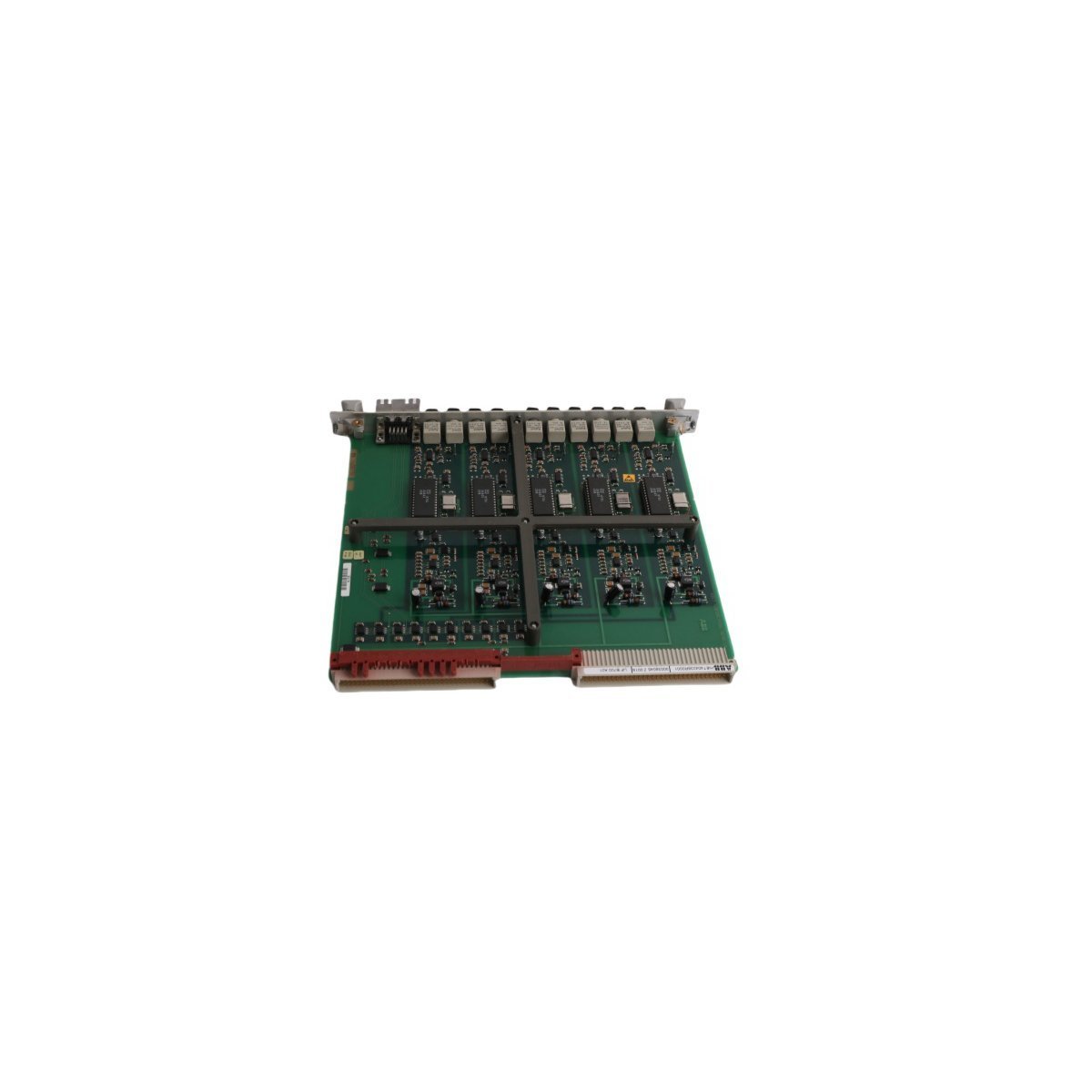
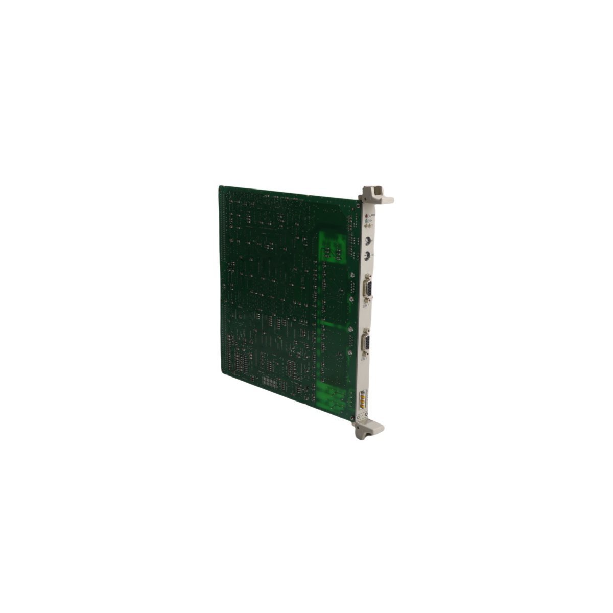
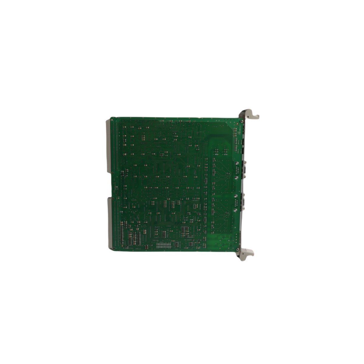
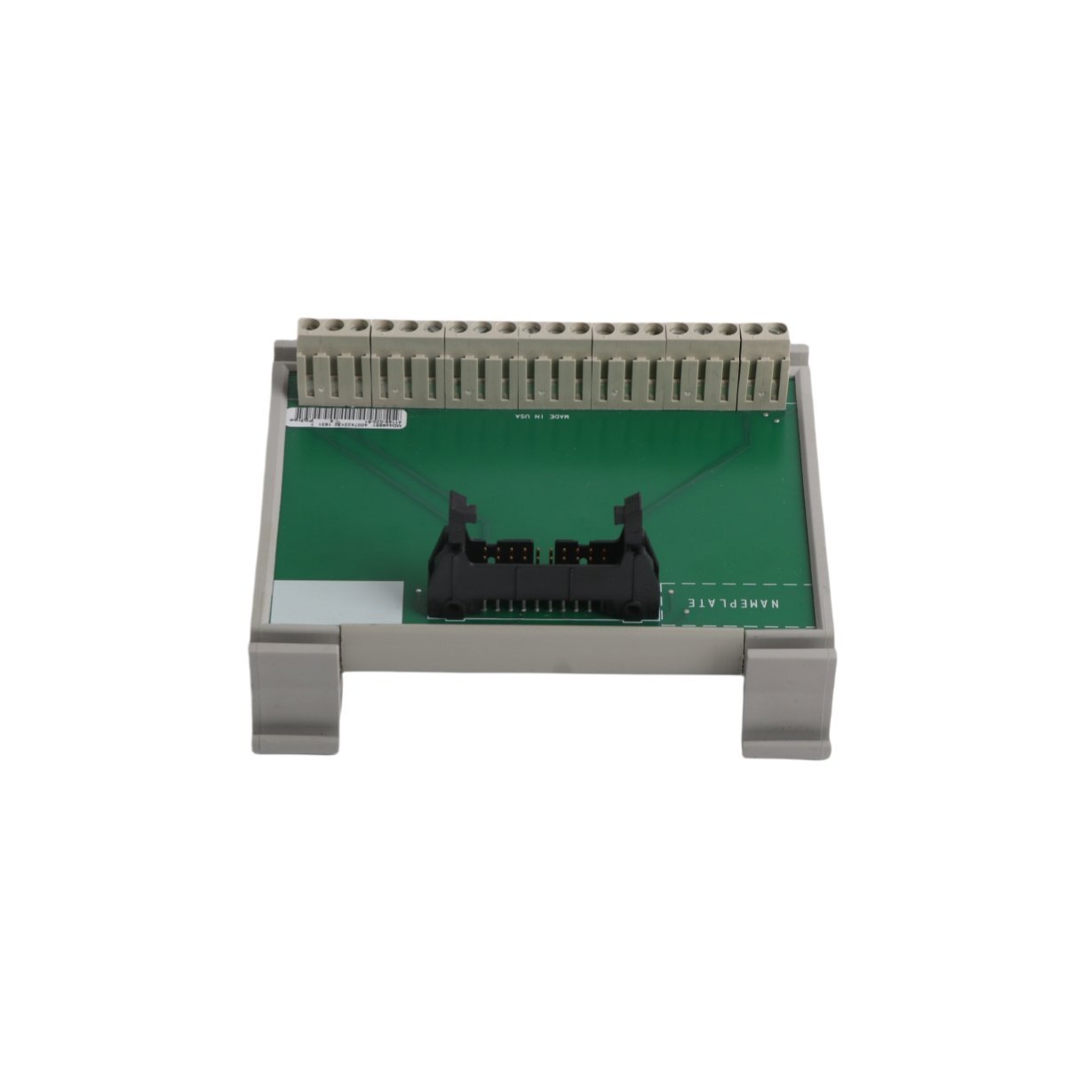
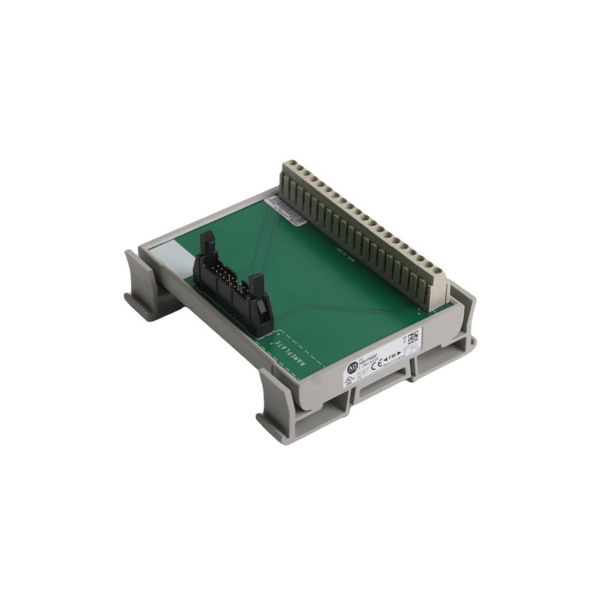
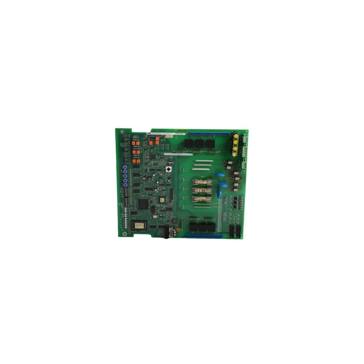
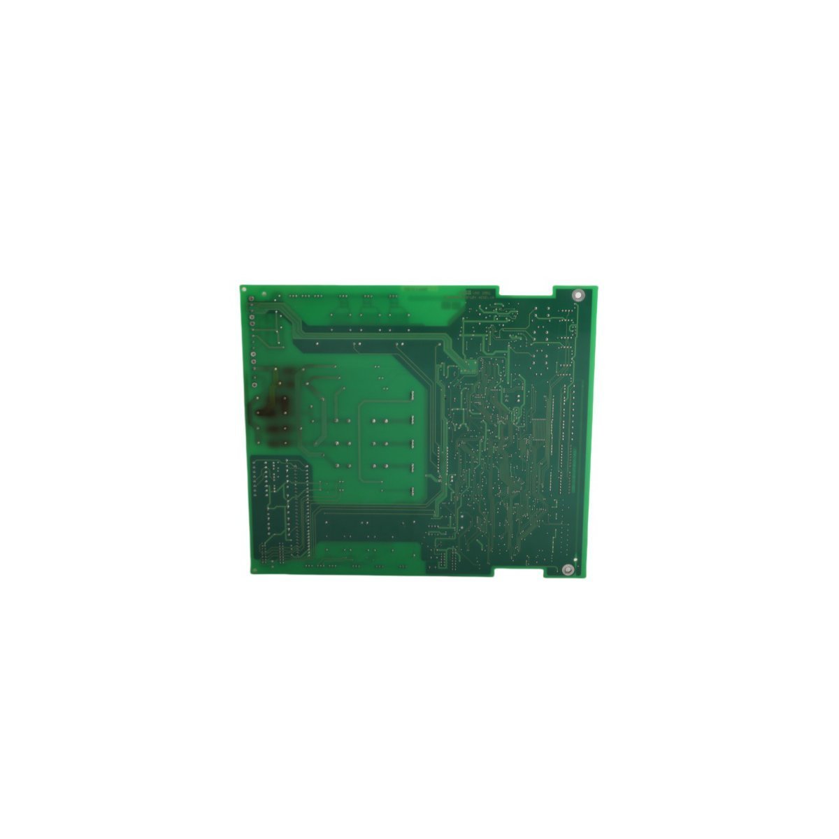
Emerson KJ3008X1-BA1 12P2293X052 Sequence Events Module
The Emerson KJ3008X1-BA1 12P2293X052, also cataloged as the KJ3008X1-BA1 Sequence Events Module, operates as a dedicated hardware component for high-resolution discrete event timestamping and digital state acquisition within Emerson DeltaV M-series I/O Subsystem platforms.
Hardware Specifications
| Parameter | Specification |
|---|---|
| Model | KJ3008X1-BA1 12P2293X052 |
| Brand | Emerson |
| Product Range | DeltaV M-series I/O Subsystem |
| Module Type | Sequence Events Module |
| Origin | USA |
| Weight | 0.28 kg |
| Dimensions | 4.3 x 12.5 x 10.5 cm |
| Operating Temp | -40 to 70 deg C |
| Power Consumption | 12 VDC at 150 mA (local bus) |
| HS Code | 8537101190 |
| Lifecycle Status | Discontinued (Dec 31, 2018) |
Process Control and DCS Characteristics
- Interfaces directly with 4-20 mA HART loop protocol architectures and discrete field contacts via DeltaV I/O carrier backplanes.
- Features integrated channel-to-channel isolation to prevent ground loop noise propagation across adjacent signal paths.
- Leverages hardware-level cold junction compensation (CJC) algorithms across paired terminal blocks during thermal transients.
- Executes millisecond-accurate sequence-of-events logging to capture contact state transitions before transferring data to DeltaV controllers.
Frequently Asked Questions
Q: Does the KJ3008X1-BA1 module support removal under power within a DeltaV I/O carrier?A: Yes, the module supports Removal and Insertion Under Power (RIUP) without disrupting communications or field wiring on adjacent I/O cards.Q: How is time synchronization maintained across multiple Sequence Events Modules?A: Time synchronization is maintained via the DeltaV M-series local bus backplane driver, which aligns module event counters with the system master clock.Field Installation Guidelines
- Secure the module onto the dedicated DeltaV M-series I/O carrier terminal block slot until the retention latch locks fully.
- Ground all field cable shields at the carrier earth bus bar using short, low-impedance conductor connections.
- Maintain separation between low-voltage field contact signal lines and high-voltage power conduits inside the enclosure.