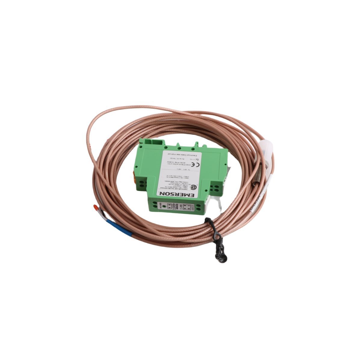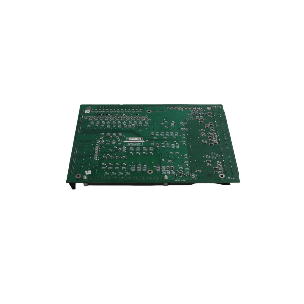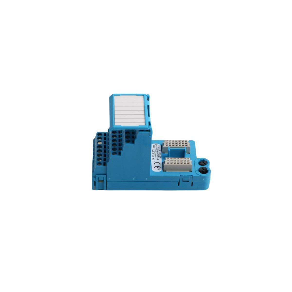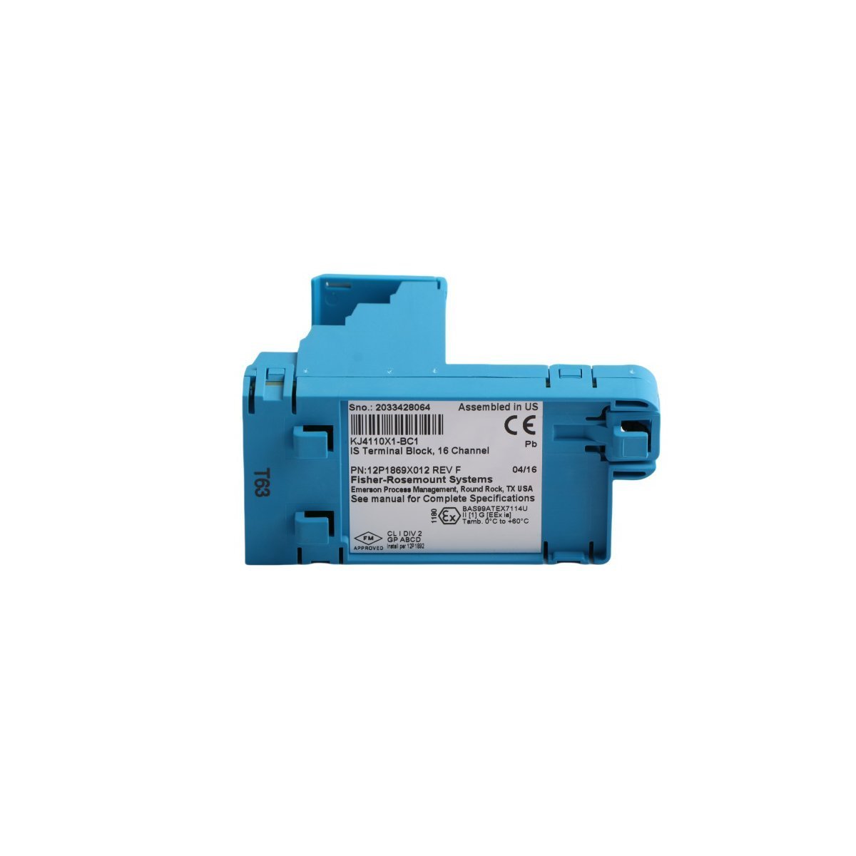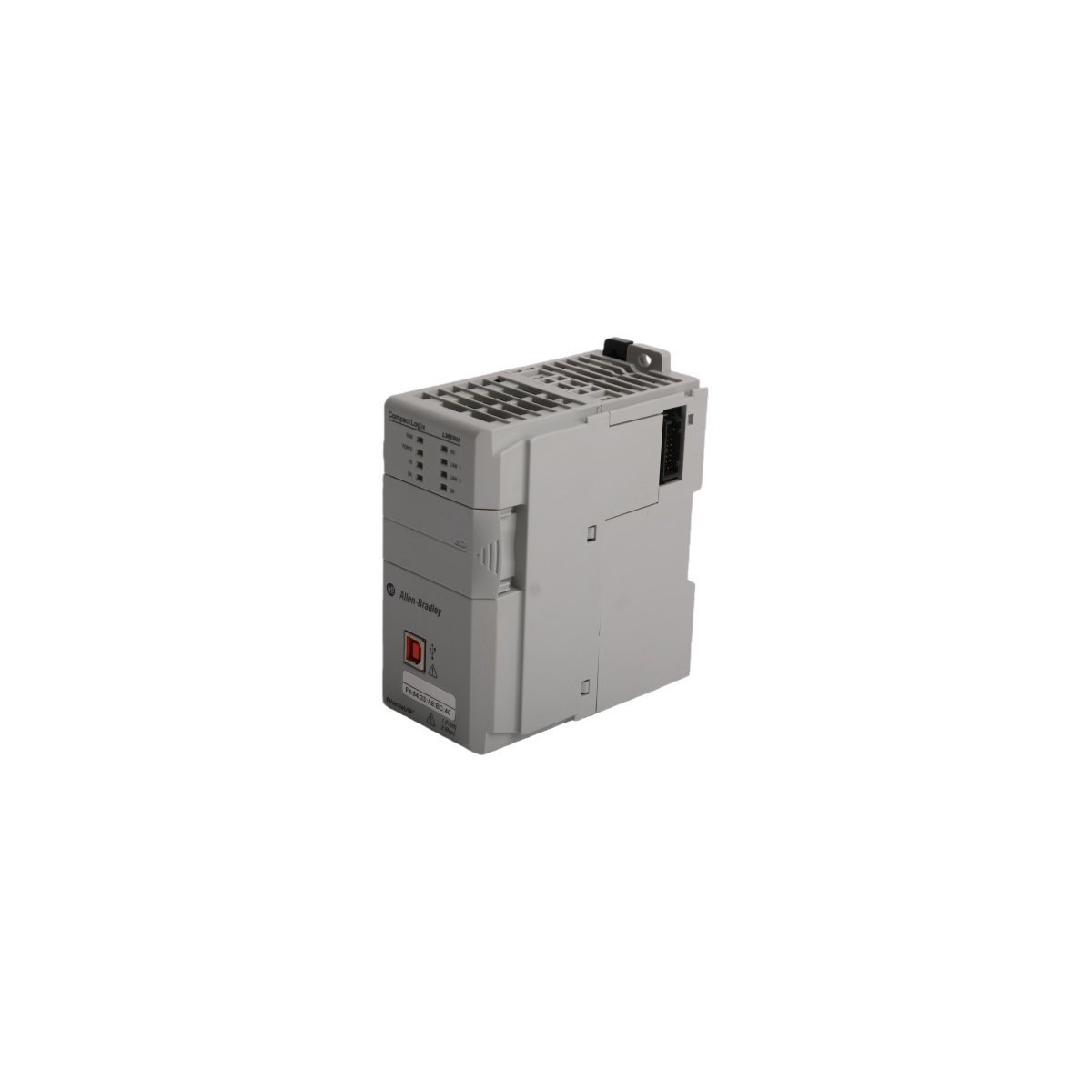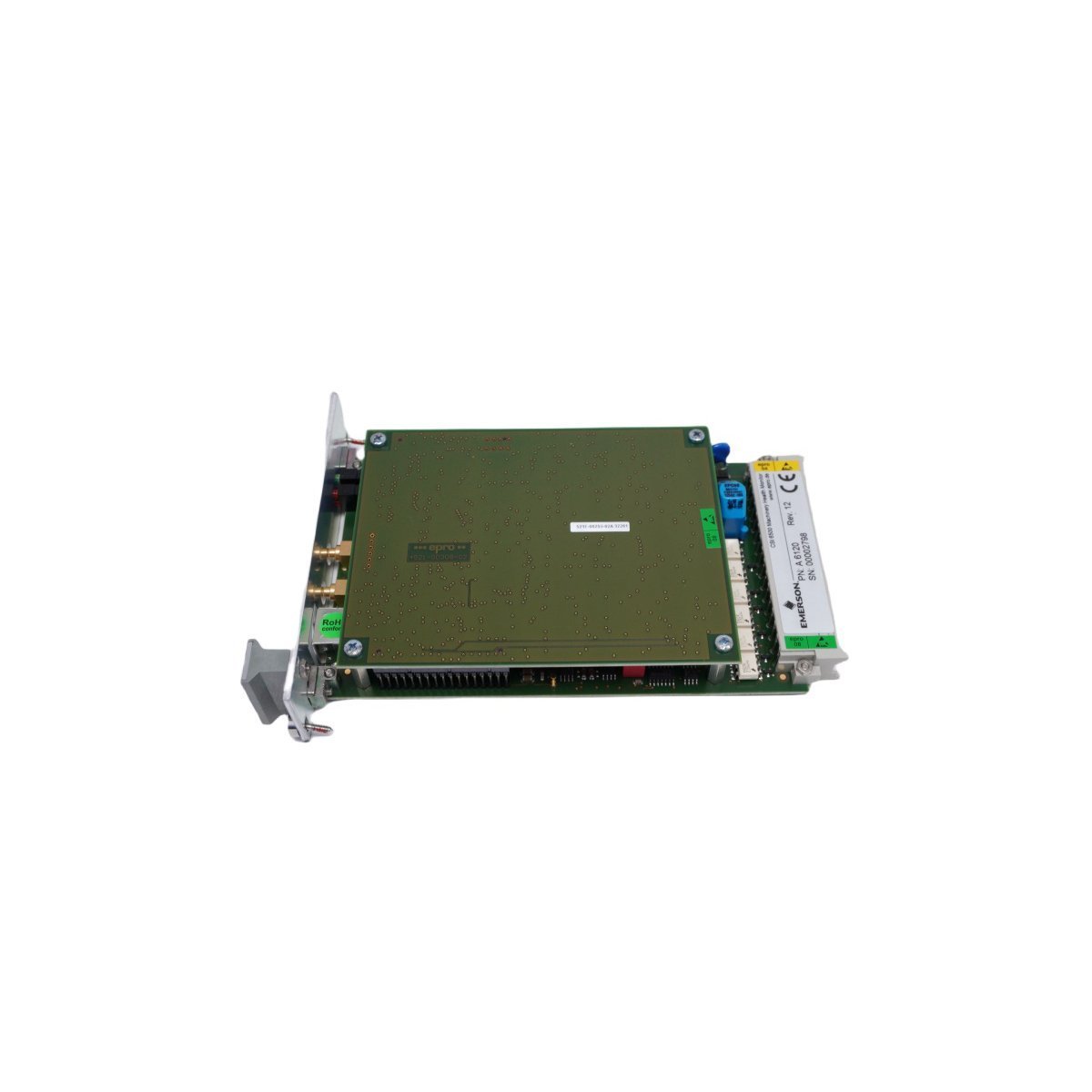
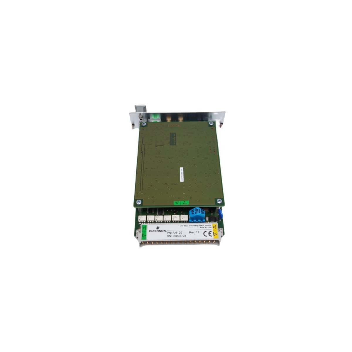
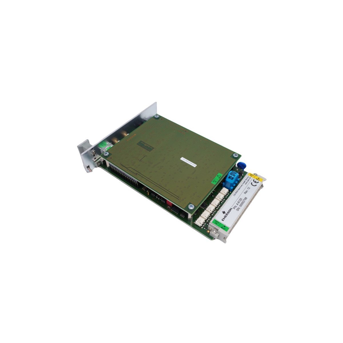
The EMERSON A6120 case seismic vibration module safeguards large industrial rotating equipment. Brand New, original factory stock, ready for Global Shipping. Prevent machinery downtime—Request a technical product quote today.
The EMERSON A6120, also cataloged as the A6120 Vibration Monitor Module, functions as a high-density asset protection component within the CSI 6500 Machinery Health Monitor platform. This module captures absolute casing vibration signals from seismic sensors (accelerometers or velocity transducers) to protect large rotating machinery—such as steam turbines, gas turbines, pumps, and compressors—from critical mechanical failures.
Hardware Specifications
Parameter
Specification
Model Number
A6120
Manufacturer
EMERSON (CSI 6500 / AMS Series)
Origin
USA
Weight
0.30 kg
Dimensions
3.1 cm x 18.9 cm x 12.9 cm
Operating Temperature
-20 to 65 deg C
Module Type
Case Seismic Vibration Monitor Module
System
DCS / Machinery Health Monitoring (TSI)
HS CODE
8537101190
Discontinued Date
Dec 31, 2018
Communication Service
Internal rack bus / Ethernet router interface integration
Machinery Diagnostics & Signal Architecture
The A6120 module continuously processes structural casing shakes, executing real-time fast Fourier transform (FFT) analysis to monitor fundamental frequencies associated with structural looseness, imbalance, misalignment, and rolling-element bearing degradation. The module provides programmable hardware alert and danger threshold relays that link directly into emergency trip logic circuits, safeguarding critical industrial assets against catastrophic failure modes without relying on software network processing.
Frequently Asked Questions
Q: What type of field sensors are natively compatible with the A6120 seismic monitor module?
A: The module interfaces directly with standard industrial piezoelectric accelerometers and electrodynamic velocity sensors mounted externally to the bearing housings or machinery shells.
Q: Is this card hot-swappable in an active CSI 6500 rack system?
A: Yes, but with precautions. While the rack power can remain active, removing this card will open its hardware interlock relays and strip that specific machine casing segment of protection. Always place the associated machinery protection loops into “Bypass” or “Service Mode” at the control console before extracting the module.
Field Installation Guidelines
Insert the A6120 module straight along the card guide rails inside the CSI 6500 chassis, firmly pushing until the front faceplate satisfies flush configuration with the rack edge.
Tighten the integrated knurled panel screws completely by hand or tool to secure mechanical chassis grounding.
Run sensor raw signal wires via twisted-pair shielded cables directly to the terminal blocks, keeping them separate from power and high-voltage motor feeds.
Verify sensor bias voltage via the front panel test ports during initial commissioning phases to ensure field wiring and transducer circuit integrity.
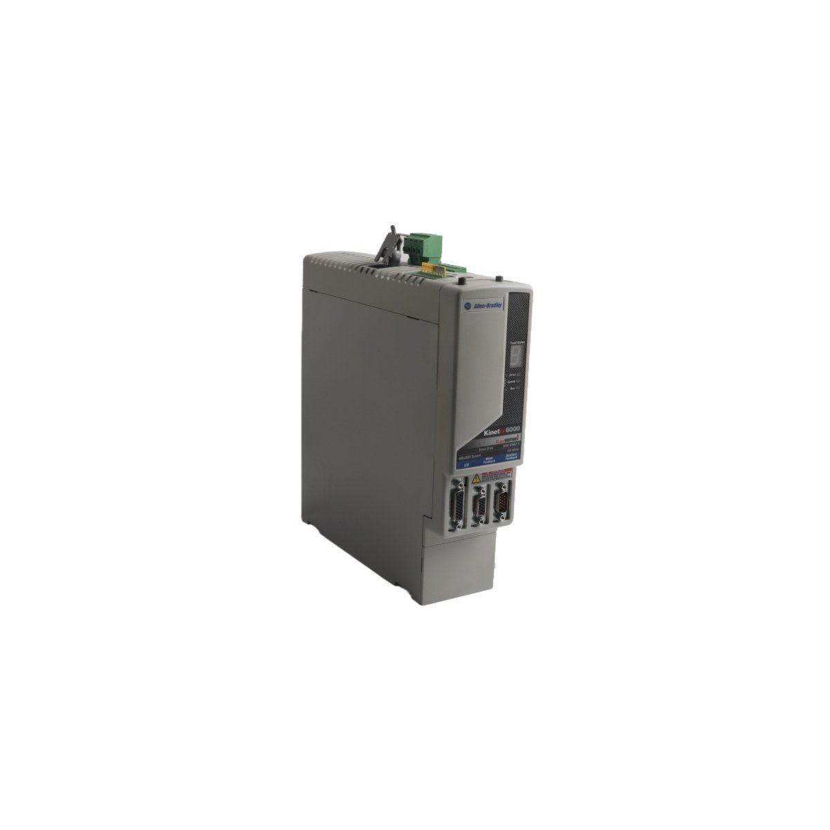
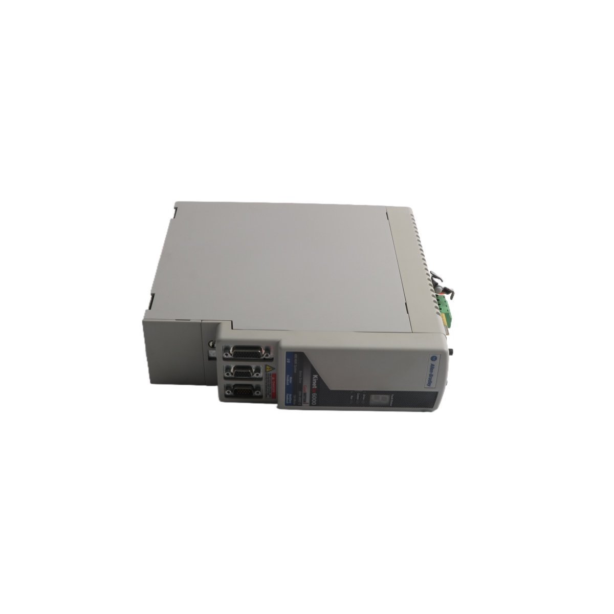
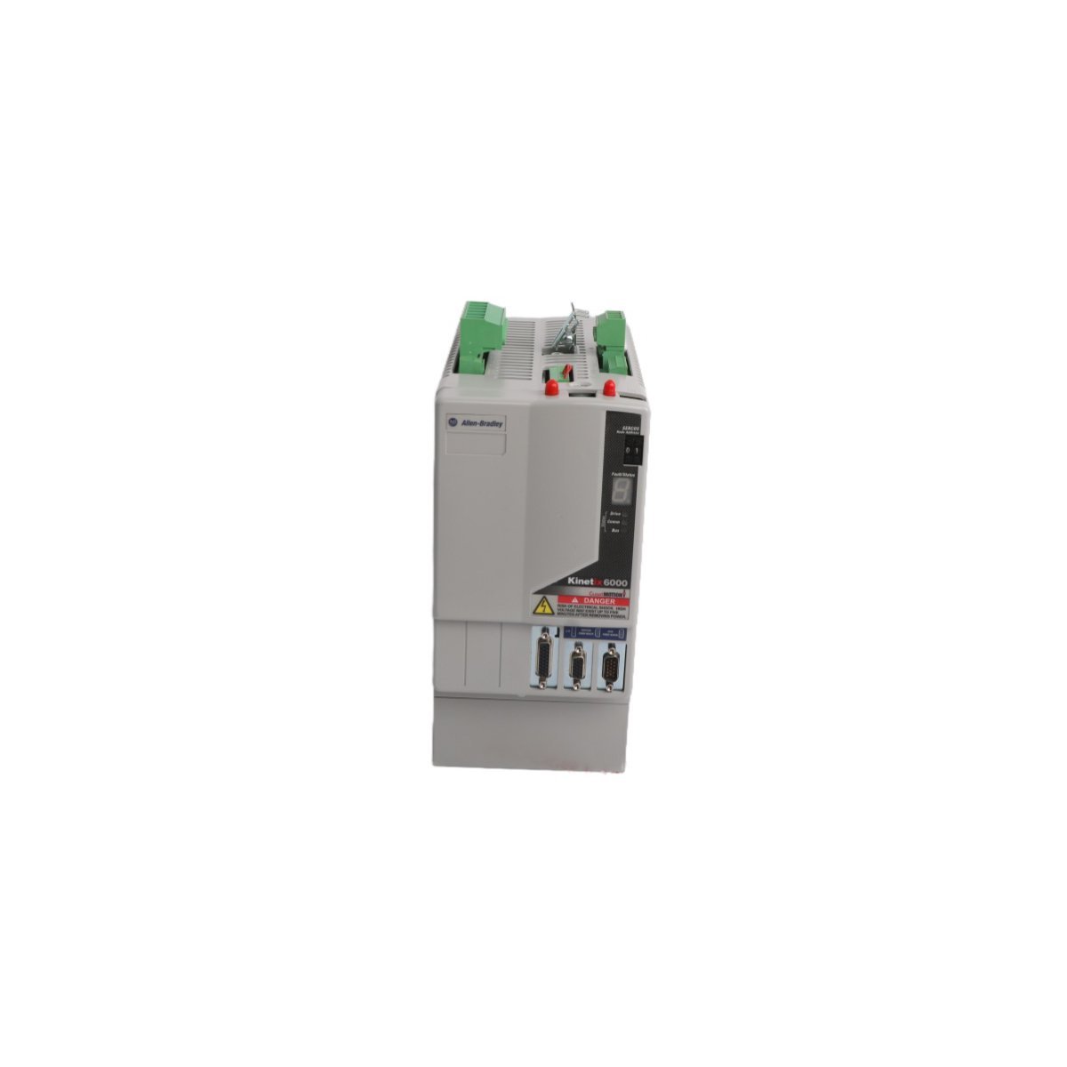
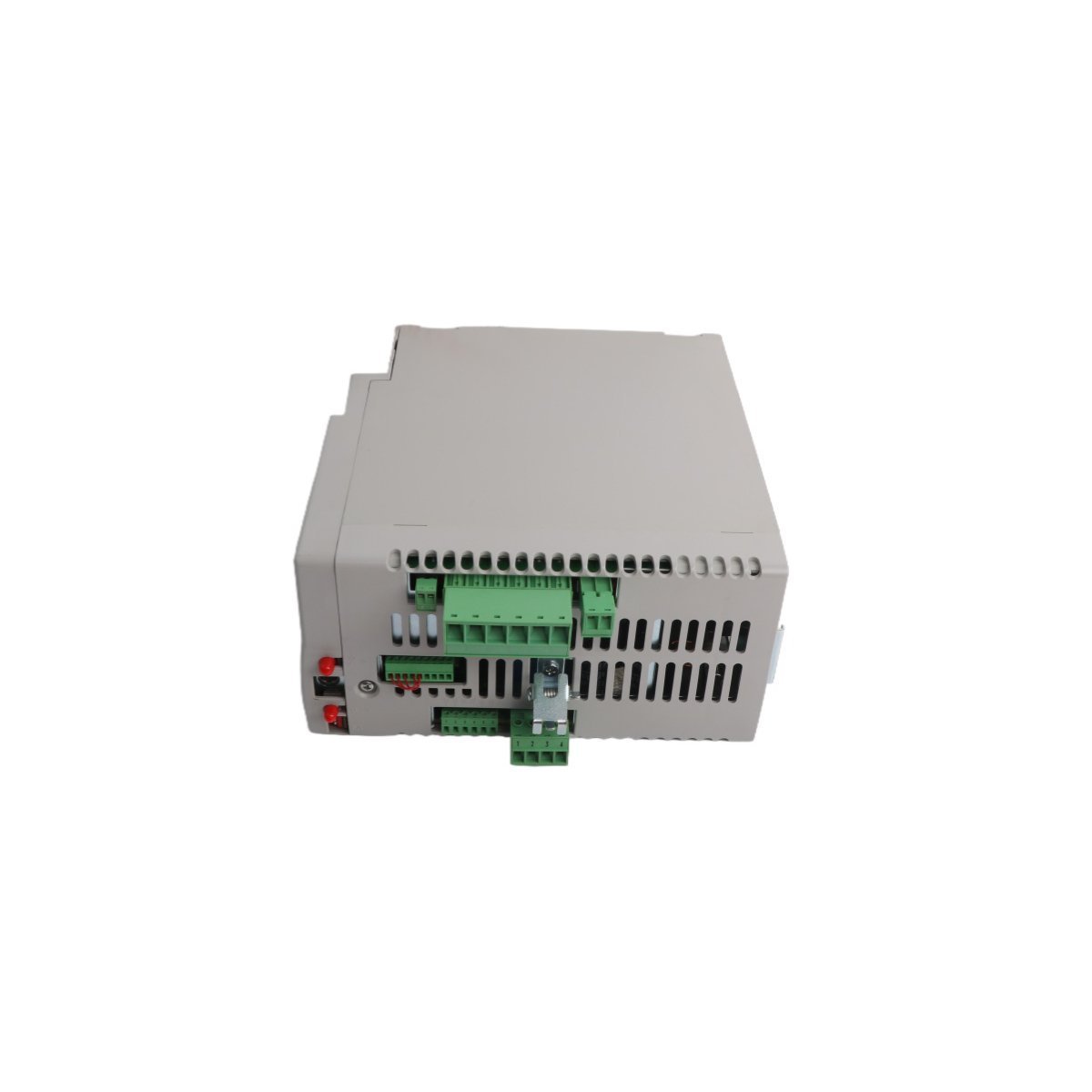
The Allen-Bradley 2094-BC01-M01-S, also cataloged as the 2094-BC01-M01-S Integrated Axis Module, operates as a dedicated hardware component for high-speed motion control and power regulation within Kinetix 6000 multi-axis drive platforms.
Hardware Specifications
Parameter
Specification
Model
2094-BC01-M01-S
Brand
Allen-Bradley
Origin
USA
Weight
0.9 kg
Dimensions
3.5 cm x 13 cm x 14.5 cm
Operating Temp
Standard industrial range
Power Consumption
3.9 kW (Total)
Inverter Current
9 A
Input Voltage
360-480 V AC
PLC and Drive Control Characteristics
The 2094-BC01-M01-S incorporates backplane bus communication velocity protocols, enabling deterministic synchronization between the converter and inverter stages. The architecture facilitates I/O density scaling within the drive cabinet, allowing for coordinated power distribution across multiple integrated axes. Furthermore, the module supports firmware flash compatibility, which ensures that internal logic remains aligned with system-wide motion control requirements. This design enables precise control over power threshold excursions and maintains stable torque output during transient loading conditions.
Frequently Asked Questions (FAQ)
Q: What are the primary communication requirements for the SERCOS interface on this module?A: The SERCOS interface requires fiber optic media configured in either linear or ring topologies; ensure that the fiber ends are polished and properly seated in the transceivers to maintain signal integrity and avoid communication latency.Q: Can the Safe Torque Off (STO) function be bypassed if not required by the application?A: The STO circuit must remain closed via the designated safety input terminals to enable drive operation; if the safety function is not utilized, you must jumper these inputs according to the installation manual to permit the pulse-width modulation (PWM) output to the motor.
Field Installation Guidelines
To begin with, ensure all primary power is disconnected and the DC bus capacitors have reached a discharge state before you mount the module onto the power rail; subsequently, verify that the rear-facing power connectors align correctly to prevent pin deformation.
Furthermore, terminate all motor feedback cables using the appropriate shielded connectors; in addition, ensure the shield drain wire connects to the designated ground lug to minimize electromagnetic interference (EMI).
When configuring the SERCOS ring, route fiber optic cables with a sufficient bend radius to prevent signal attenuation; meanwhile, label each fiber connection to identify the transmit (Tx) and receive (Rx) paths clearly.
Finally, verify the input voltage range (360-480 V AC) matches the site supply before you apply power; by doing so, you ensure the internal power conversion stage functions within rated limits.
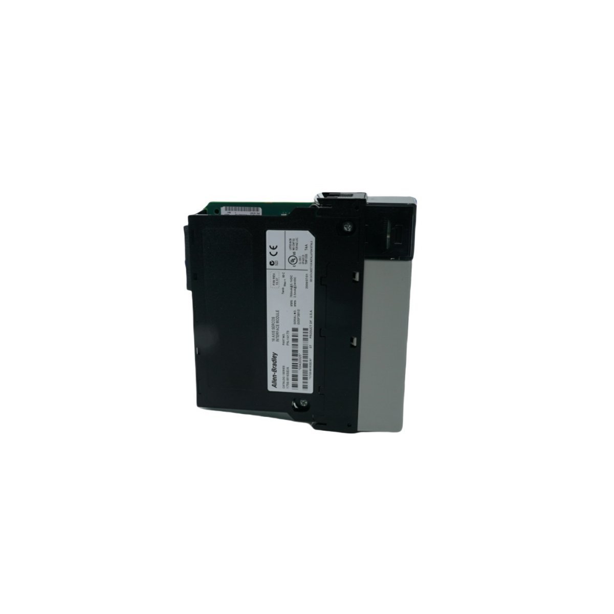
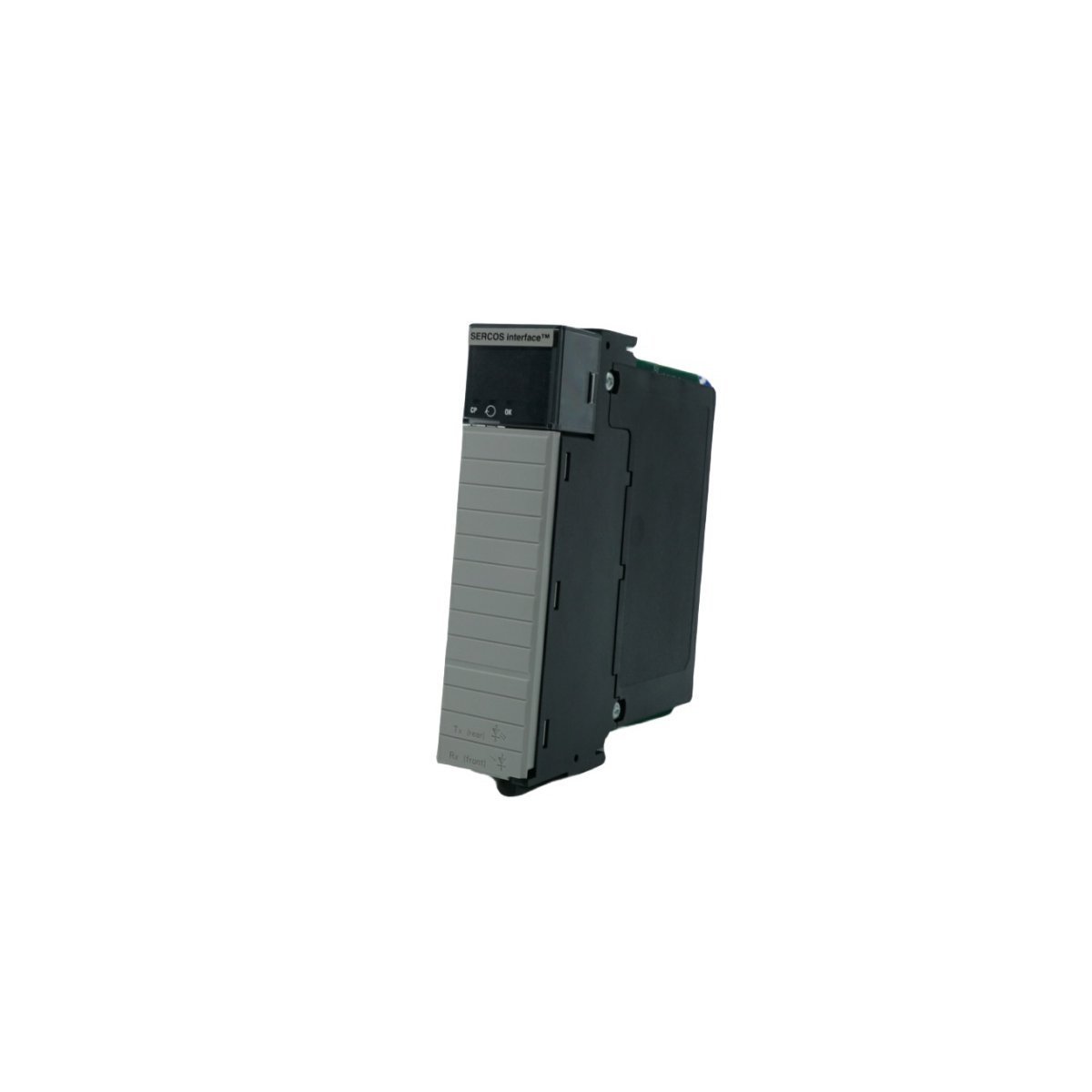
Configured for high-speed motion synchronization in ControlLogix systems, the Allen-Bradley 1756-M16SE (1756-M16SE SERCOS interface Module) provides direct physical and electrical execution for multi-axis servo drive command distribution.
Hardware Specifications
Parameter
Specification
Model
1756-M16SE
Brand
Allen-Bradley
Origin
USA
Weight
0.22 kg
Dimensions
3.5 cm x 14 cm x 14.5 cm
Operating Temp
Standard industrial range
Power Consumption
Backplane dependent
Data Rate
4 Mbps or 8 Mbps
Axis Capacity
16 axes per module
PLC Control and Communication Characteristics
The 1756-M16SE utilizes high-speed backplane bus communication velocity to manage deterministic data exchange between the ControlLogix CPU and remote servo drive nodes. By leveraging digital fiber-optic SERCOS interfaces, the module achieves I/O density scaling that minimizes signal propagation latency across 16 managed axes. Furthermore, the module supports firmware flash compatibility, which allows for site-specific motion algorithm updates without physical hardware replacement. This deterministic network structure ensures that position, velocity, and torque command loops maintain sub-millisecond synchronization even in high-density drive configurations.
Frequently Asked Questions (FAQ)
Q: What are the primary limitations when configuring the SERCOS ring topology for the 1756-M16SE?A: The ring topology is limited by the physical length of the fiber-optic cabling and the total number of connected nodes; you must ensure the total loop latency does not exceed the configured cycle time (0.5 ms or 1.0 ms) to maintain deterministic operation.Q: Is the 1756-M16SE module capable of hot-swapping within an active ControlLogix chassis?A: The module supports standard ControlLogix hot-swap procedures; however, removing the module will immediately drop the SERCOS ring communication, causing all connected servo drives to transition to their programmed fault state.
Field Installation Guidelines
To begin with, confirm the ControlLogix chassis backplane is powered down; subsequently, insert the 1756-M16SE into a designated slot and secure it using the integrated module locking screws to ensure proper backplane contact.
In addition, route the SERCOS fiber-optic cables following the ring or linear topology requirements; meanwhile, maintain the minimum bend radius of the fiber to prevent micro-fractures that induce signal loss.
Furthermore, ensure all fiber-optic connectors are clean and free of contaminants before insertion into the module transceivers; consequently, this prevents optical attenuation that could lead to intermittent link failures.
Finally, configure the module addressing and axis scaling within the control software; by doing so, you ensure the controller can successfully establish the SERCOS communication cycle with the downstream Kinetix drives.
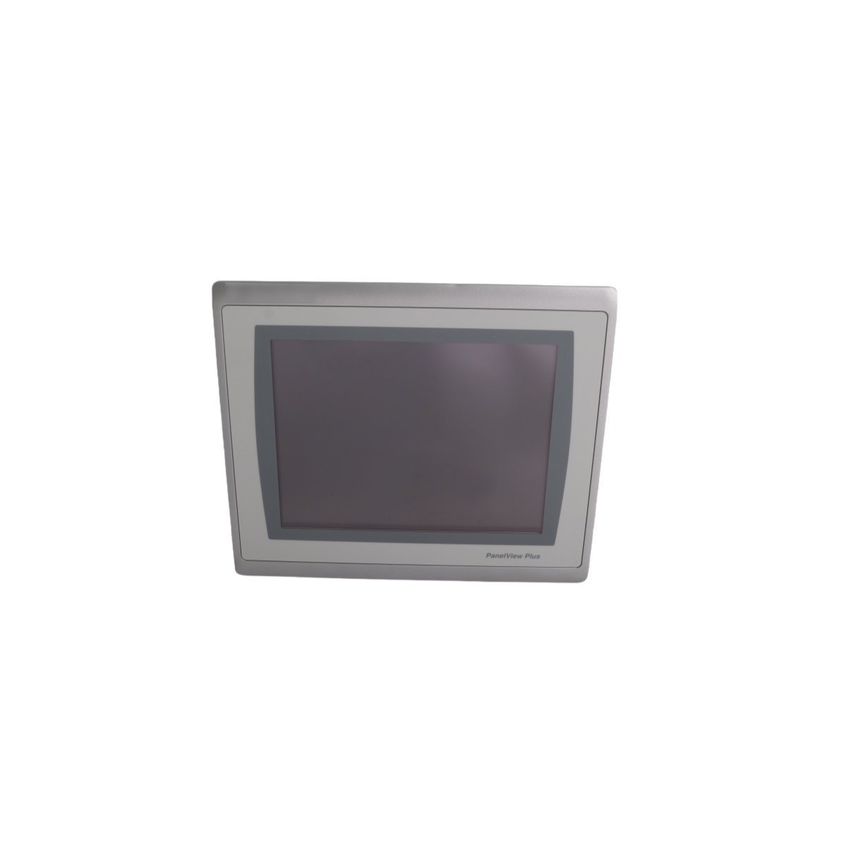
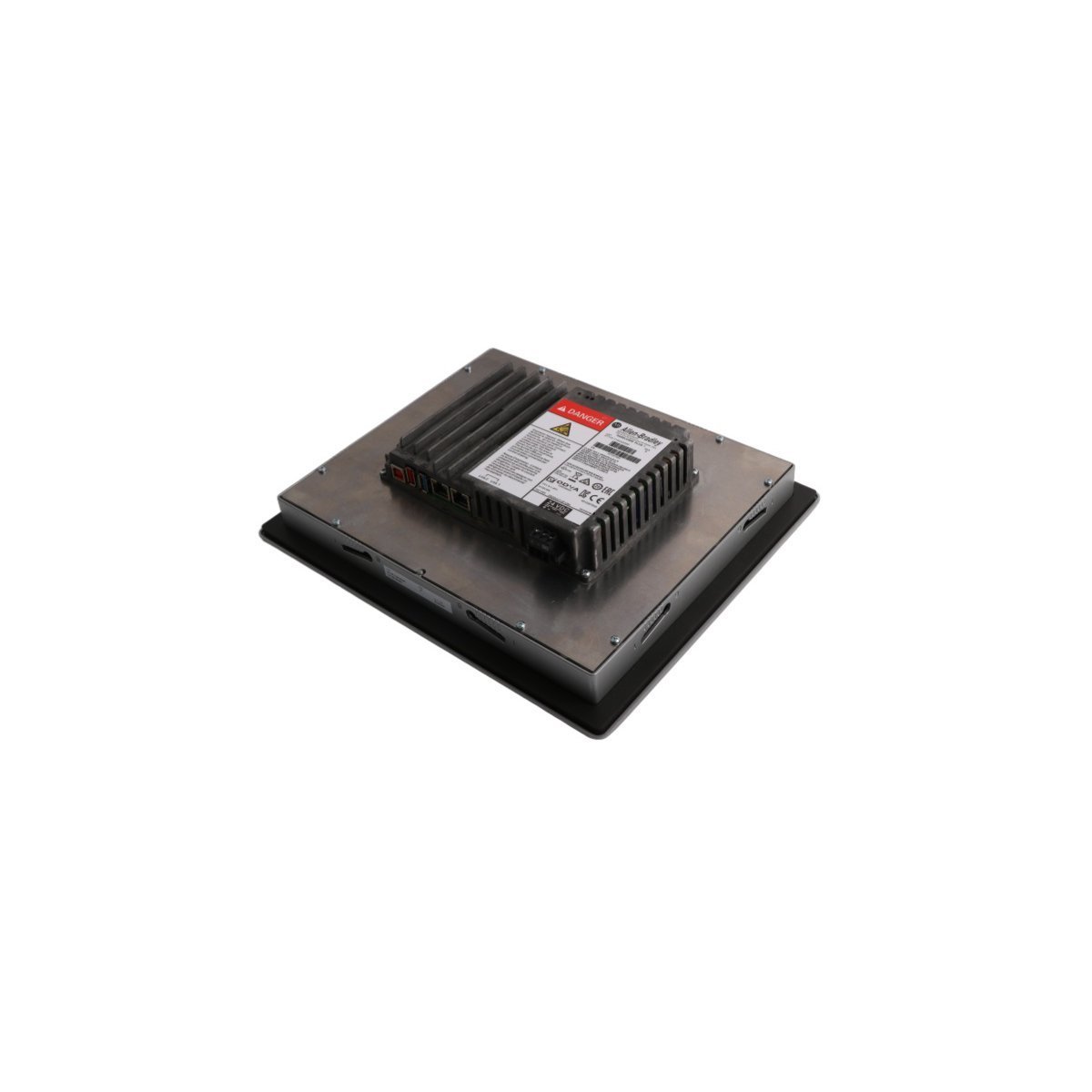
The Allen-Bradley 2711P-T10C22D9P serves as the primary 2711P-T10C22D9P PanelView Plus 7 Standard Color Terminal utilized to execute human-machine interface (HMI) visualization tasks across ControlLogix and CompactLogix platforms. Configured for direct panel monitoring and physical touch input control, the unit provides real-time graphic execution of process variables over local network nodes.
Hardware Specifications
Parameter
Specification
Model
2711P-T10C22D9P
Brand
Allen-Bradley / Rockwell Automation
Origin
USA
Weight
0.9 kg (Net) / 2.3 kg (Packaged)
Dimensions
3.5 x 13 x 14.5 cm (Chassis depth/profile variation)
Operating Temp
0 to +55 deg C
Power Input
24 VDC (PELV/SELV compliant)
Power Consumption
50 W maximum
Display Type
10.4-inch Color TFT (800 x 600 SVGA)
Memory
512 MB RAM / 80 MB Non-volatile user storage
Communication Ports
Dual 10/100 Base-T Ethernet (DLR), USB ports
Discontinued Date
June 30, 2016 (Catalog data reference)
Deterministic Network Routing & I/O Density Scaling
The HMI assembly utilizes integrated dual Ethernet ports configured for Profinet / EtherNet/IP deterministic networks, supporting Device Level Ring (DLR), linear, and star network topologies directly at the machine layer. This eliminates the necessity for external switches while protecting communication velocity against single-point physical cable breaks.Internal memory constraints control runtime graphic caching, allowing scaling for dense register structures mapped from local programmable automation controllers. Device settings and operational runtime parameters are updated via standard firmware flash compatibility tools or through FactoryTalk View Studio Machine Edition configuration routines.
Frequently Asked Questions
Q: What are the dual Ethernet port operational constraints regarding separate IP subnets?A: The integrated dual ports function as an embedded switch node supporting Device Level Ring (DLR) topology. Both physical interfaces share a single IP address and cannot be partitioned to bridge separate, independent subnets.Q: How is application data retention managed if primary 24 VDC input power is lost?A: The terminal utilizes onboard non-volatile flash memory to store the compiled runtime (.mer) application project file. System parameters and historical log data are committed directly to internal solid-state registers, removing battery dependency for file preservation.
Field Installation Guidelines
Enclosure Cutout Positioning: Prepare the panel door cutout using exact engineering template metrics. Ensure the surrounding sheet metal remains flat and free of distortion to establish uniform compression against the sealing gasket.
Torque Adjustments for Mounting Clips: Tighten the supplied panel mounting levers evenly in an alternating sequence. Do not exceed specified torque limits to avoid cracking the plastic bezel or compromise the NEMA/IP environmental seal.
Grounding Requirements: Connect the functional earth terminal on the rear power input connector block to a low-impedance master enclosure ground bar using a dedicated, short copper wire.
External Storage Handling: Insert or extract approved external memory cards only when the execution engine is idle to prevent database structure corruption within historical trending folders.
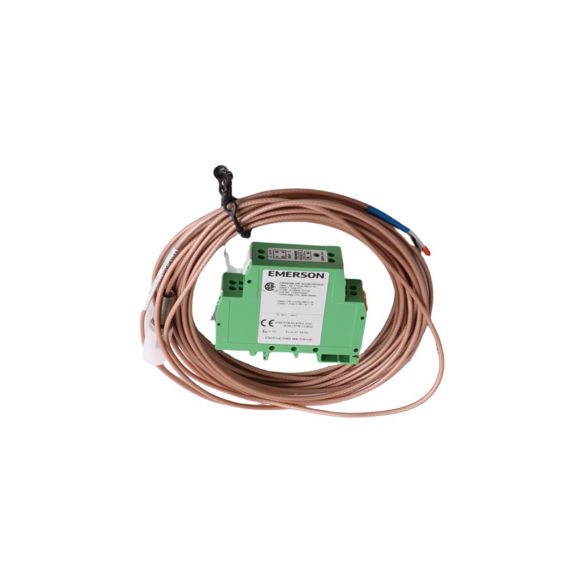
The EMERSON PR6423/00R-131 CON041 is a factory-original eddy current signal converter designed for high-accuracy displacement monitoring. Acquire this brand new, original stock component with secure worldwide shipping options and guaranteed hardware verification. Contact our technical team today to finalize your industrial replacement requirements.
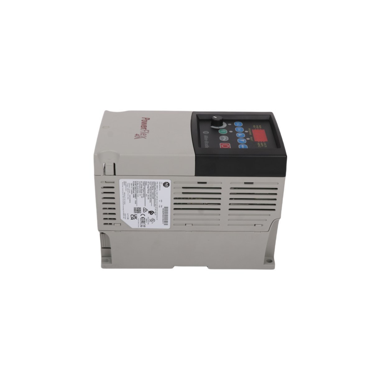
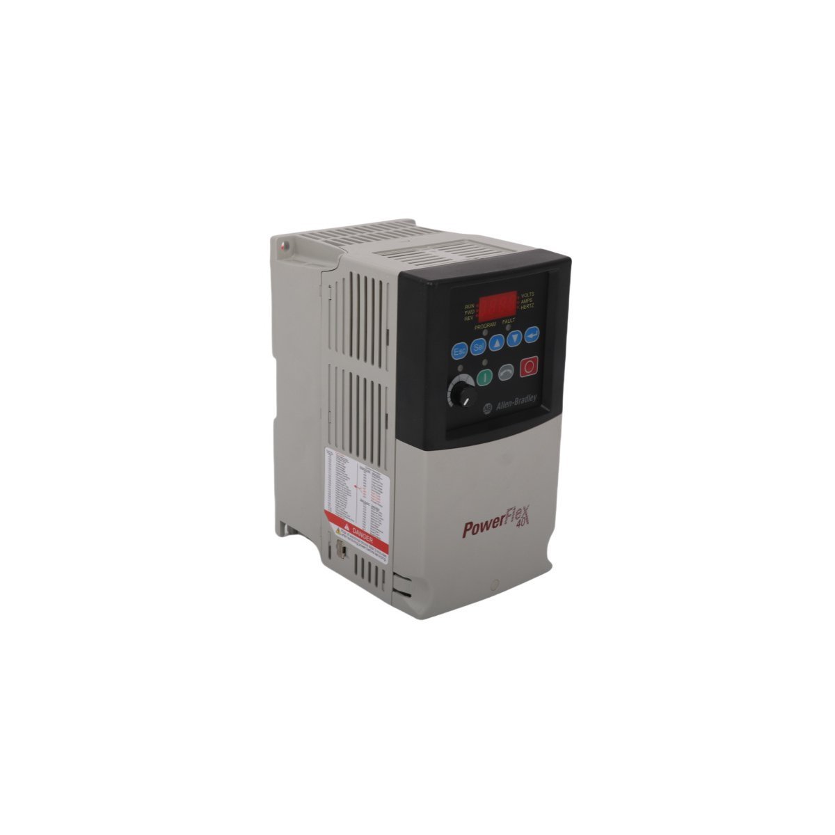
The Allen-Bradley 22B-A8P0N104 is a high-performance 2 HP sensorless vector variable frequency drive from the trusted PowerFlex 40 line. Secure this factory original surplus component featuring an integrated keypad, brake resistor, and DIN-rail mounting configuration. Order today for immediate international transit.
The Allen-Bradley 2094-BM02-S, also cataloged as the 2094-BM02-S Servo Drive, operates as a dedicated hardware component for multi-axis motion control execution within ControlLogix platforms. The hardware acts as a modular inverter node mounted directly onto a shared integrated power rail system. It modulates raw DC link energy into high-frequency pulse-width modulation (PWM) power vectors to regulate the angular positioning, velocity, and torque outputs of synchronized permanent magnet synchronous motors.
Industrial Control & Deterministic Driving Network
The Allen-Bradley 2094-BM02-S interacts directly over backplane bus communication velocity networks to achieve microsecond-level synchronization across adjacent drive modules. The hardware features deterministic network compatibility, letting control processors command motion trajectories with minimal jitter. It supports peak enhancement technology, scaling the nominal inverter output profile from a standard 150% threshold up to 250% during peak torque demands. This scaling permits rapid rotor acceleration and deceleration profiles without triggering overcurrent trips. Integrated Safe-Torque Off (STO) hardware circuits provide independent physical galvanic control paths, disabling gating signals to the output power transistors to prevent unexpected motor rotation during active maintenance states.
Frequently Asked Questions
Q: What are the backplane current and configuration limits when expanding axis modules on a single rail?A: The module must be inserted into an authorized Kinetix 6000 power rail, supporting up to seven axis modules alongside one master power module. The cumulative peak current draw must not exceed the structural rating of the shared copper backplane link.Q: Is this hardware compatible with live hot-swapping procedures?A: No. The shared 650 VDC bus lines pose arc-flash and component damage hazards. System DC bus voltage must be entirely drained and verified below safe thresholds before seating or unseating the module from the rail structure.Q: Can the internal 115 Ohm shunt resistor handle high-inertia braking loads?A: The internal shunt resistor is designed for short-duration thermal dissipation. High-inertia or cyclic deceleration applications require an external, isolated shunt module to prevent DC bus overvoltage faults.
Field Installation Guidelines
Enclosure Clearance & Thermal Profile: Maintain a minimum enclosure installation depth of 10.7 inches. Ensure unimpeded vertical ventilation spacing above and below the module chassis to prevent heat sink thermal saturation.
Cable Separation Architecture: Physically isolate unshielded high-voltage power cables, including motor leads and shunt resistor lines, from low-level digital feedback encoder loops and communication wires to suppress cross-talk.
Shielding and Ground Boundary: Terminate all motor cable shields at the designated grounding clamp on the power rail base. Maintain a low-impedance ground plane across the entire mounting subpanel.
Overcurrent Protection: Install specified circuit breakers or high-speed semiconductor fuses upstream of the main power distribution block to guard the internal solid-state components against phase-to-phase short circuits.
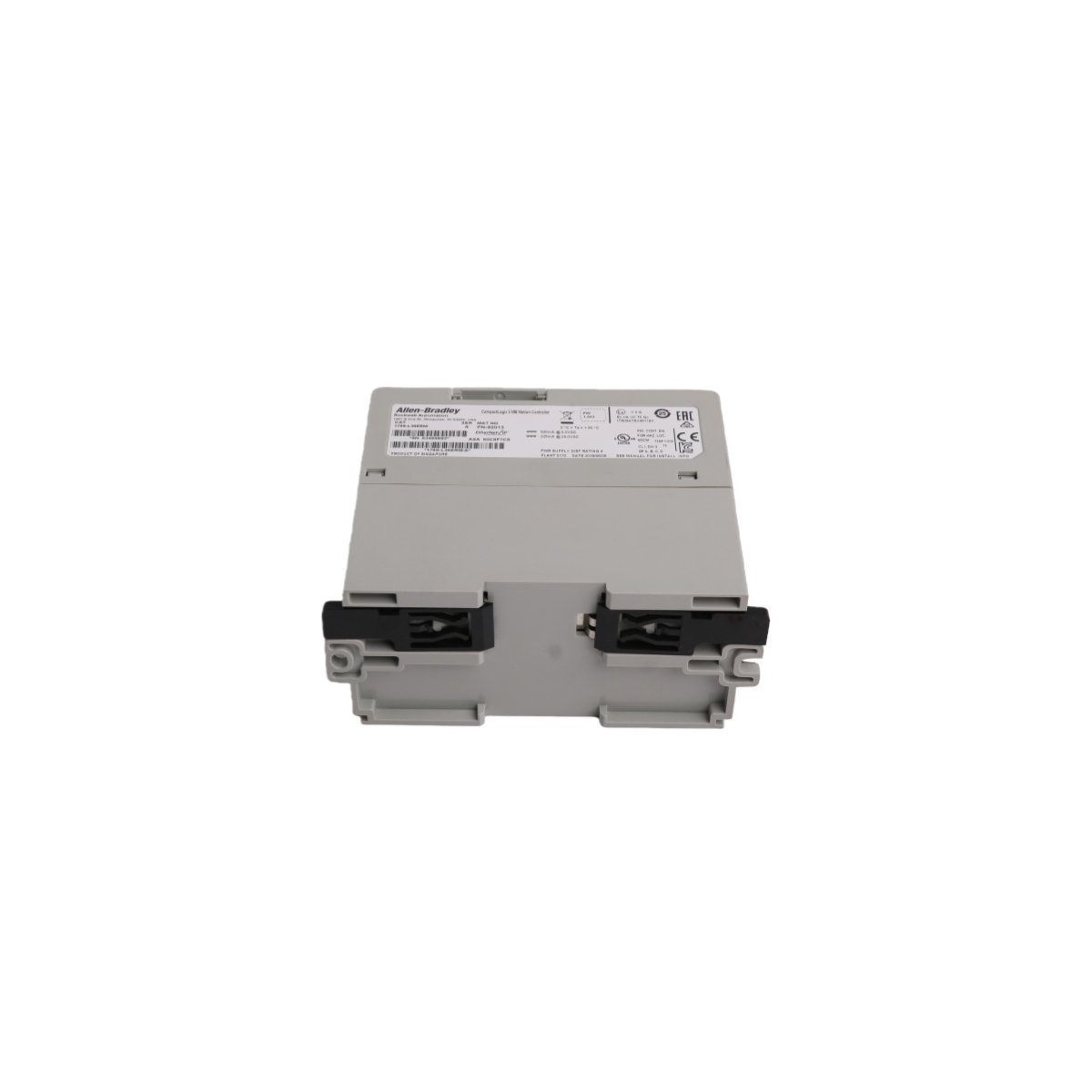
The Allen-Bradley 1769-L36ERM is a CompactLogix 5370 PAC processor featuring 3 MB user memory and 16-axis motion control. Brand New, Original Stock, ready for worldwide distribution.
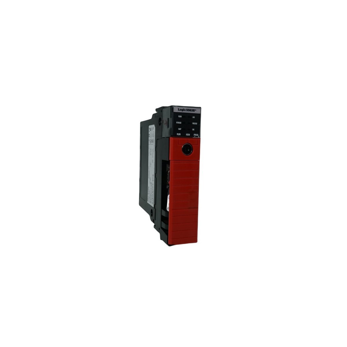
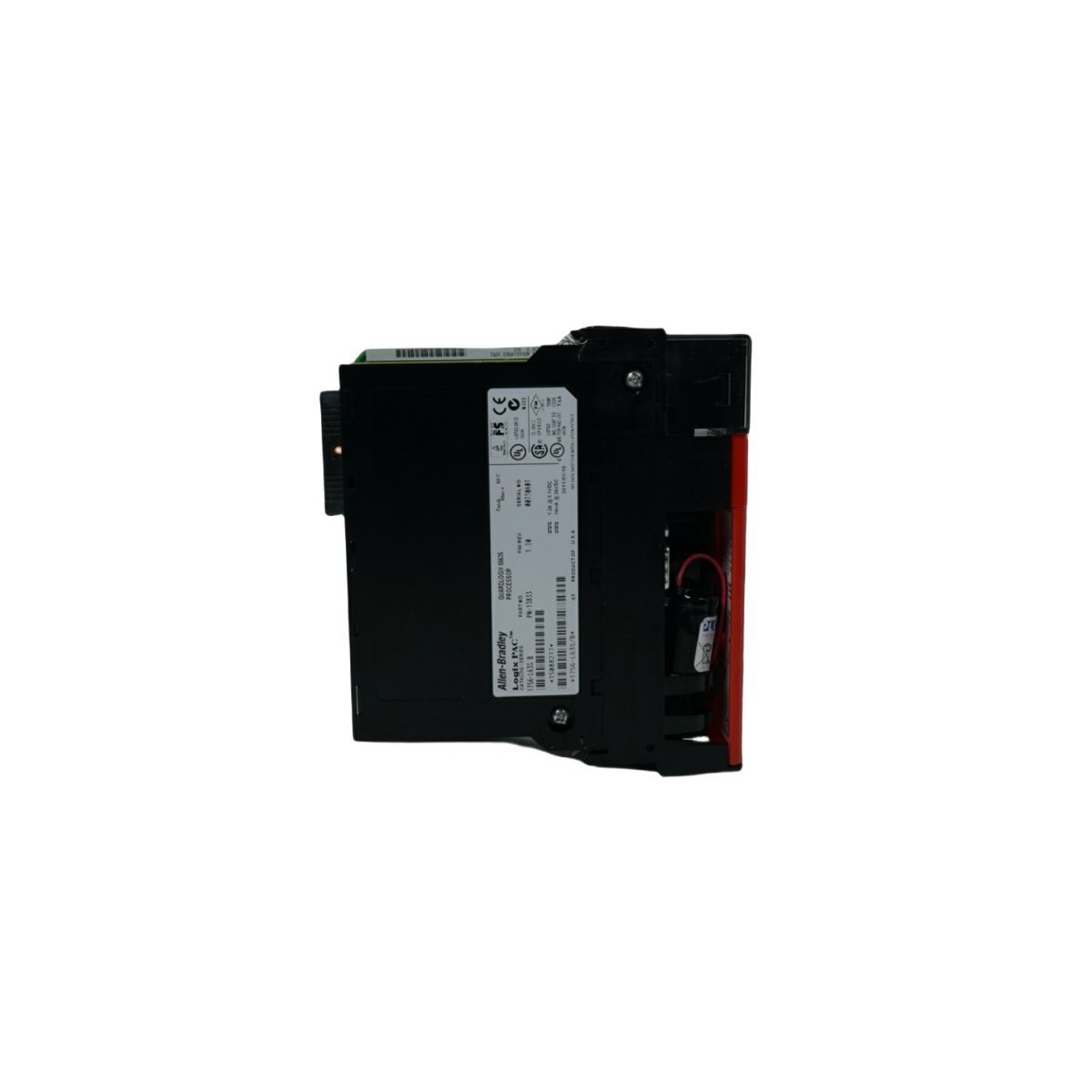
The Allen-Bradley 1756-L63S is a ControlLogix GuardLogix safety controller featuring 8MB user memory. Brand New, Original Stock, available now for global distribution.
The ABB PM864AK01 (3BSE018161R1) is a high-speed MPC862 processor unit designed for AC 800M and 800xA control systems.It features 32MB RAM, dual Ethernet ports, and supports up to 96 I/O modules, providing reliable real-time execution for demanding industrial automation tasks
We are committed to protecting your privacy. The information collected here is strictly used to provide the requested quotes, technical support, and relevant industrial automation solutions.