Sale!
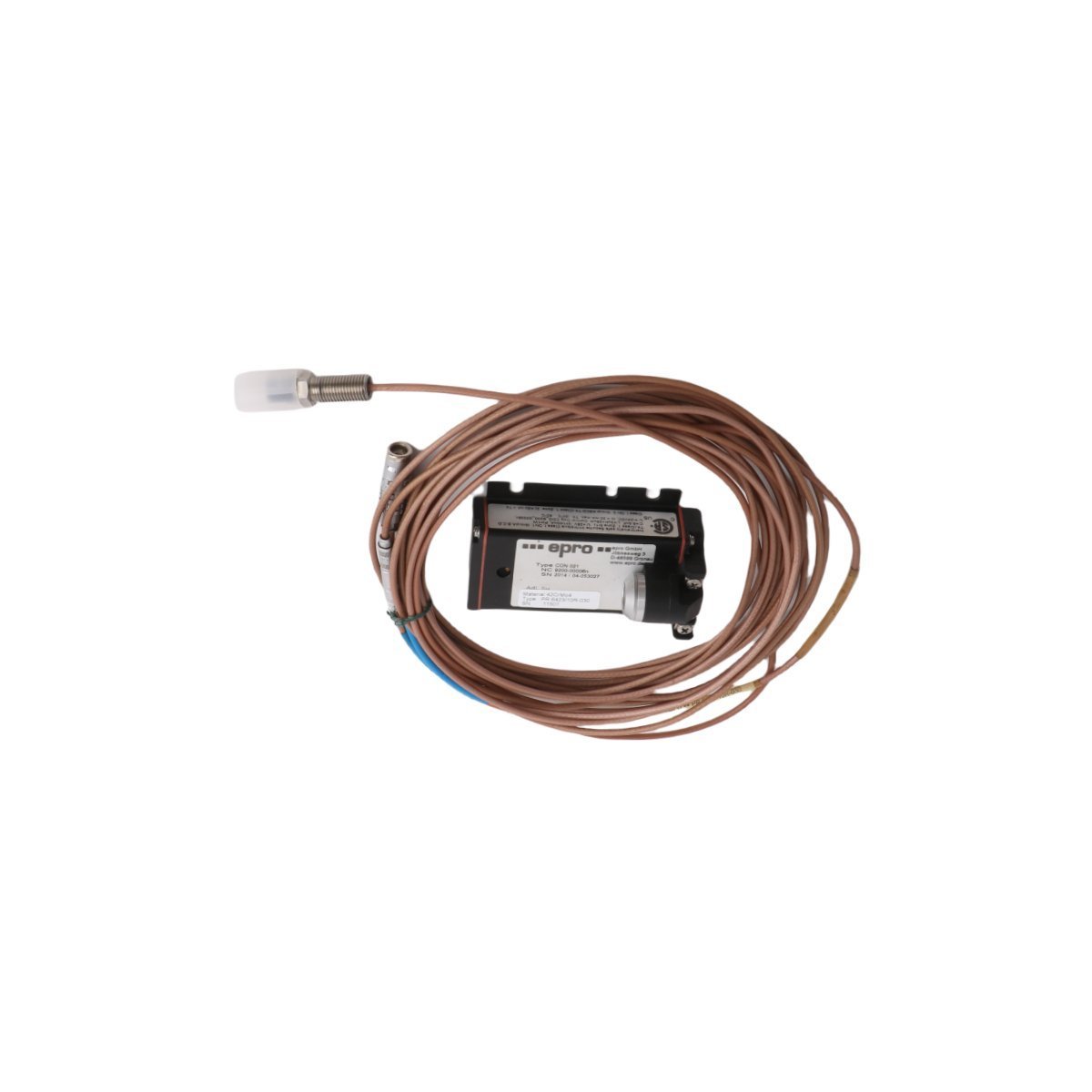
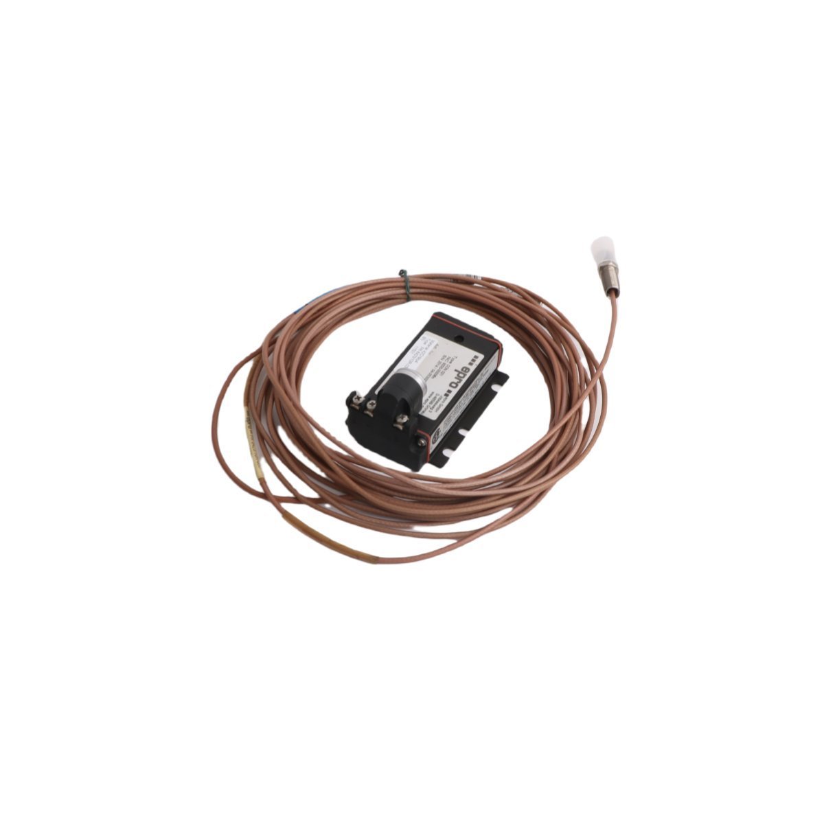
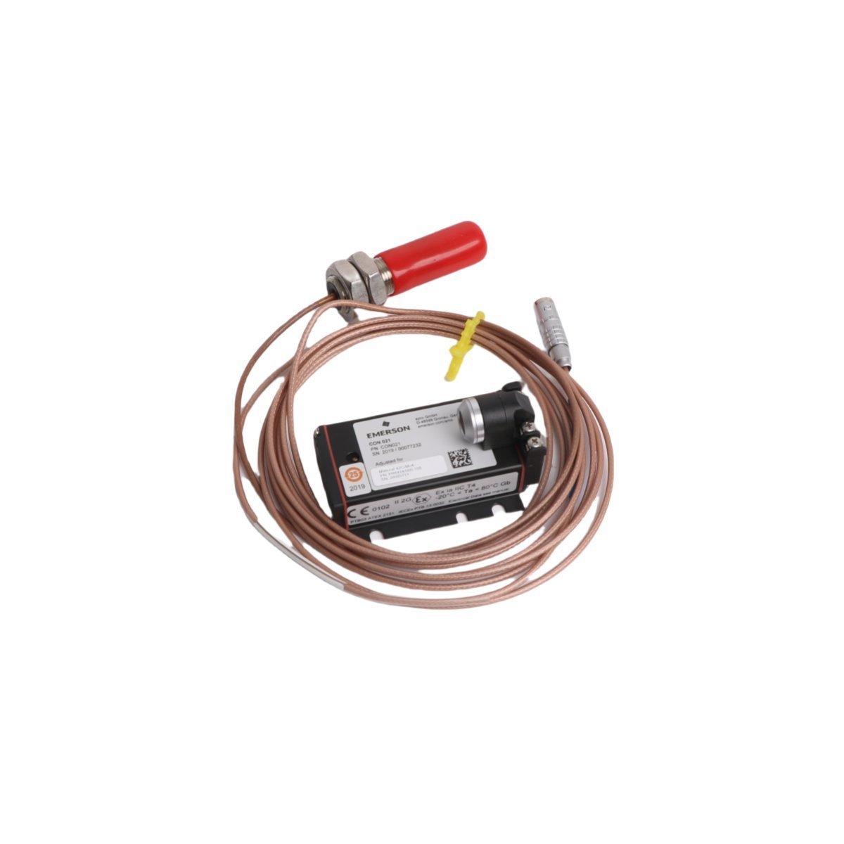
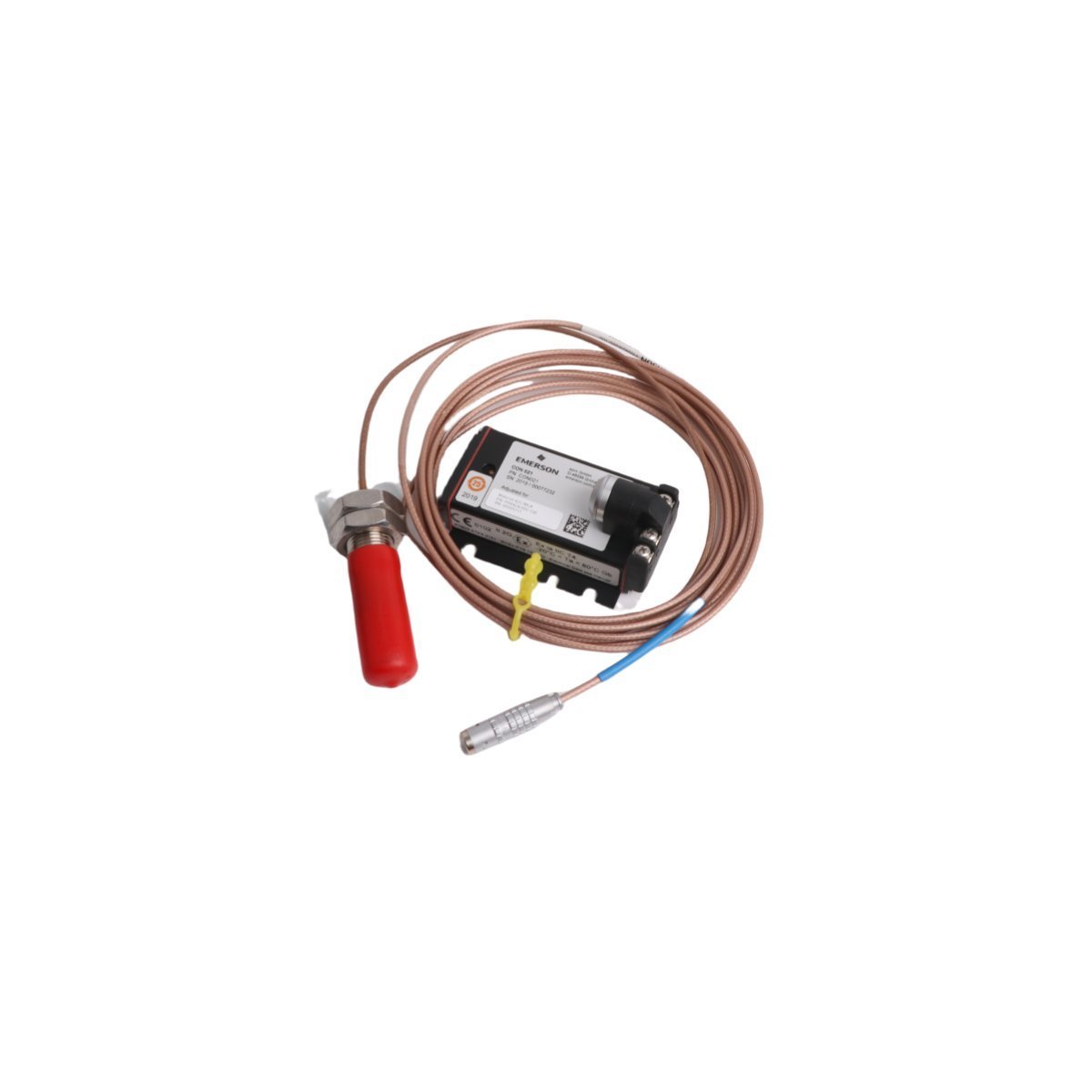
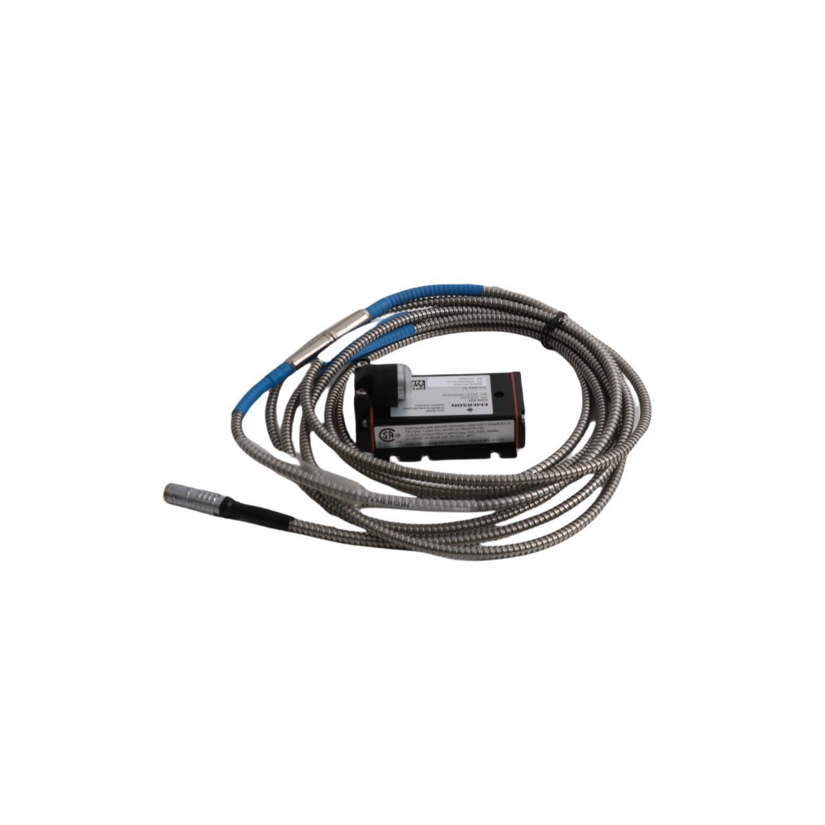
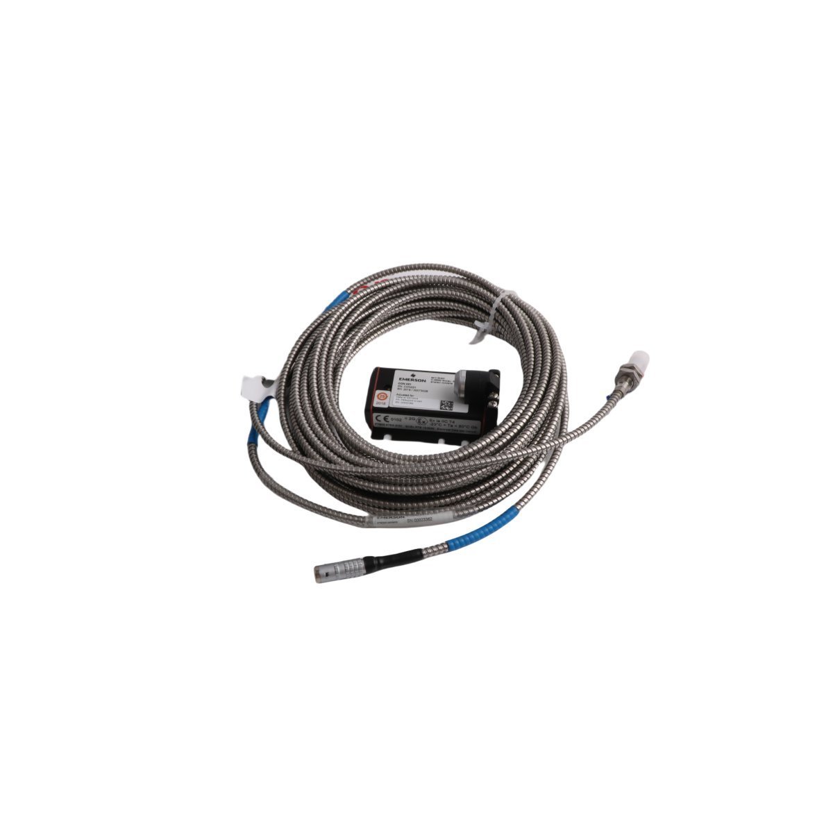
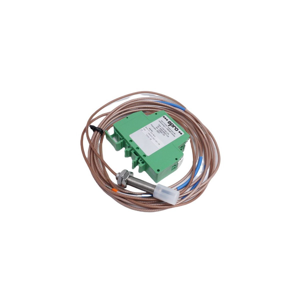
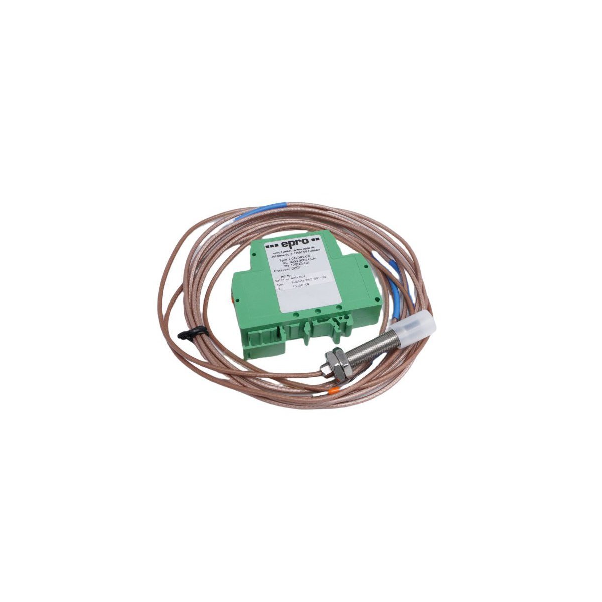
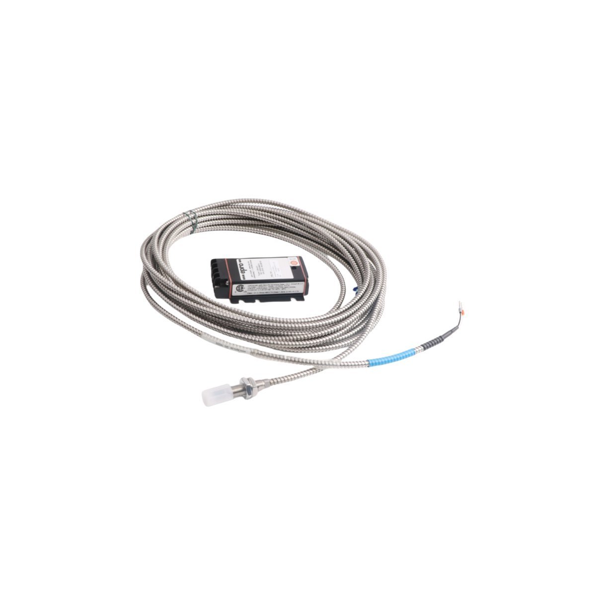
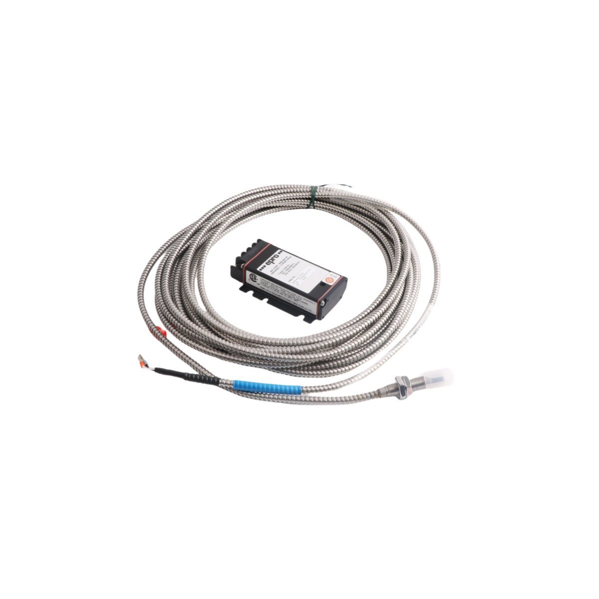
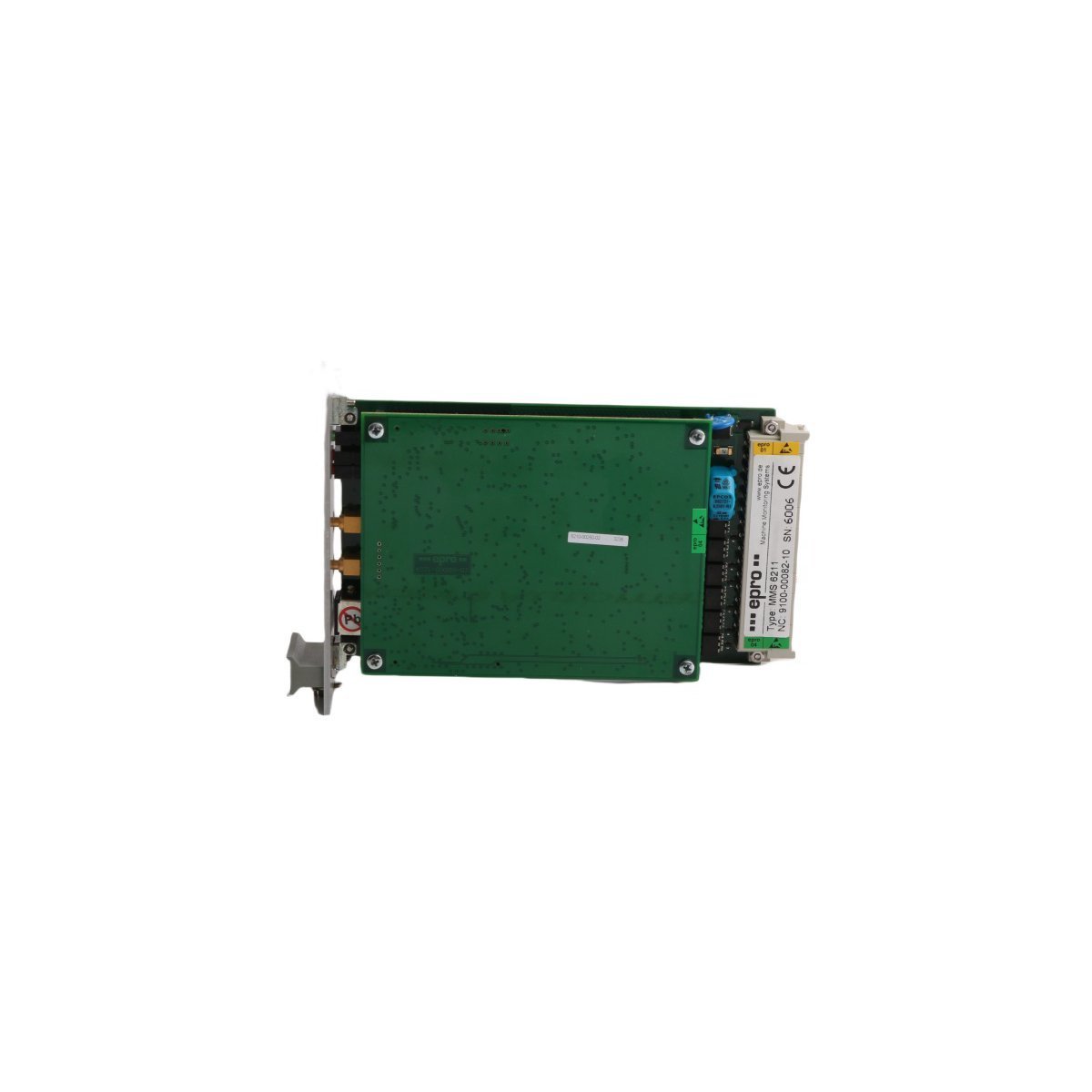
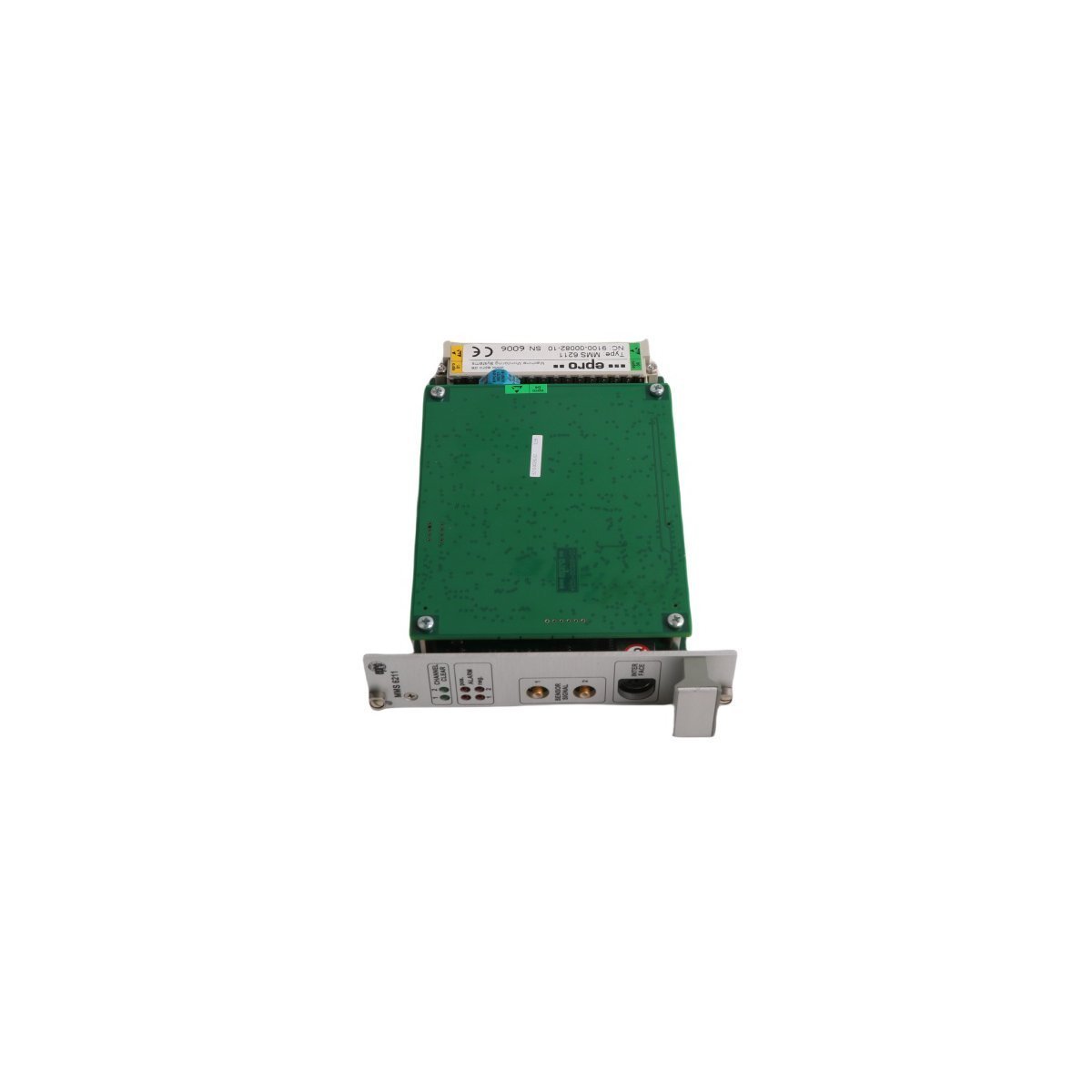
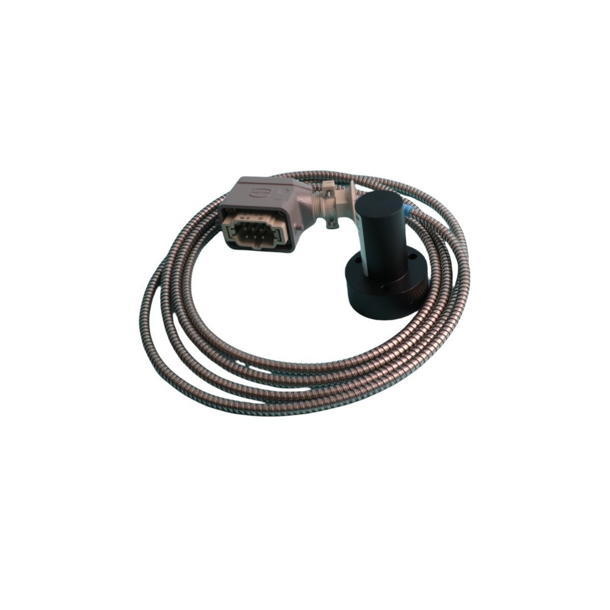
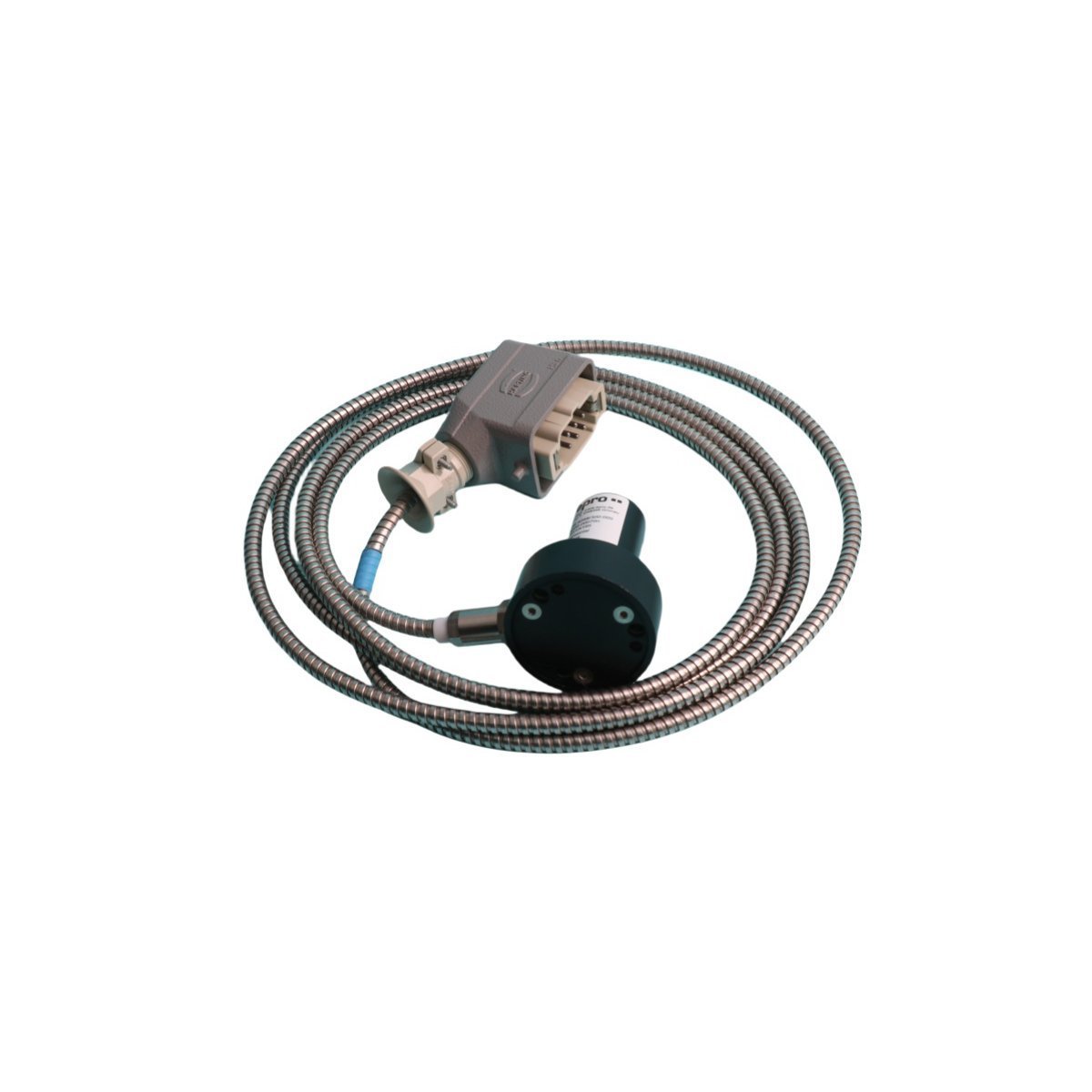
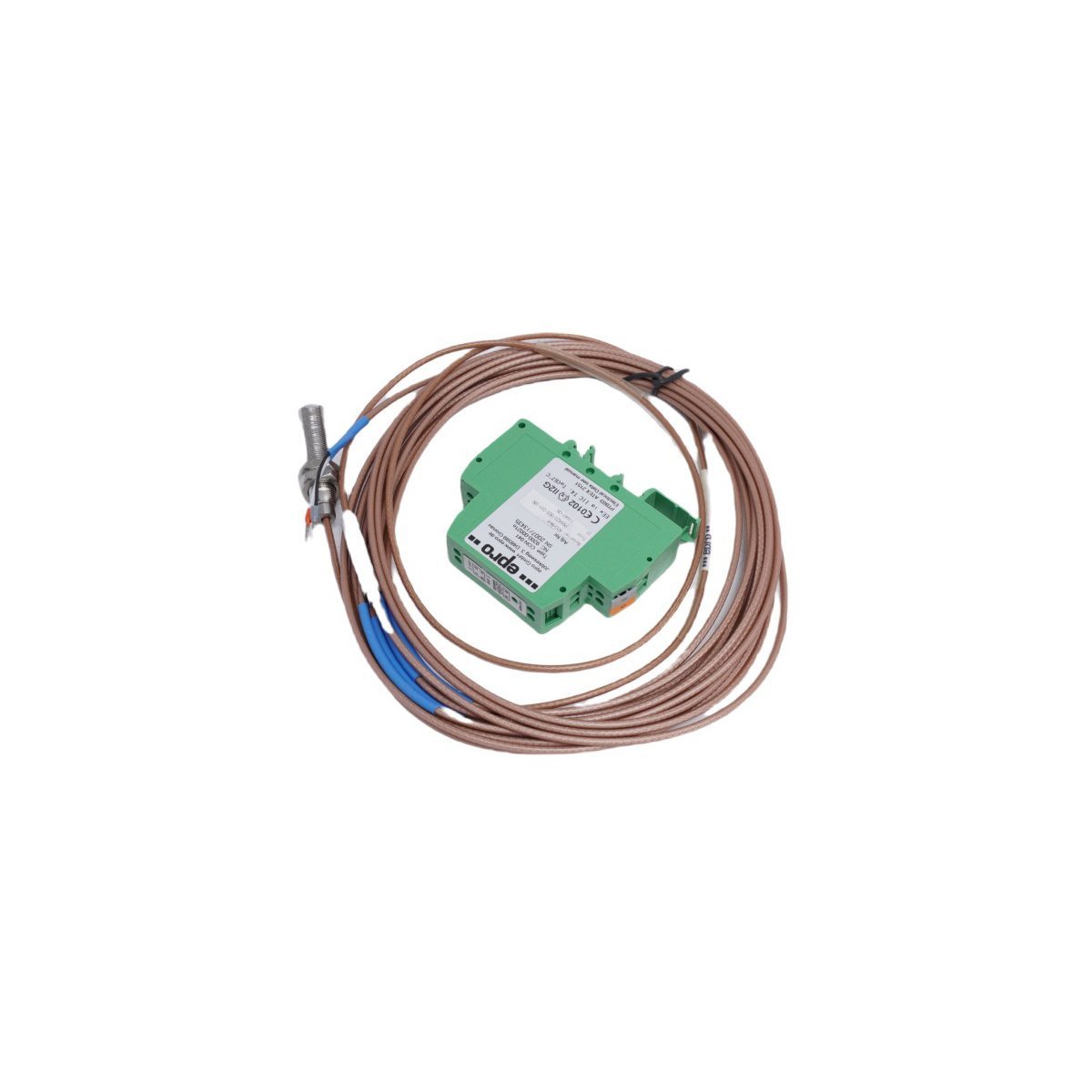
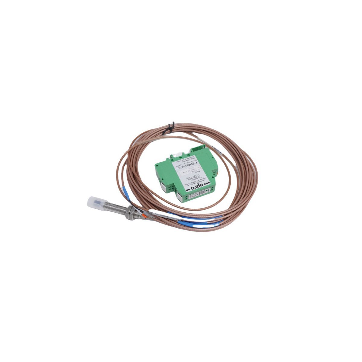
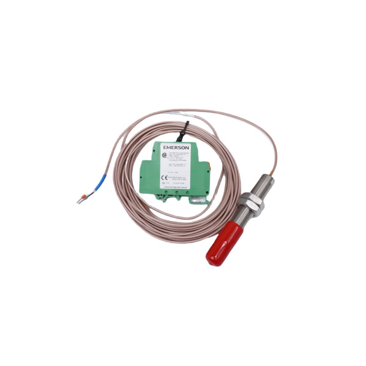
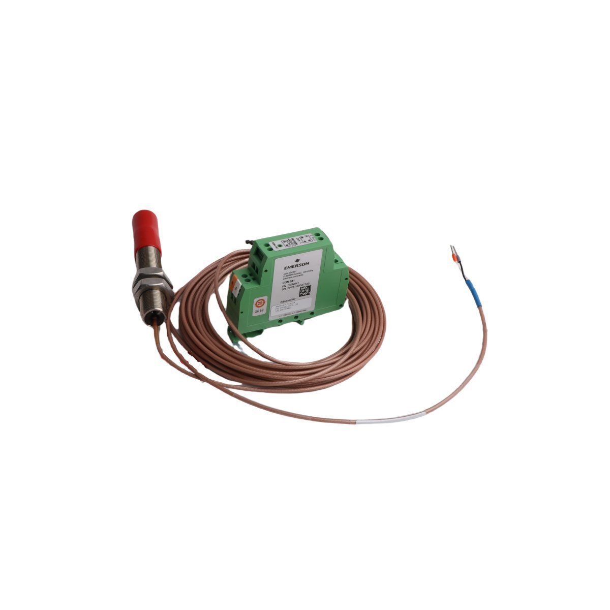
Emerson PR6423/01R-040 CON021 Eddy Current Sensor
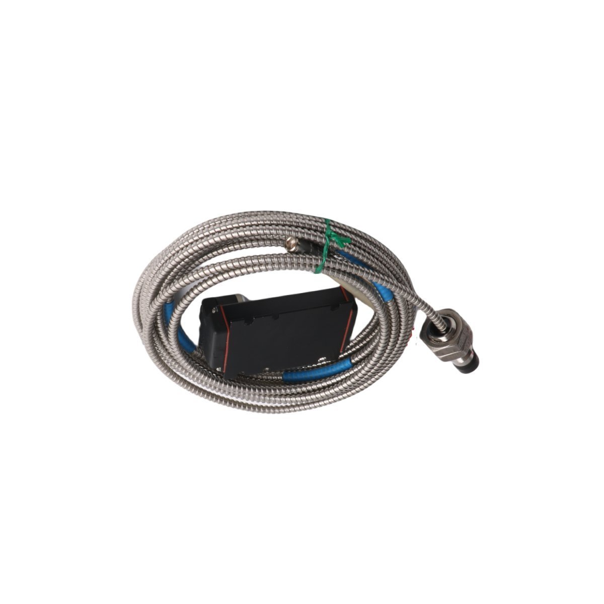
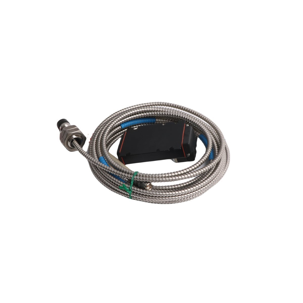
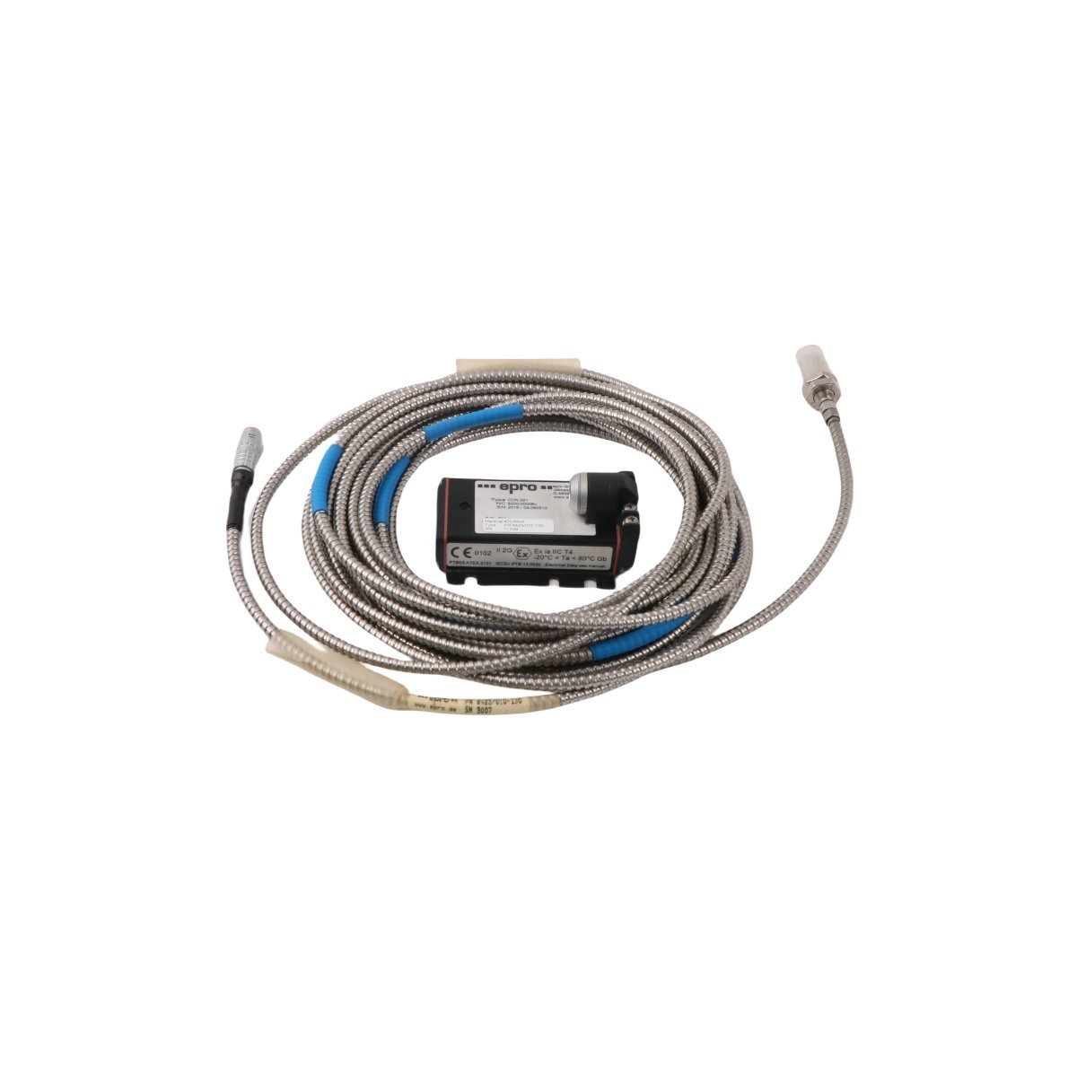
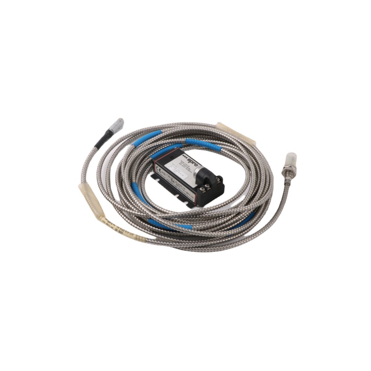
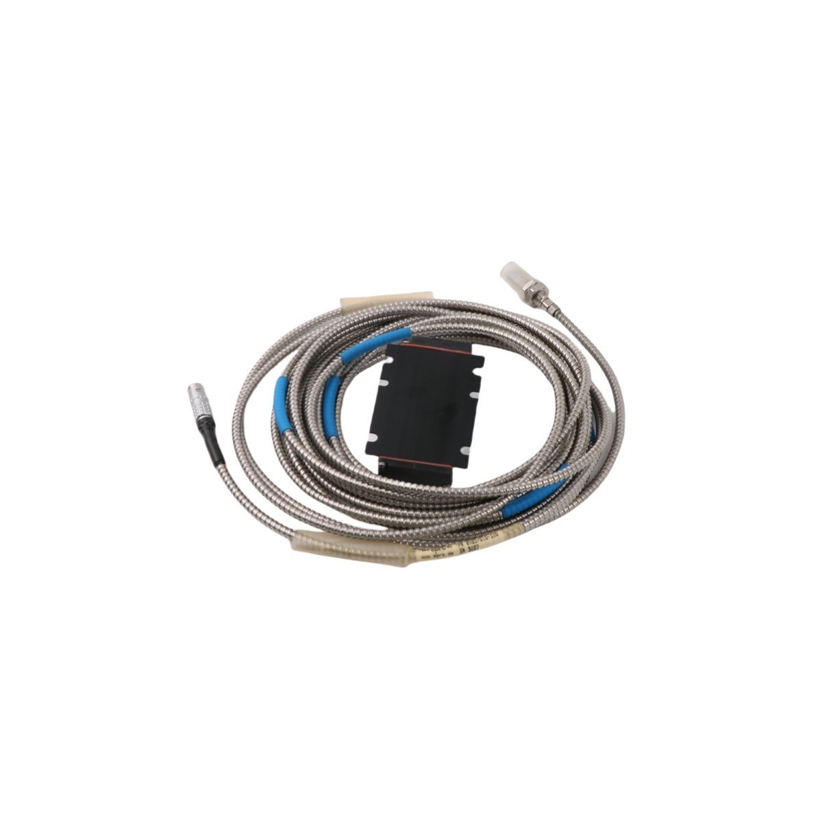
Configured for non-contact shaft vibration and axial displacement measurement in EPRO machinery monitoring systems, the Emerson PR6423/01R-040 CON021 (PR6423/01R-040 Eddy Current Sensor) provides direct physical signal conditioning for rotating element health monitoring.
Hardware Specifications
| Parameter | Specification |
|---|---|
| Model | PR6423/01R-040 CON021 |
| Brand | Emerson |
| Product Range | EPRO |
| Module Type | Eddy Current Sensor |
| Origin | USA |
| Weight | 0.28 kg |
| Dimensions | 20 x 20 x 4 cm |
| Operating Temp | -35 to 180 deg C |
| Power Consumption | Passive sensor coil (driven by signal converter) |
| HS Code | 8537101190 |
| Lifecycle Status | Discontinued (Dec 31, 2018) |
Process Control and DCS Characteristics
- Converts magnetic field impedance changes into high-frequency voltage proportional to metallic target distance.
- Integrates with 4-20 mA HART loop protocol transmitters and DCS analog channels for signal transmission.
- Provides channel-to-channel isolation to prevent loop interference across adjacent turbomachinery measurement channels.
- Maintains measurement accuracy during temperature variations using cold junction compensation (CJC) circuits in the matching CON021 signal conditioning unit.
Frequently Asked Questions
Q: How does the CON021 signal converter interact with the PR6423/01R-040 probe?A: The CON021 converter supplies the high-frequency excitation voltage to the probe tip coil and converts raw impedance variations into standardized proportional voltage signals.Q: What mounting precautions prevent signal distortion on this eddy current probe?A: Maintain a clear unthreaded side clearance area around the probe tip to prevent adjacent structural metals from skewing the calibrated inductance field.Field Installation Guidelines
- Verify mechanical clearance between the probe tip and target shaft face prior to power up to prevent physical impact damage.
- Run coaxial interconnect cabling through grounded steel conduit to isolate signal lines from high-voltage motor conductors.
- Observe a minimum 30 mm cable bend radius during routing to protect internal conductor shielding.