Secure your HONEYWELL MLI-DN32UA Base Module today. Brand New, Original Stock, and ready for Global Shipping. Perfect for expanding your DCS system capacities. Contact us now to finalize your order.
The HONEYWELL MLI-DN32UA, also cataloged as the MLI-DN32UA Base Module, operates as a dedicated hardware component for direct process execution and signal conversion within DCS platforms. It integrates digital processing, analog measurement interfaces, and dedicated communications routing to manage physical field instrumentation loops directly.
Hardware Specifications
Parameter
Specification
Model
MLI-DN32UA
Brand
HONEYWELL
Origin
USA
Weight
0.4 kg
Dimensions
7 x 14 x 14.5 cm
Operating Temp
0 to 60 deg C
Power Consumption
AC 100-240 VAC Input
Digital Inputs
16 Channels
Digital Outputs
16 Channels (Sink Type)
Analog Channels
8 Channels Total (Configurable I/O)
Analog Signal Ranges
1-5 V, 0-5 V, 0-10 V, -10 to 10 V, 4-20 mA, 0-20 mA
Communication Interfaces
FENET (Ethernet router), 2SNET
HS Code
8537101190
Process Control & DCS Instrumentation
The HONEYWELL MLI-DN32UA incorporates precise analog processing circuit matrices supporting 4-20 mA HART loop protocol parameters and discrete analog signaling environments. The multi-range internal configuration provides cold junction compensation (CJC) capabilities natively when processing matched external sensors. High channel-to-channel isolation safeguards system-side logic blocks from external electrical transients and field-side ground loops. The network layer routes internal bus data packets into deterministically managed Ethernet segments via built-in routing services, preserving signal coherence across large-scale process automation systems.
Frequently Asked Questions
Q: What are the primary configuration options for the 8 analog channels on the MLI-DN32UA?
A: The analog block is split into configurable input/output matrices. Each individual path allows independent jumper or software selection to interface with standard 4-20 mA loop networks or variable voltage signals ranging from -10 VDC to +10 VDC.
Q: How is the system grounded to ensure channel-to-channel isolation integrity?
A: Field wiring blocks utilize optical and galvanic separation barriers between the field terminal block and the inner logic backplane. Shielded twisted pairs must terminate directly at the field grounding busbar to prevent electrical interference from disturbing the low-voltage processing circuitry.
Field Installation Guidelines
Mounting Alignment: Affix the module firmly to a grounded industrial DIN rail inside a protective, climate-controlled enclosure. Maintain a minimum clear boundary space of 50 mm above and below the module housing to facilitate standard thermal convection and heat dissipation.
Electrical Safety and Wiring: Prior to inserting or routing any interface connections, disconnect the main AC supply lines (100-240 VAC). Run low-voltage analog signal cables separate from high-current AC power cables in separate wire ducts to eliminate cross-talk or inductive coupling risks.
Shield Grounding Matrix: All 4-20 mA signal shield wires must terminate at a single external reference ground plate. Do not ground the cable shield at both ends, as this generates local ground loops that degrade measurement fidelity.
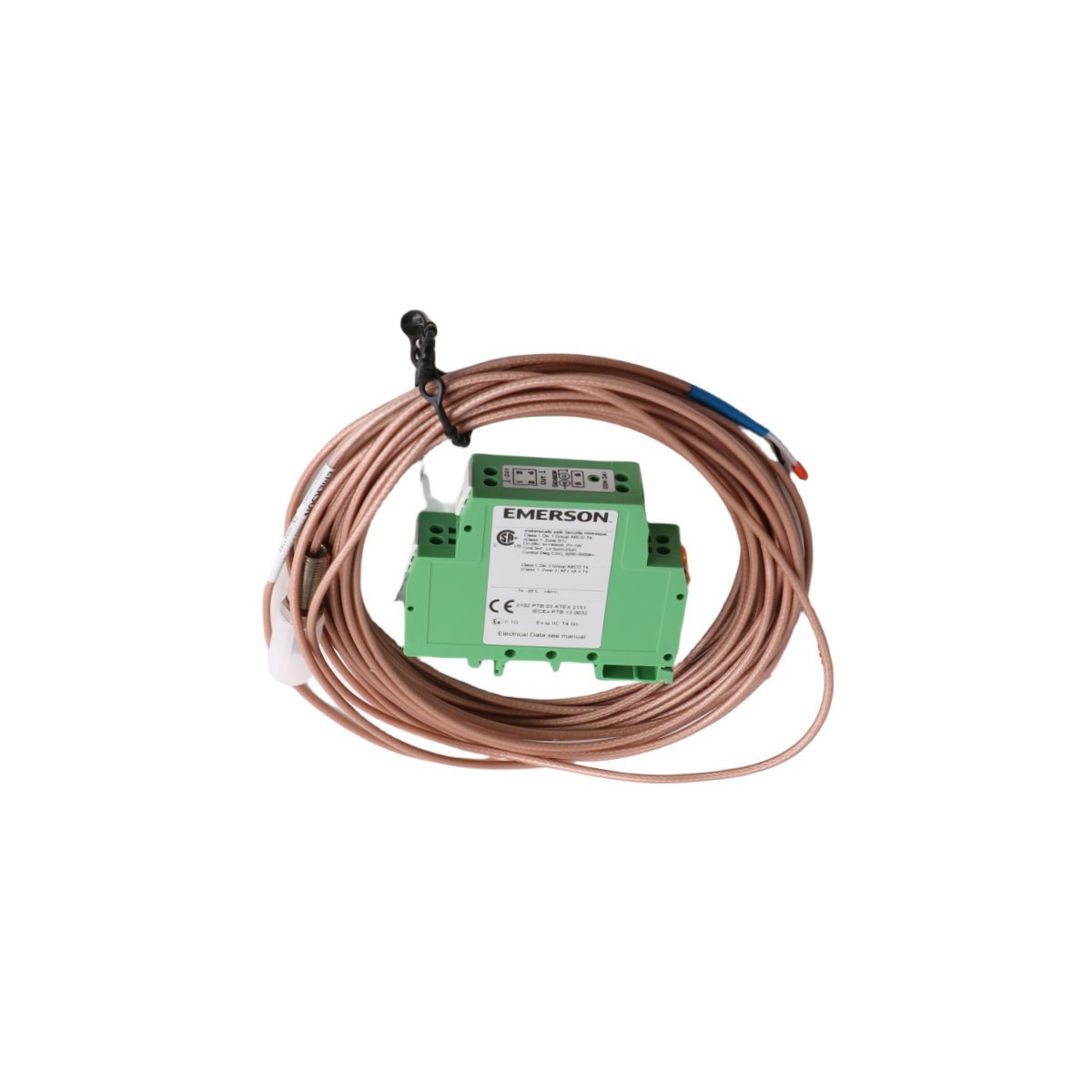
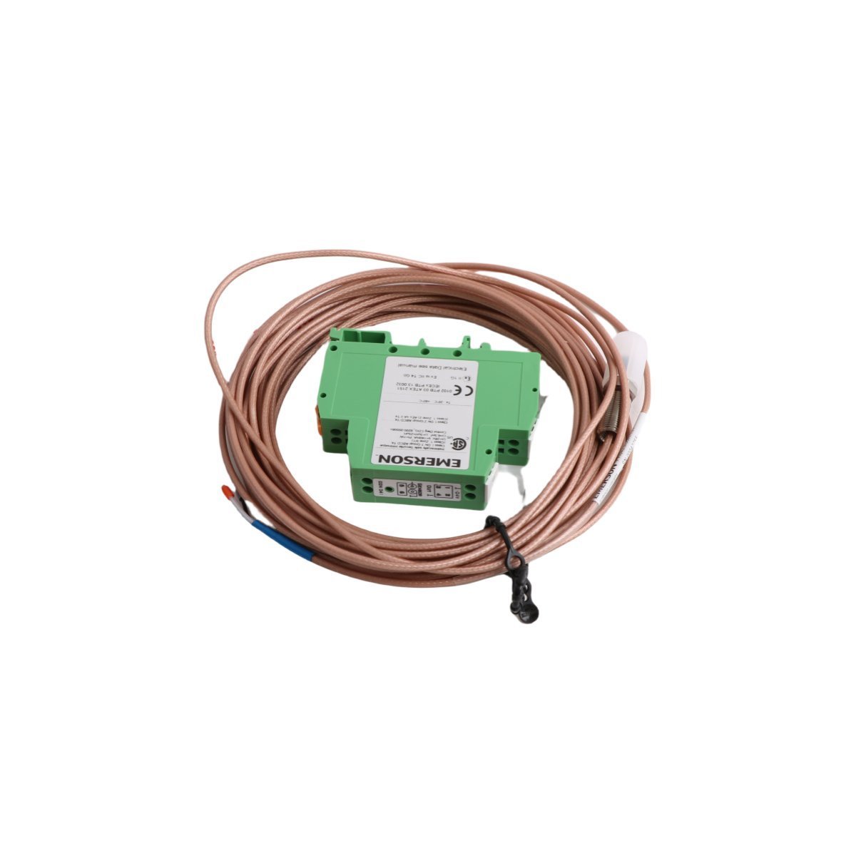
The EMERSON PR6423/00R-131 CON041 is a factory-original eddy current signal converter designed for high-accuracy displacement monitoring. Acquire this brand new, original stock component with secure worldwide shipping options and guaranteed hardware verification. Contact our technical team today to finalize your industrial replacement requirements.
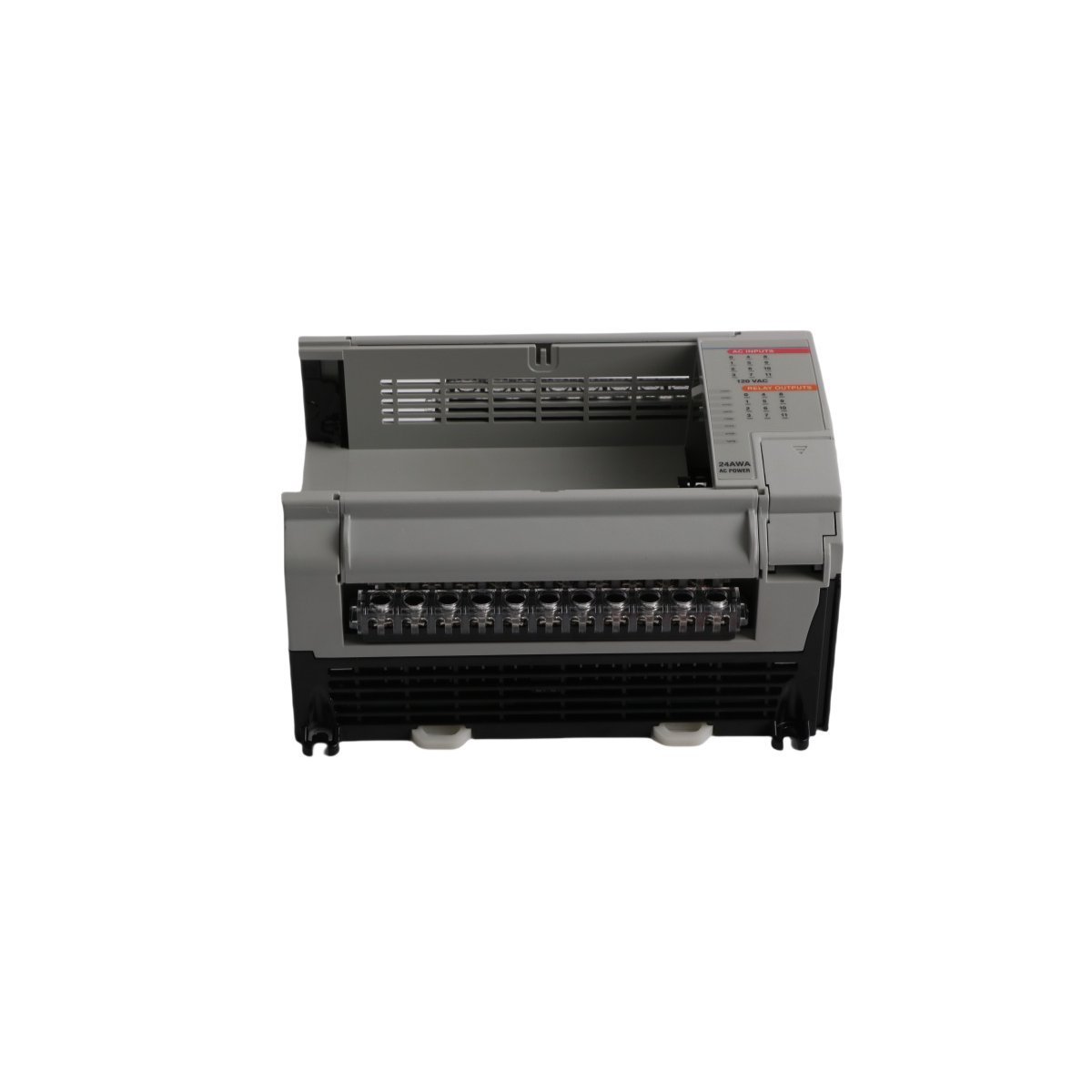
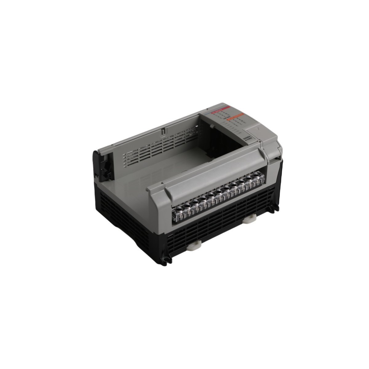
The Allen-Bradley 1764-24AWA is a 120 VAC powered MicroLogix 1500 PLC base unit featuring 12 embedded AC inputs and 12 relay outputs. Brand new factory-sealed units are ready for industrial machinery deployments with fast worldwide shipping. Keep your legacy control panels running efficiently.
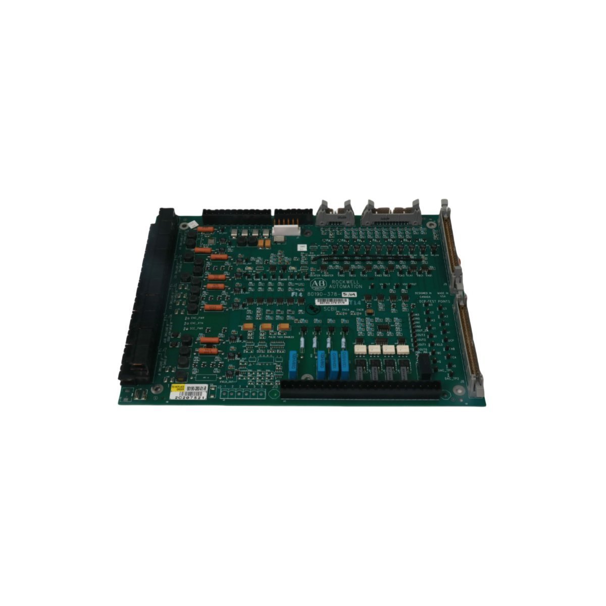
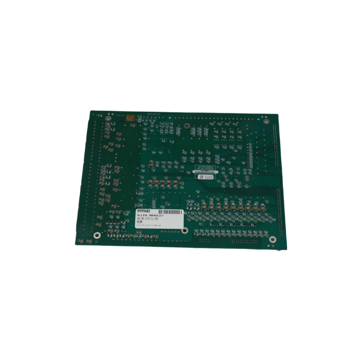
The Allen-Bradley 80190-380-01-R is a PLC-5 system analog control board module for precision manufacturing automation. Brand New and Original Stock available for Global Shipping.
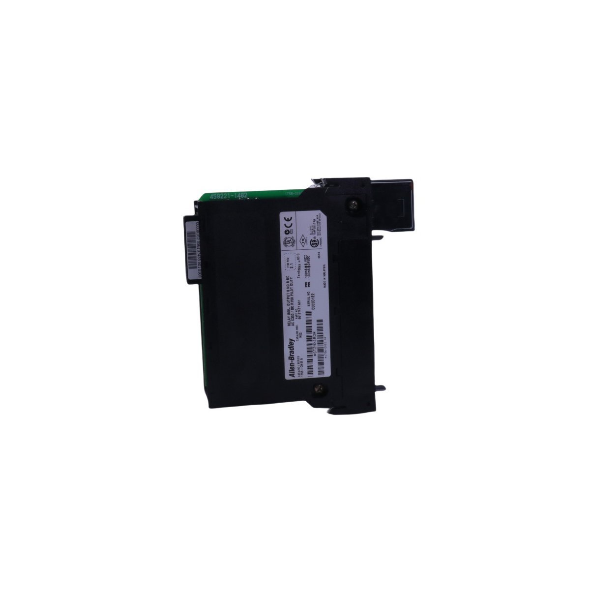
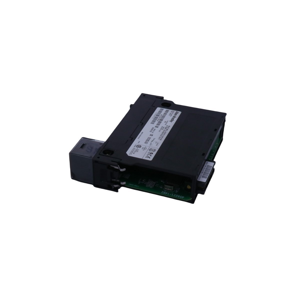
The Allen Bradley 1756-OX8I is an 8-channel isolated relay output module for ControlLogix assemblies. This brand new component is original stock and ready for global shipping.
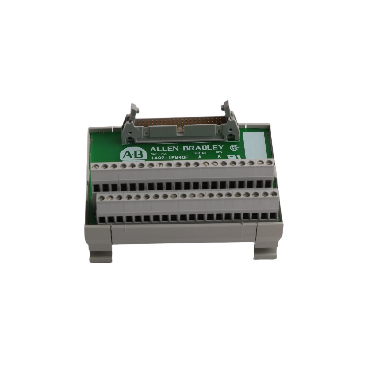
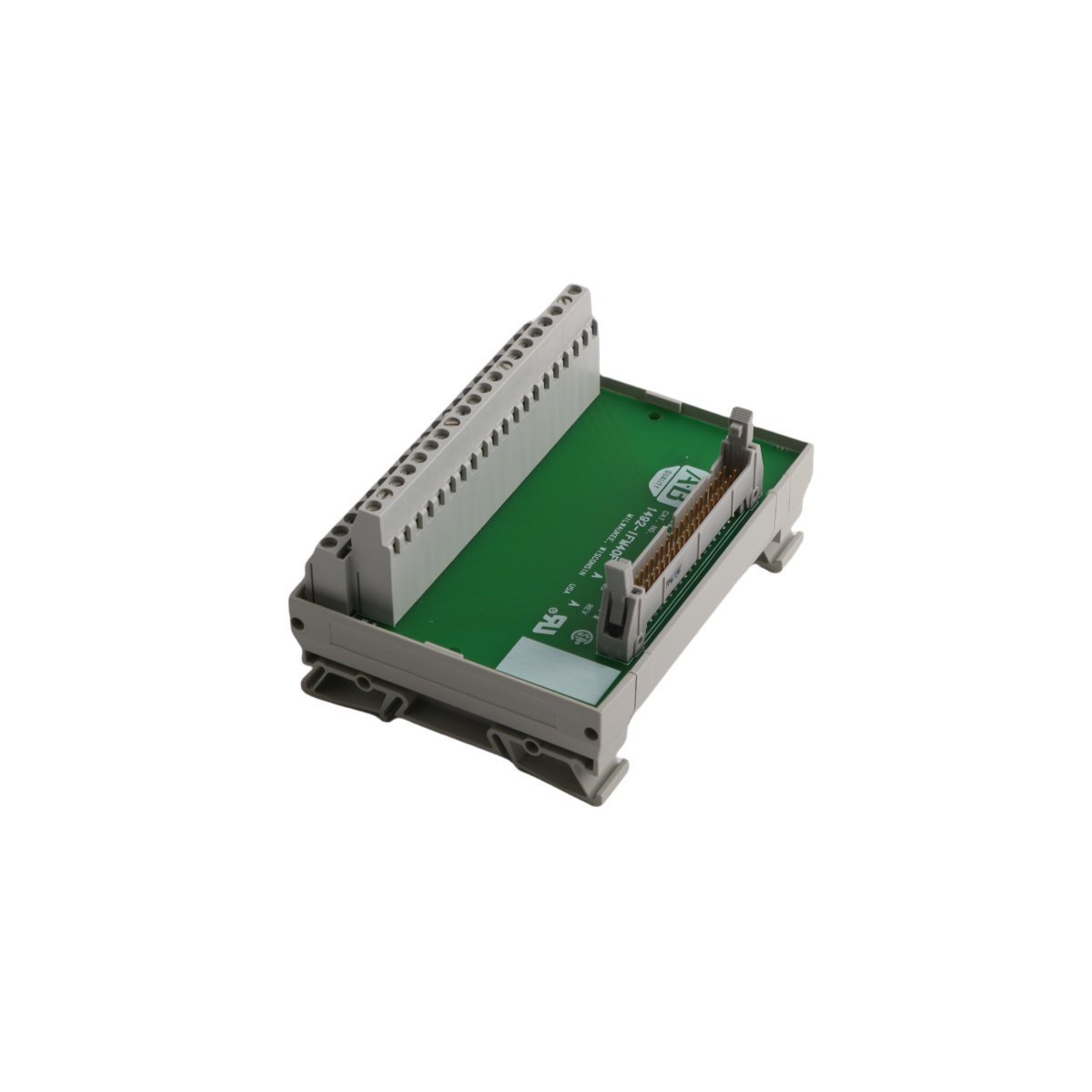
he Allen Bradley 1492-IFM40F-FS-2 is a 40-contact fusible wiring systems interface module. This brand new, original stock component is available for global shipping to support your programmable logic controller architecture.
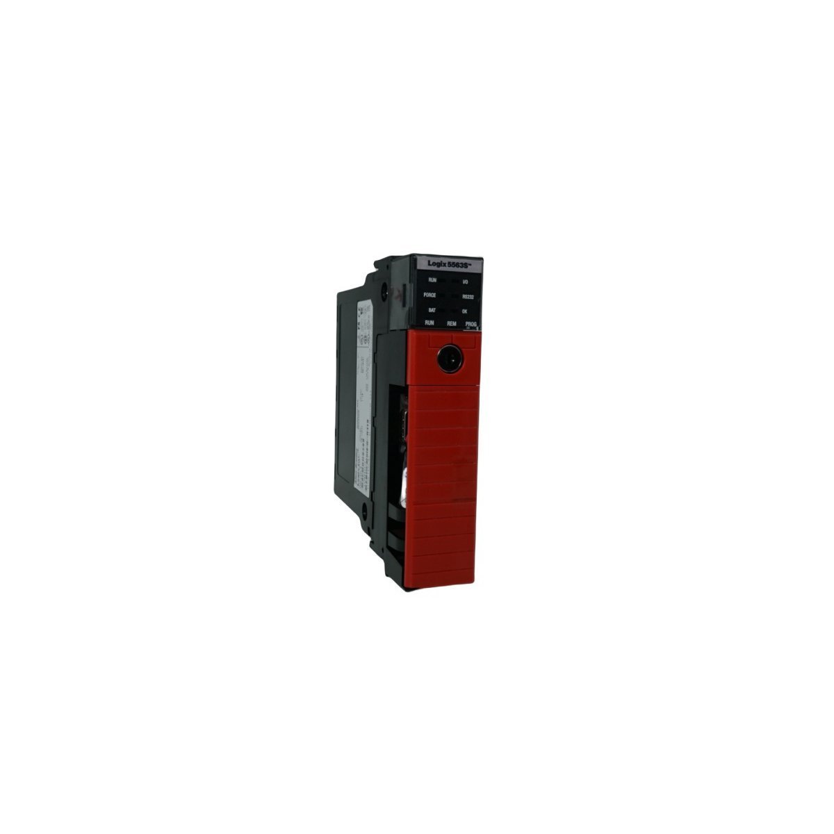
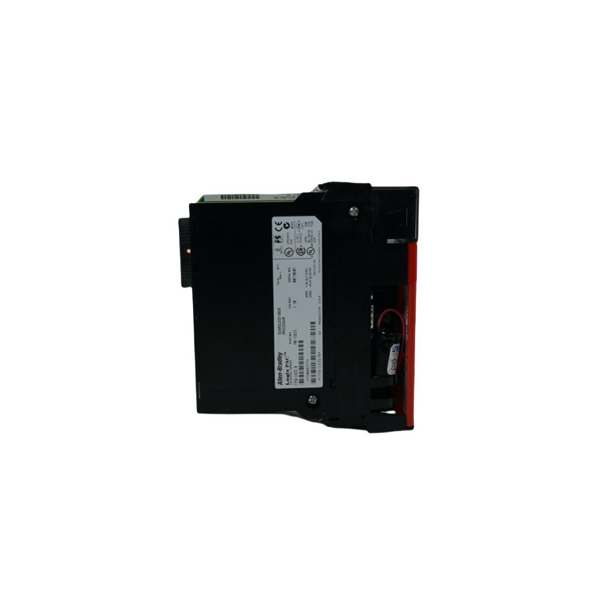
The Allen-Bradley 1756-L63S is a ControlLogix GuardLogix safety controller featuring 8MB user memory. Brand New, Original Stock, available now for global distribution.
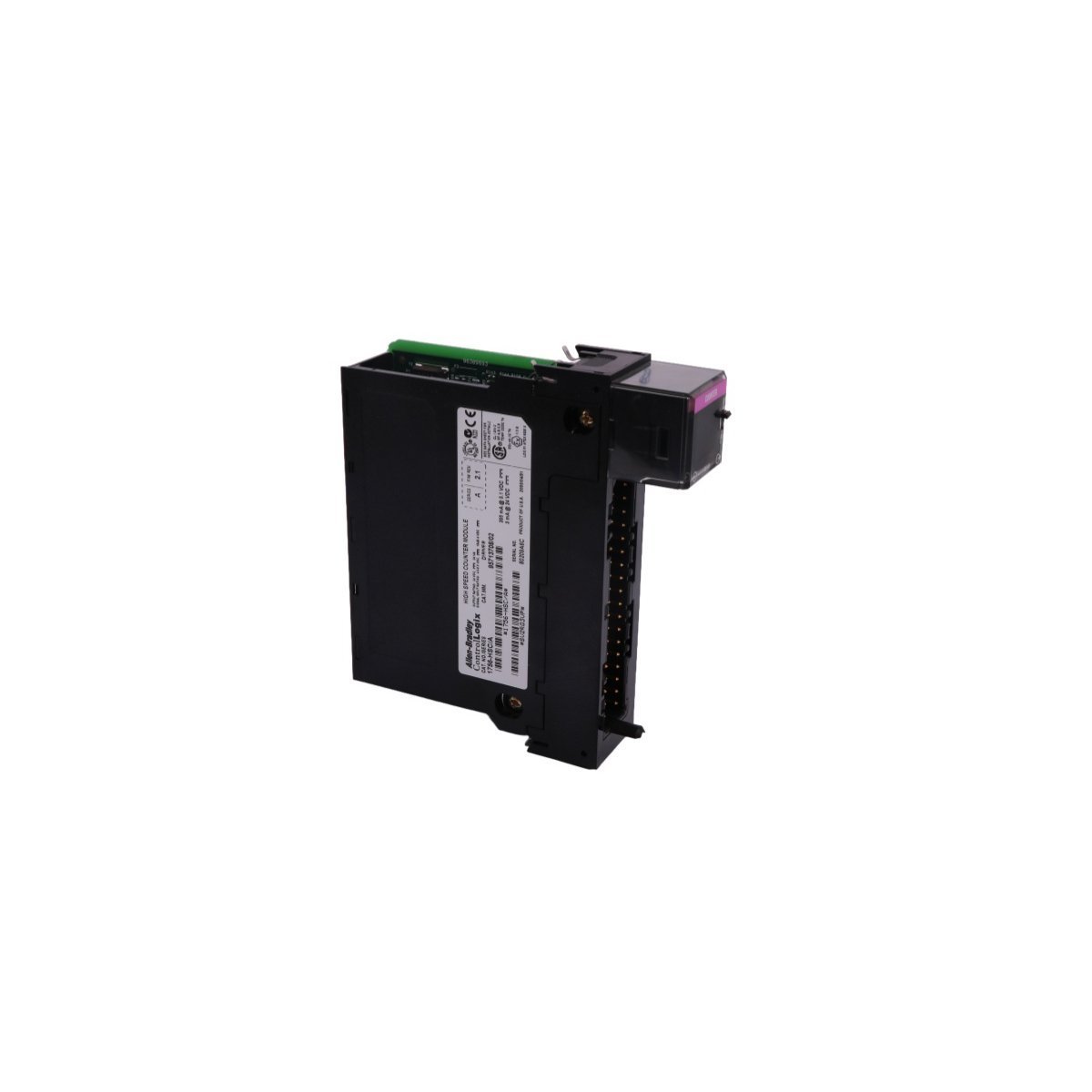
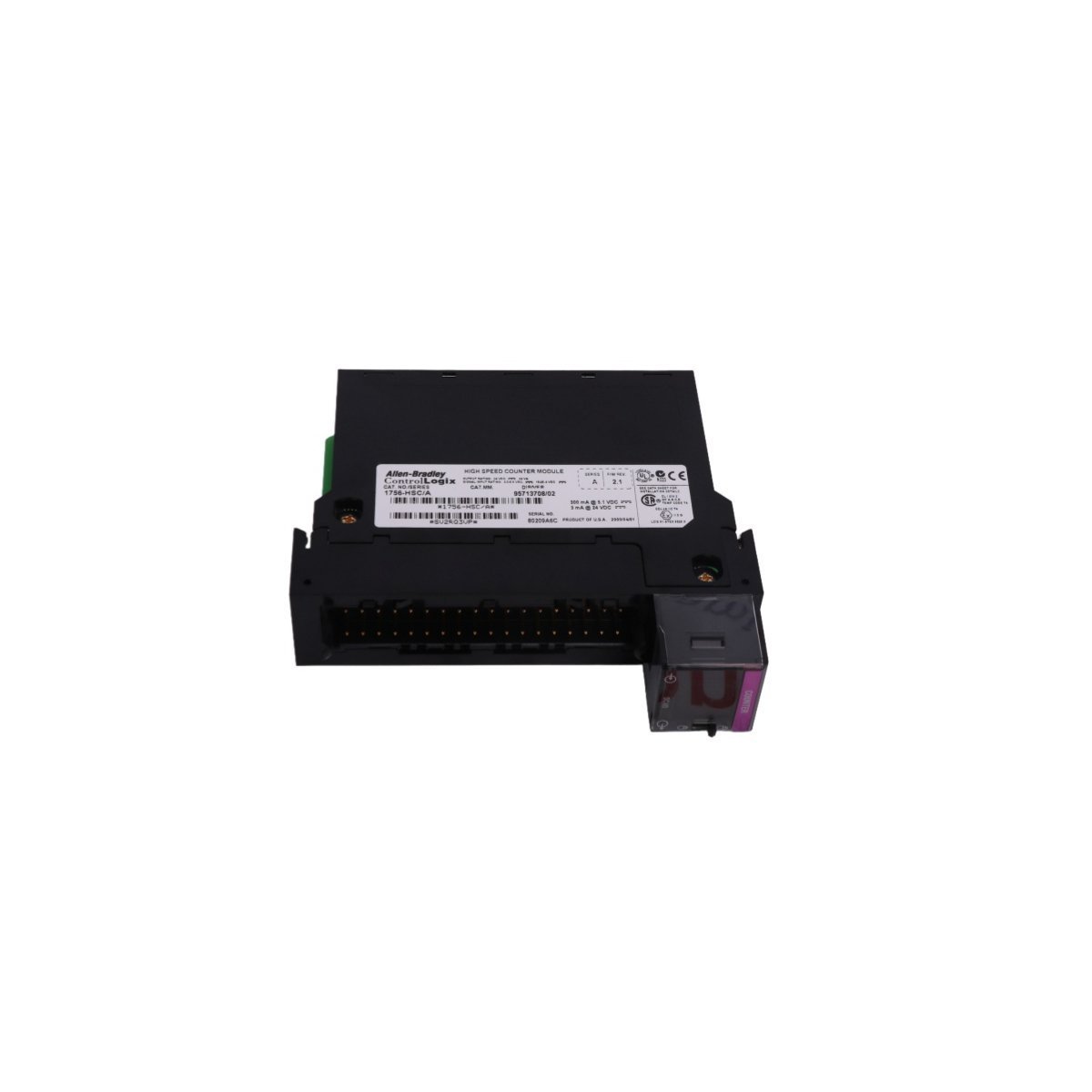
The Allen-Bradley 1756-HSC is a high-speed counter module for the ControlLogix platform, designed to provide accurate signal tracking and reliable pulse input processing.
The ABB PM864AK01 (3BSE018161R1) is a high-speed MPC862 processor unit designed for AC 800M and 800xA control systems.It features 32MB RAM, dual Ethernet ports, and supports up to 96 I/O modules, providing reliable real-time execution for demanding industrial automation tasks
We are committed to protecting your privacy. The information collected here is strictly used to provide the requested quotes, technical support, and relevant industrial automation solutions.