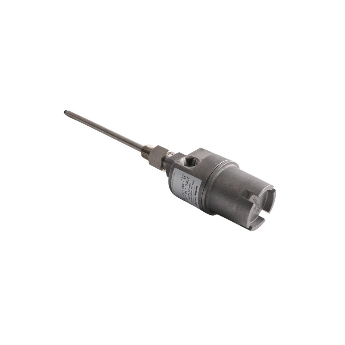
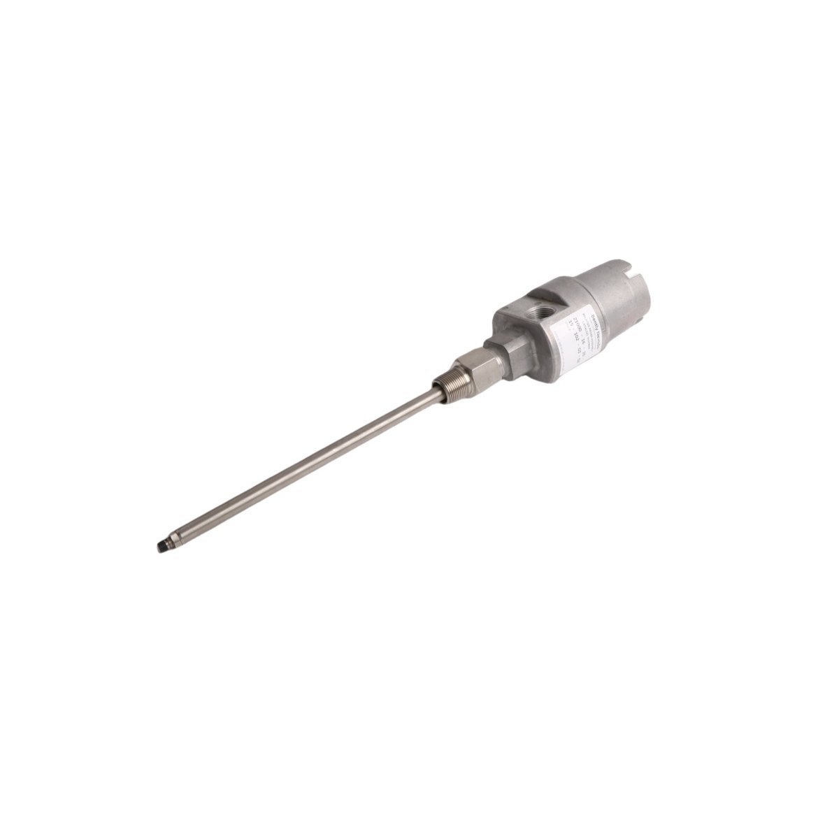
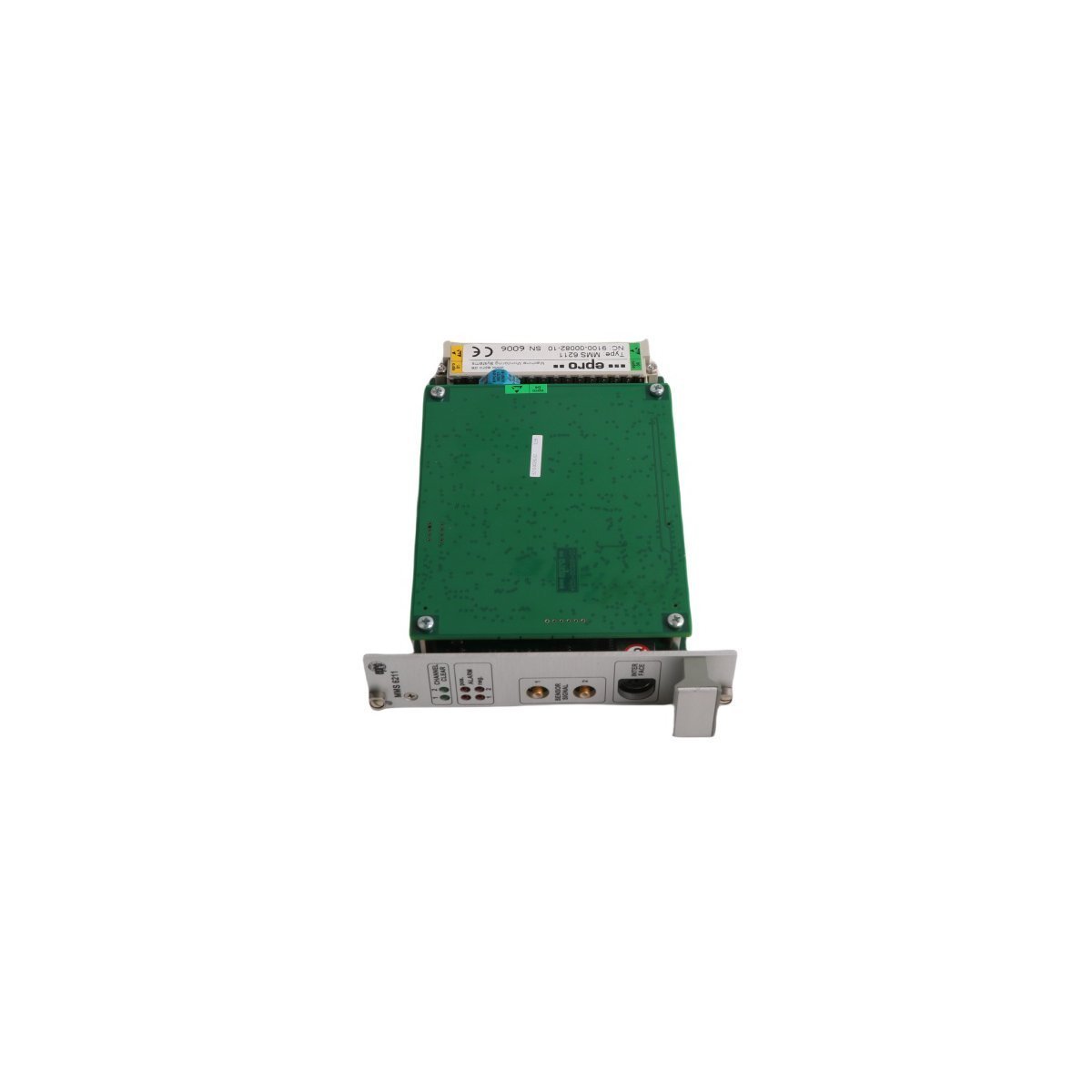
You are here:
SKU: 31000-28-05-15-026-06-02

Bently Nevada 31000-28-05-15-026-06-02 Proximity Probe Housing Assemblies

Buy the Bently Nevada 31000-28-05-15-026-06-02 Proximity Probe Housing assembly. This product is available as Brand New, Original Stock with Global Shipping. Secure your critical TSI components and request a quote today.

Configured for mechanical monitoring protection in TSI (Turbine Supervisory Instrumentation) networks, the Bently Nevada 31000-28-05-15-026-06-02, also cataloged as the 31000 Proximity Probe Housing Assemblies, provides direct physical/electrical execution. This assembly houses proximity probes to monitor radial vibration, axial thrust, or shaft position relative to rotating machinery elements.

Hardware Specifications

ParameterSpecification
Model31000-28-05-15-026-06-02
BrandBently Nevada
OriginUSA
Weight1.2 kg
Dimensions30.02 x 12.00 x 9.14 cm
Operating Temp-35 to +120 deg C (Standard industrial rating)
Power ConsumptionPassive mechanical containment (Probe dependent)
System Compatibility3300 Proximity Transducer System
Module TypeProximity Probe Housing Assemblies
ApplicationTSI Mechanical Monitoring

Eddy-Current Probe Scaling and Gap Voltage Validation

The housing assembly maintains spatial alignment required for eddy-current probe scaling across the target measurement range. Proper installation ensures the probe remains perpendicular to the observed shaft surface, preventing cross-talk suppression failures and signal distortion. During deployment, technicians must perform a gap voltage validation target checklist, adjusting the probe position within the housing until the proximitor output registers the standard -10 VDC baseline bias. This physical positioning establishes the linear midpoint necessary for accurate tracking of rotor dynamics.

Frequently Asked Questions

Q: Does this housing assembly contain active electronic components or require a direct power input?

A: No, the housing is a passive mechanical containment device designed to position and isolate proximity probes. Electrical characteristics, including current draw and voltage constraints, are governed by the installed 3300 series probe and proximitor sensor.

Q: How is cross-talk suppression managed inside this housing configuration?

A: Suppression of signal interference is managed through controlled spacing and structural isolation. To maintain proper eddy-current probe scaling, ensure that the proximity sensor probe tips are separated from adjacent conductive housing walls according to minimum unthreaded clearance mandates.


Field Installation Guidelines

  • Verify that the external sleeve or casing thread engagement conforms to standard NPT dimensions, requiring a minimum 5-thread mechanical engagement for optimal environmental sealing.
  • Run probe extension cables through flexible or rigid conduit to shield raw transducer signals from electromagnetic fields and mechanical abrasion.
  • Adjust internal positioning sleeves incrementally during the gap voltage validation phase until the multimeter indicates -10 VDC across the signal and common terminals.
  • Connect the outer shield of the transducer cable directly to the designated instrument ground at the housing interface or junction box to maintain shielding continuity.