Sale!
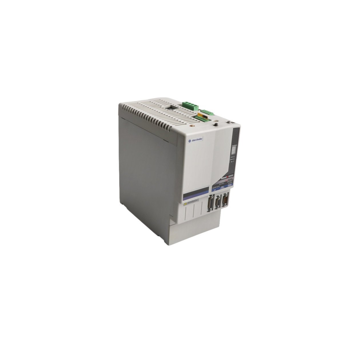
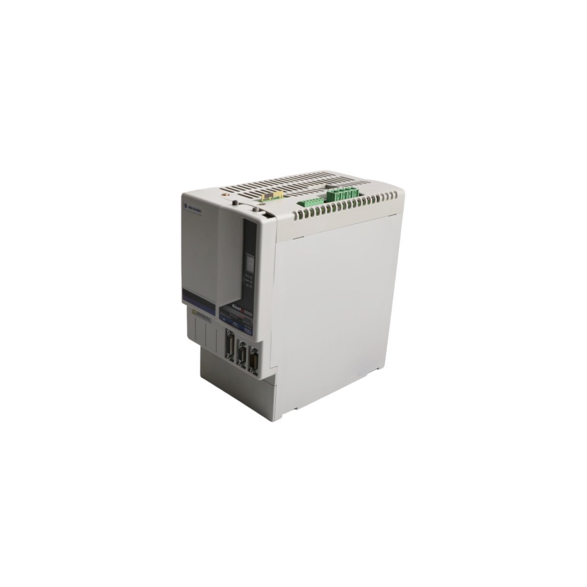
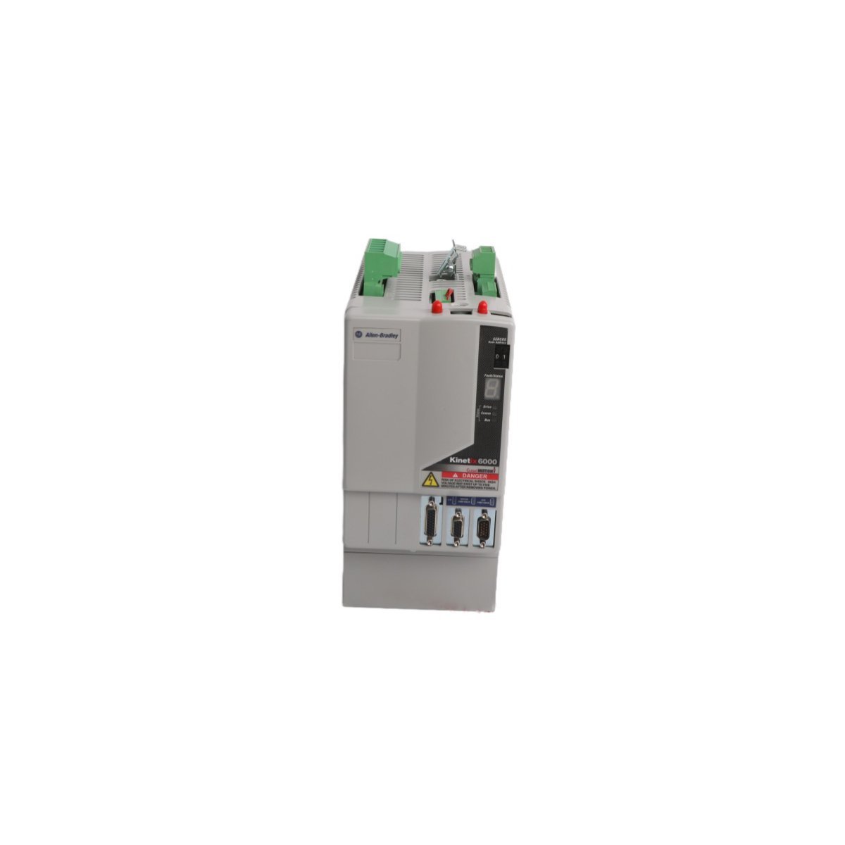
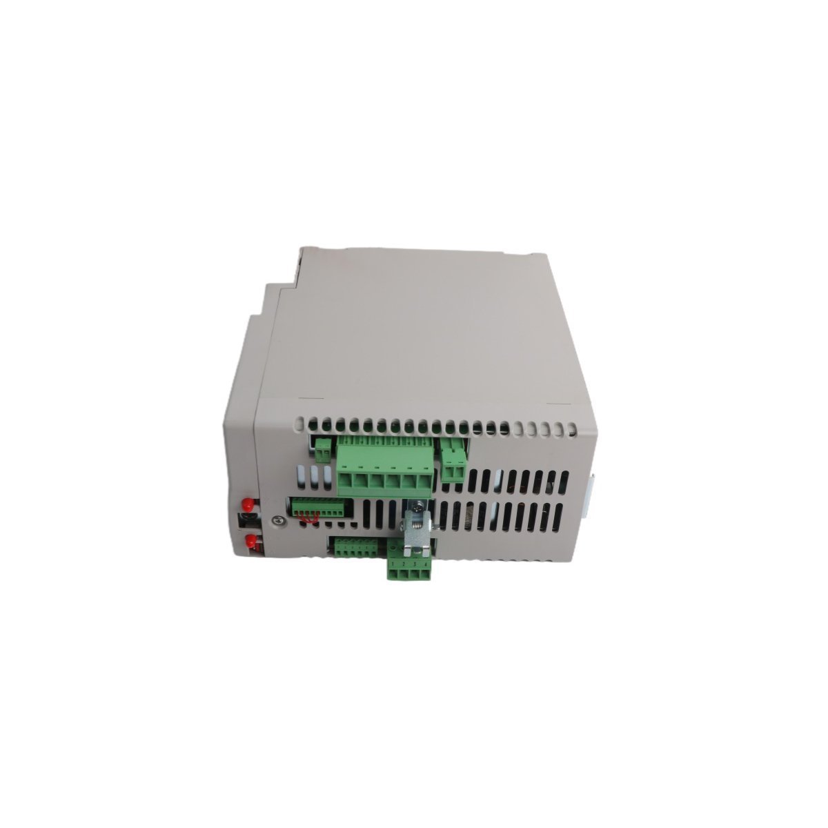
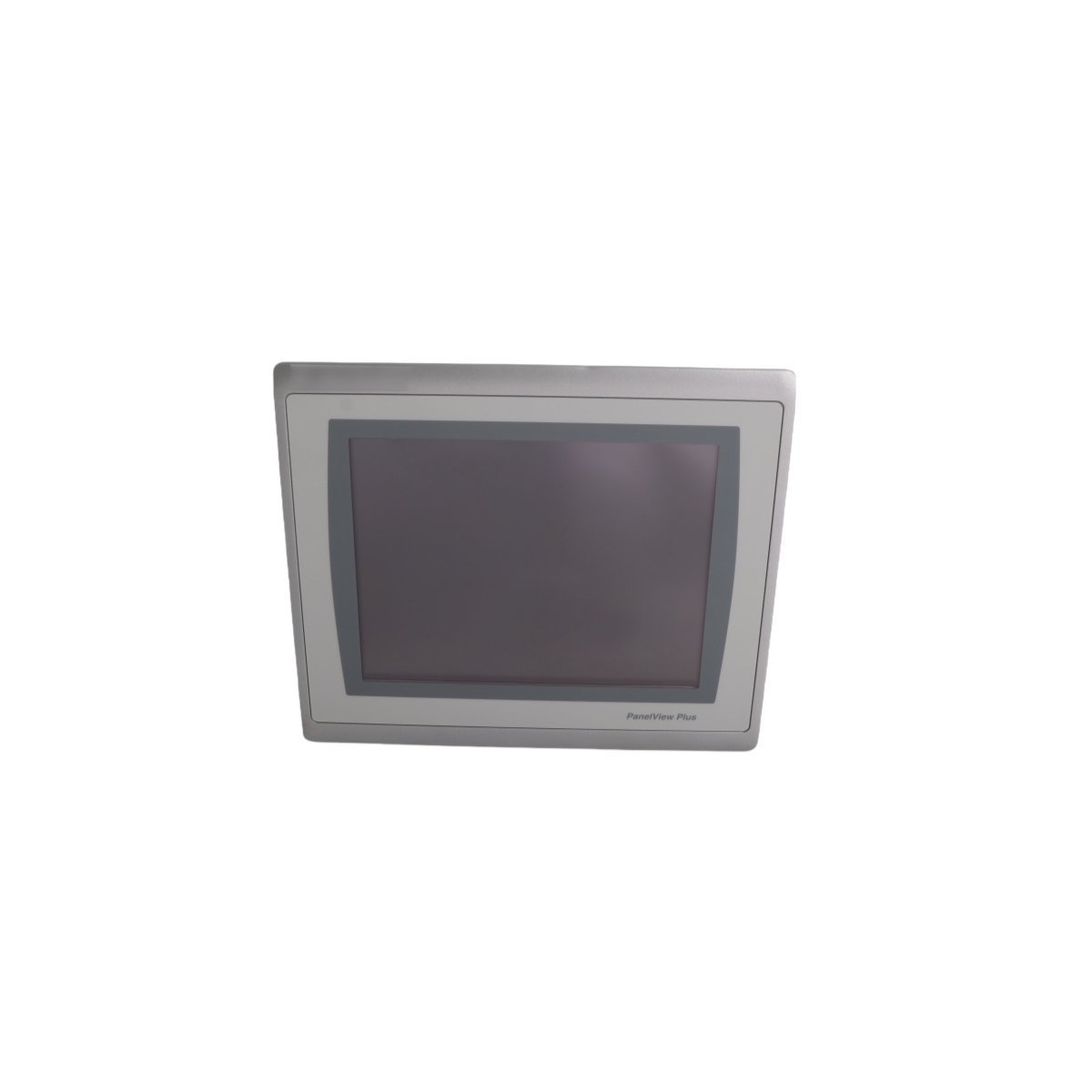
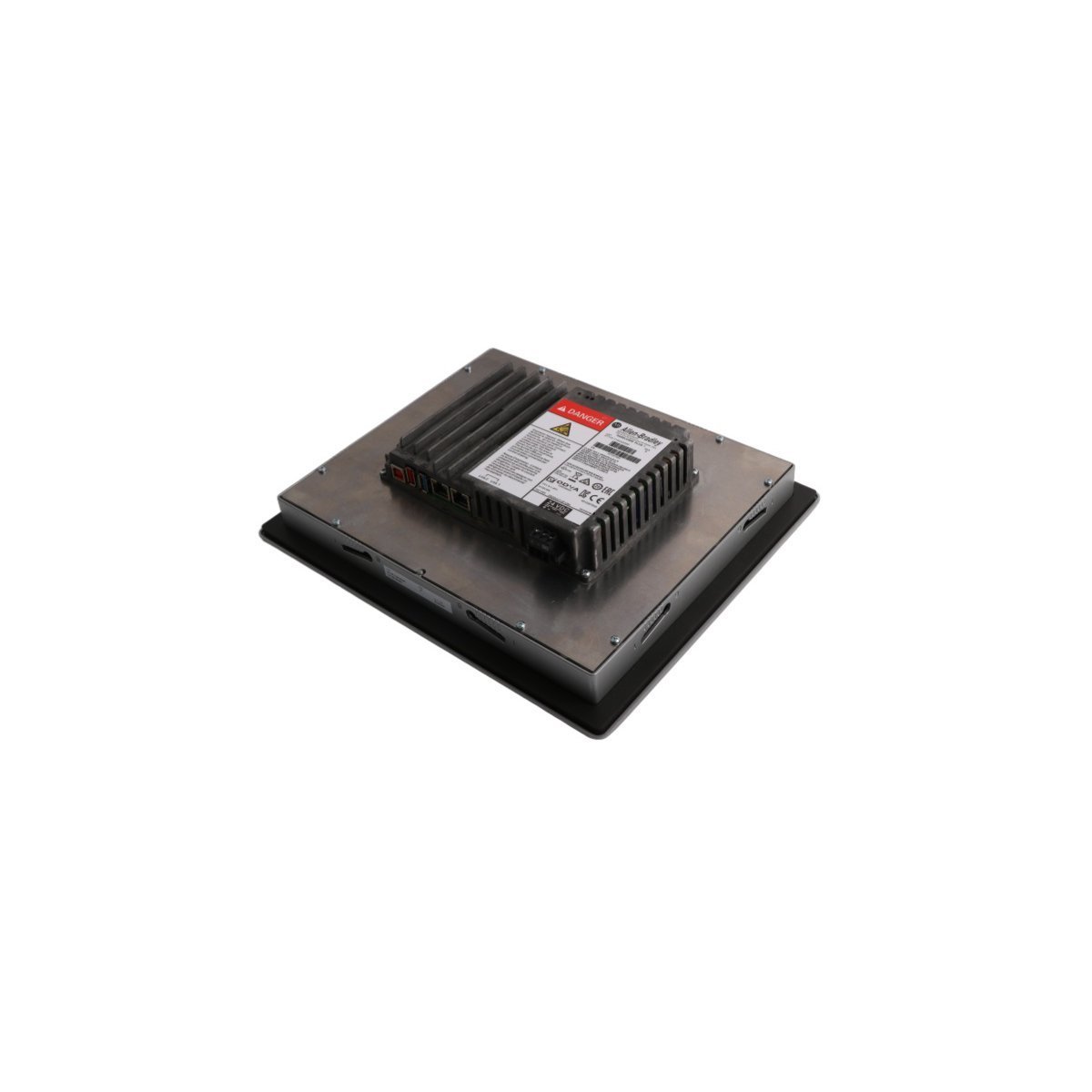
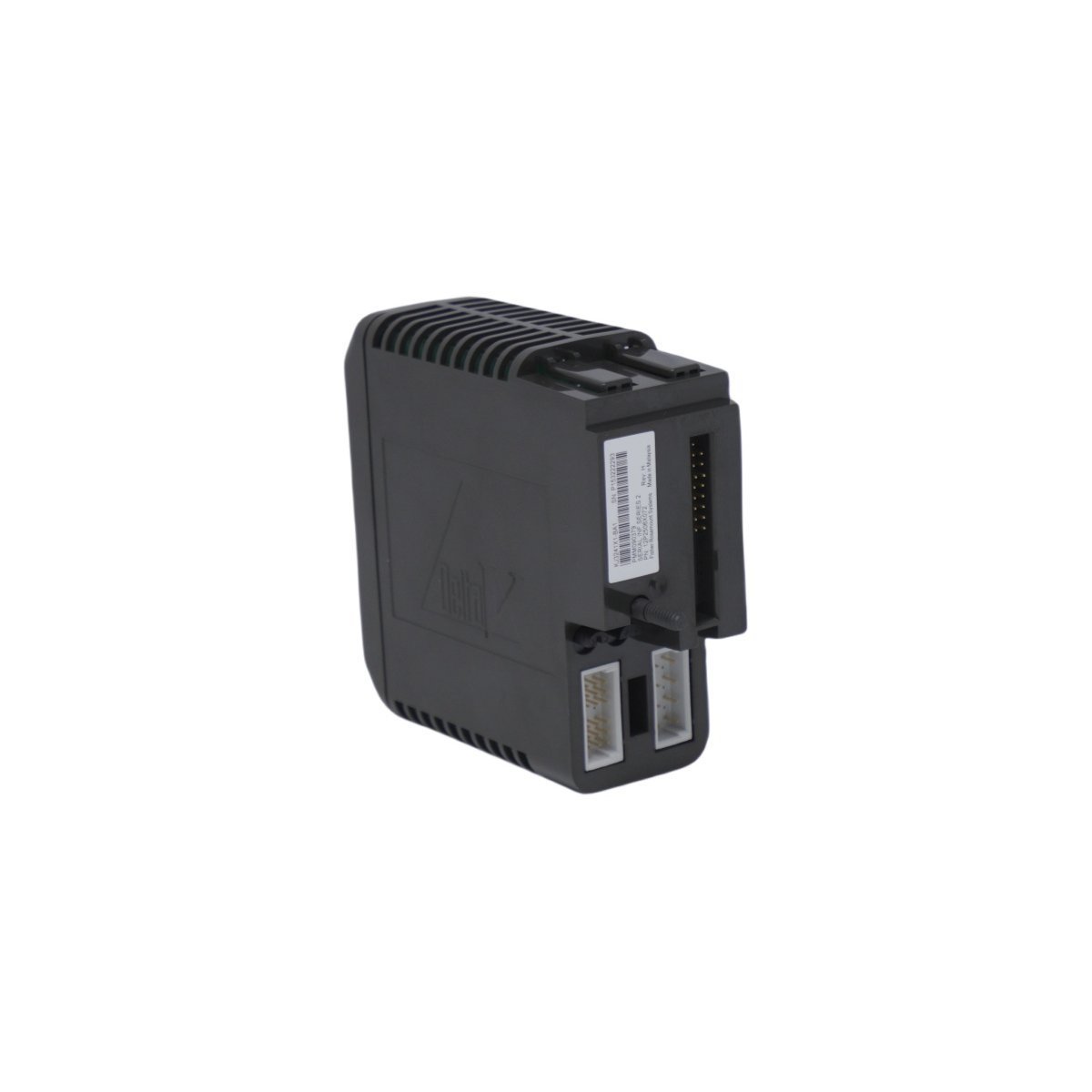
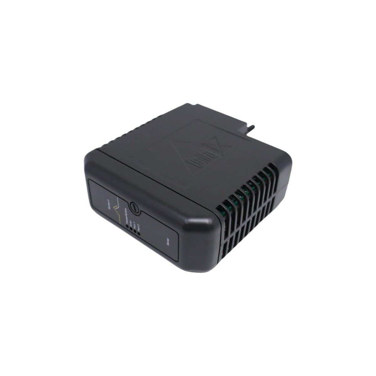
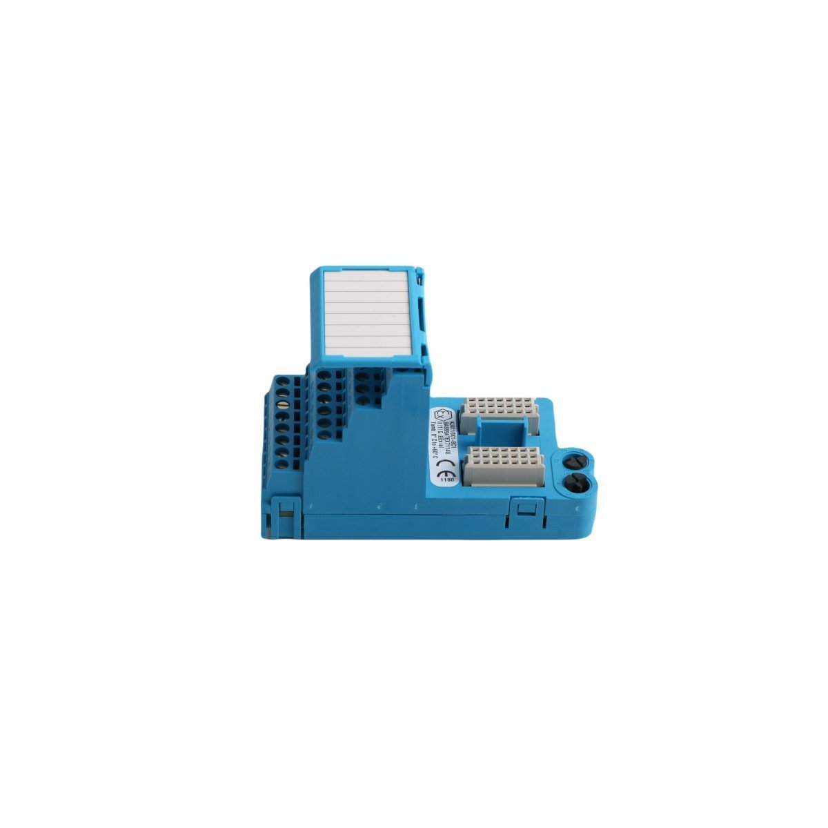
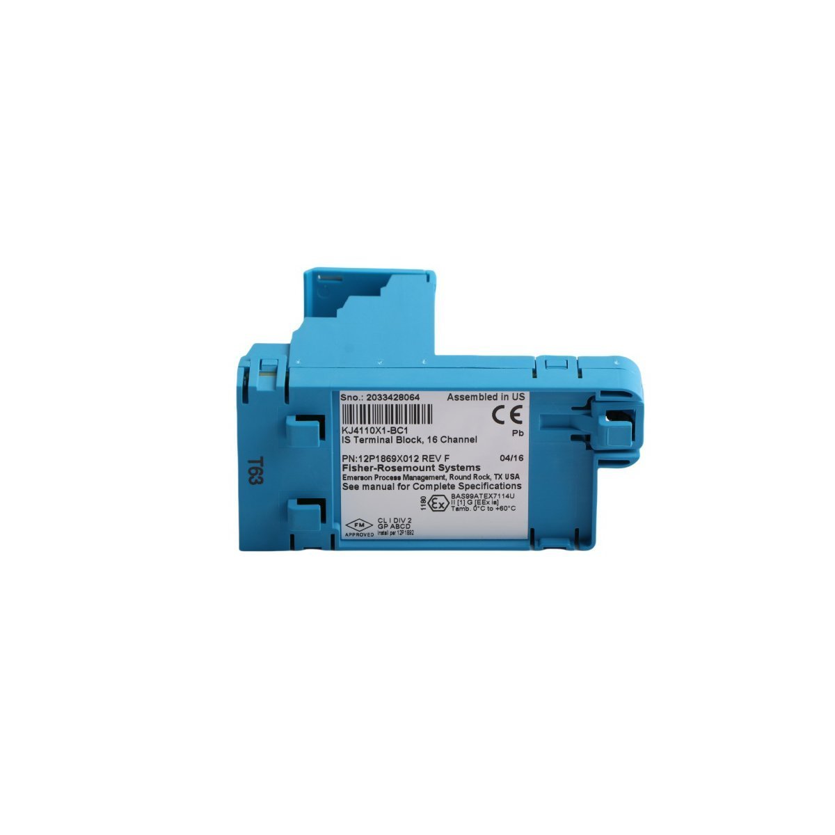
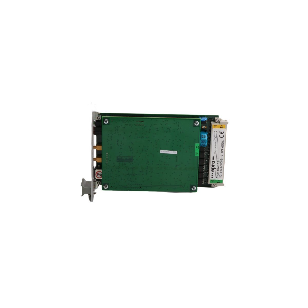
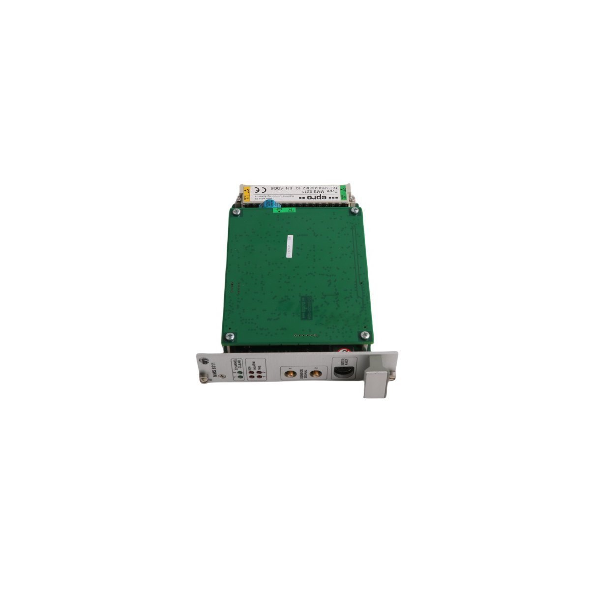
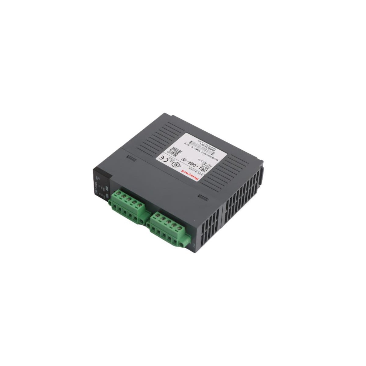
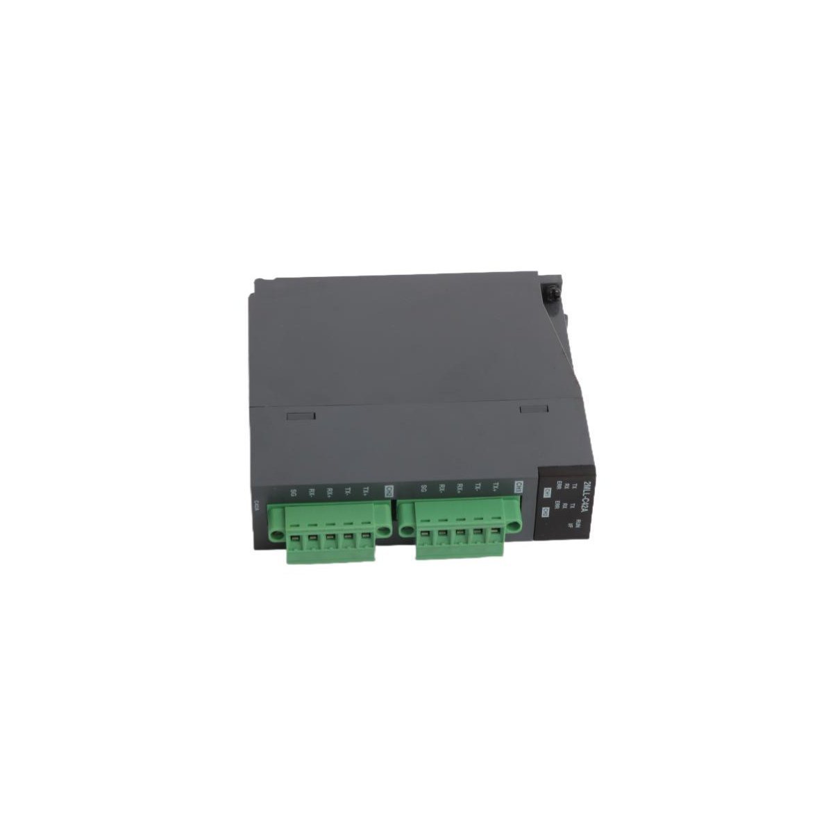
Allen-Bradley 2094-BM03-S Axis Module
Configured for high-performance motion control in Kinetix 6000 multi-axis drive systems, the Allen-Bradley 2094-BM03-S (2094-BM03-S Axis Module) provides direct physical and electrical execution for rotary and linear motor regulation.
Hardware Specifications
| Parameter | Specification |
| Model | 2094-BM03-S |
| Brand | Allen-Bradley |
| Origin | USA |
| Weight | 0.9 kg |
| Dimensions | 3.5 cm x 13 cm x 14.5 cm |
| Operating Temp | Standard industrial range |
| Power Consumption | 200 W continuous (dissipation) |
| Continuous Current | 21.2 A |
| Peak Current | 53.0 A |
| Power Output | 13.5 kW |
Industrial Control System Connectivity
The 2094-BM03-S integrates into industrial control platforms by utilizing high-speed backplane bus communication protocols for real-time motion synchronization. This modular architecture facilitates I/O density scaling within the drive cabinet, which allows the system to manage complex motion feedback loops efficiently. Furthermore, the module supports firmware flash compatibility, enabling engineers to update internal logic for specific application requirements. Consequently, the drive ensures deterministic response times during acceleration, deceleration, and power threshold excursions.Frequently Asked Questions (FAQ)
Q: Does this axis module support hot-swapping within the Kinetix 6000 power rail?A: No, you must isolate the drive system from all primary power sources and verify that the DC bus is fully discharged before you remove or insert the module to prevent damage to the backplane interface.Q: How does the module handle feedback signal integration?A: The 2094-BM03-S interfaces directly with motor feedback cables, processing auxiliary encoder signals to maintain precise position tracking and velocity regulation during operation.Field Installation Guidelines
- To begin with, ensure all power to the drive assembly is strictly isolated and that the DC bus voltage has dissipated to a safe level; consequently, this prevents accidental electrical discharge during handling.
- Subsequently, mount the module onto the dedicated Kinetix power rail; furthermore, ensure that the mechanical locking tabs engage securely to provide the necessary ground contact and structural stability.
- In addition, connect the motor feedback cables and interface wires to the front-panel terminals, ensuring that all shields are terminated at the designated ground lugs to suppress electromagnetic interference; meanwhile, verify the cable bend radius to prevent permanent fiber or conductor damage.
- Following physical mounting, perform a thorough check of all electrical connections before applying system power; by doing so, you minimize the risk of short-circuits on the backplane.
- Finally, confirm that the motion controller configuration matches the physical addressing and firmware version of the 2094-BM03-S to enable stable data exchange and command execution on the bus.