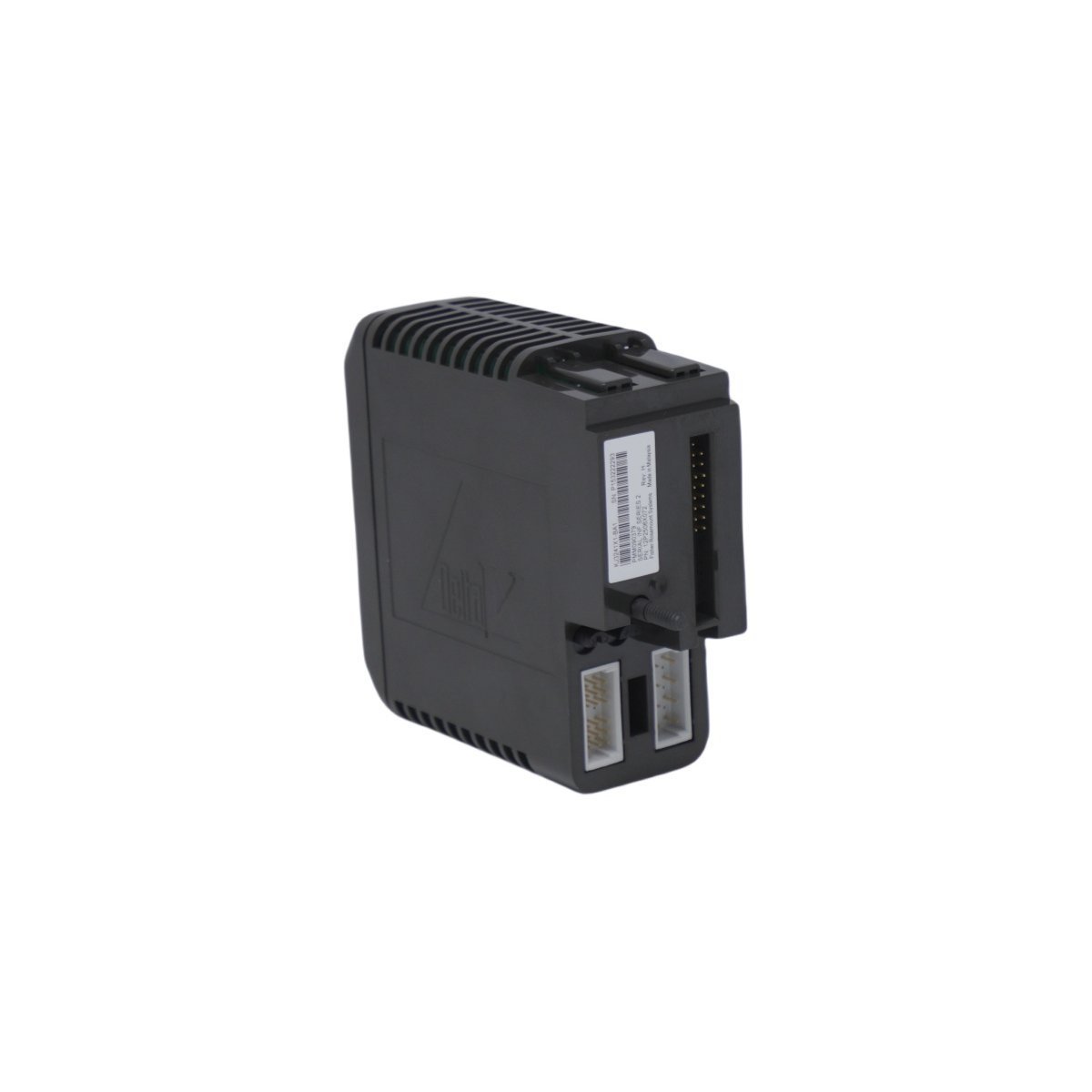
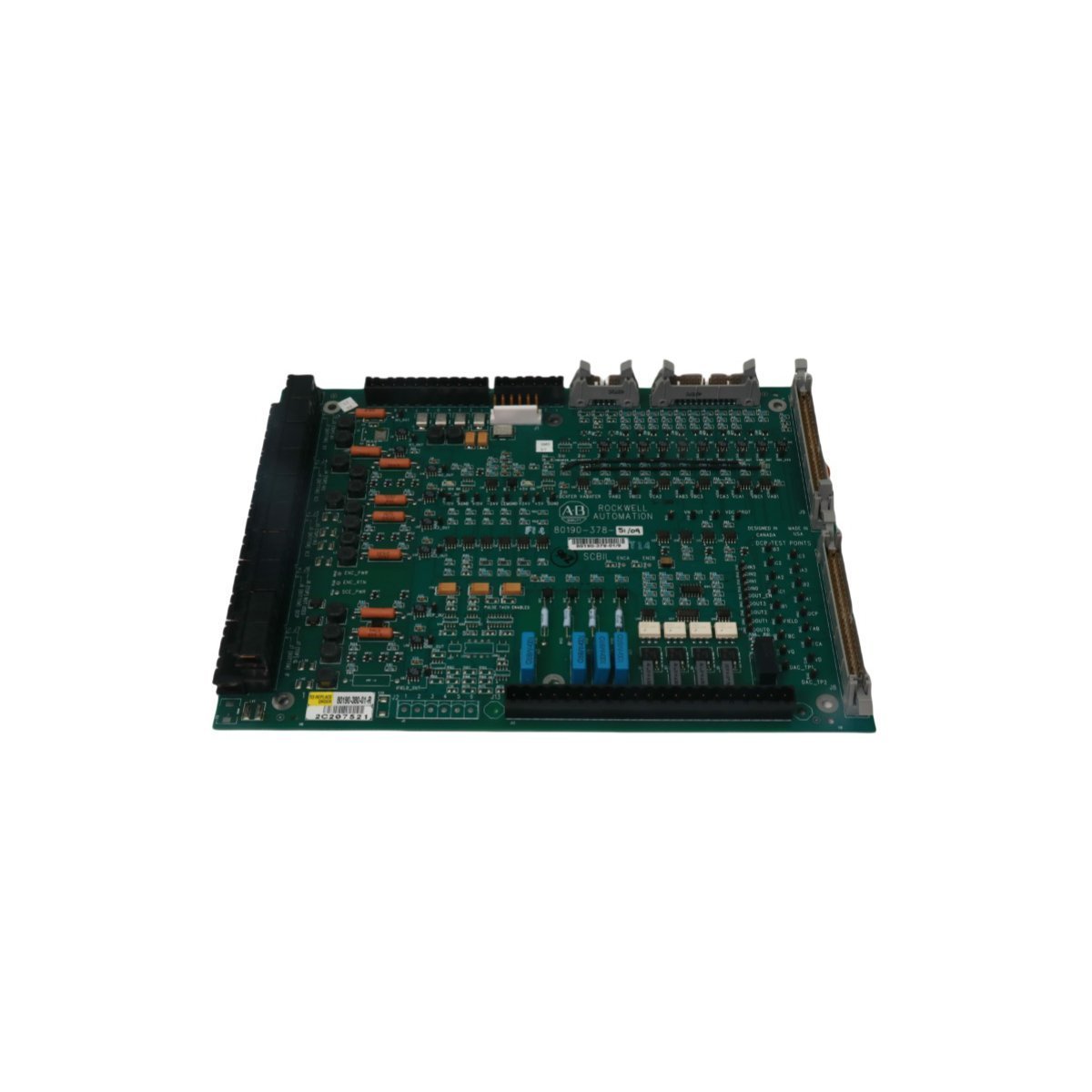
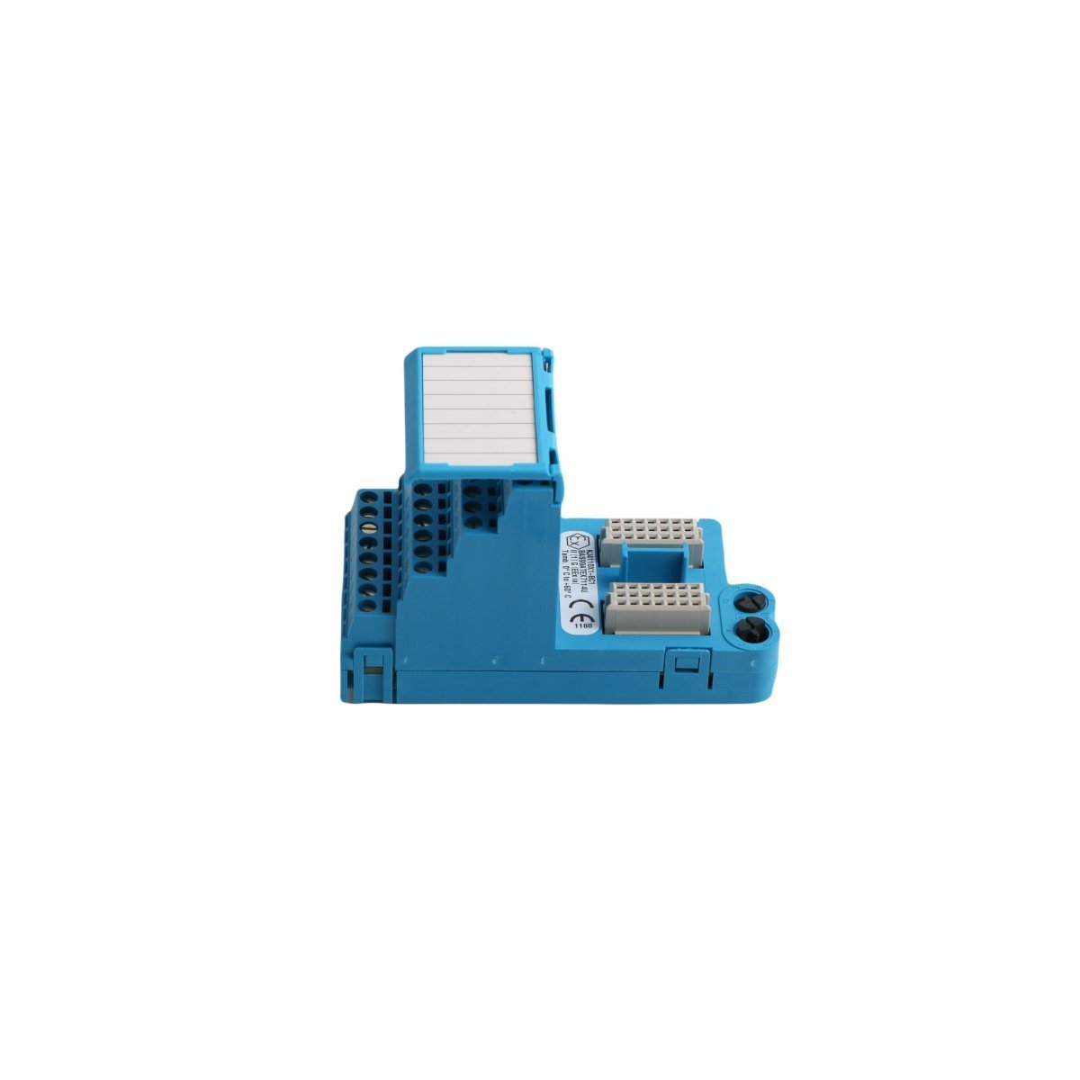
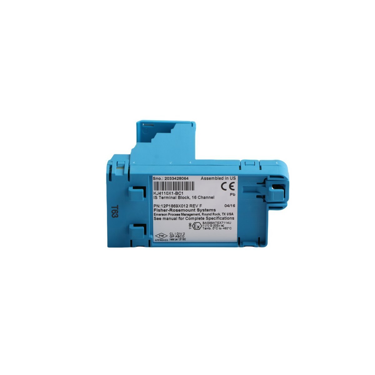
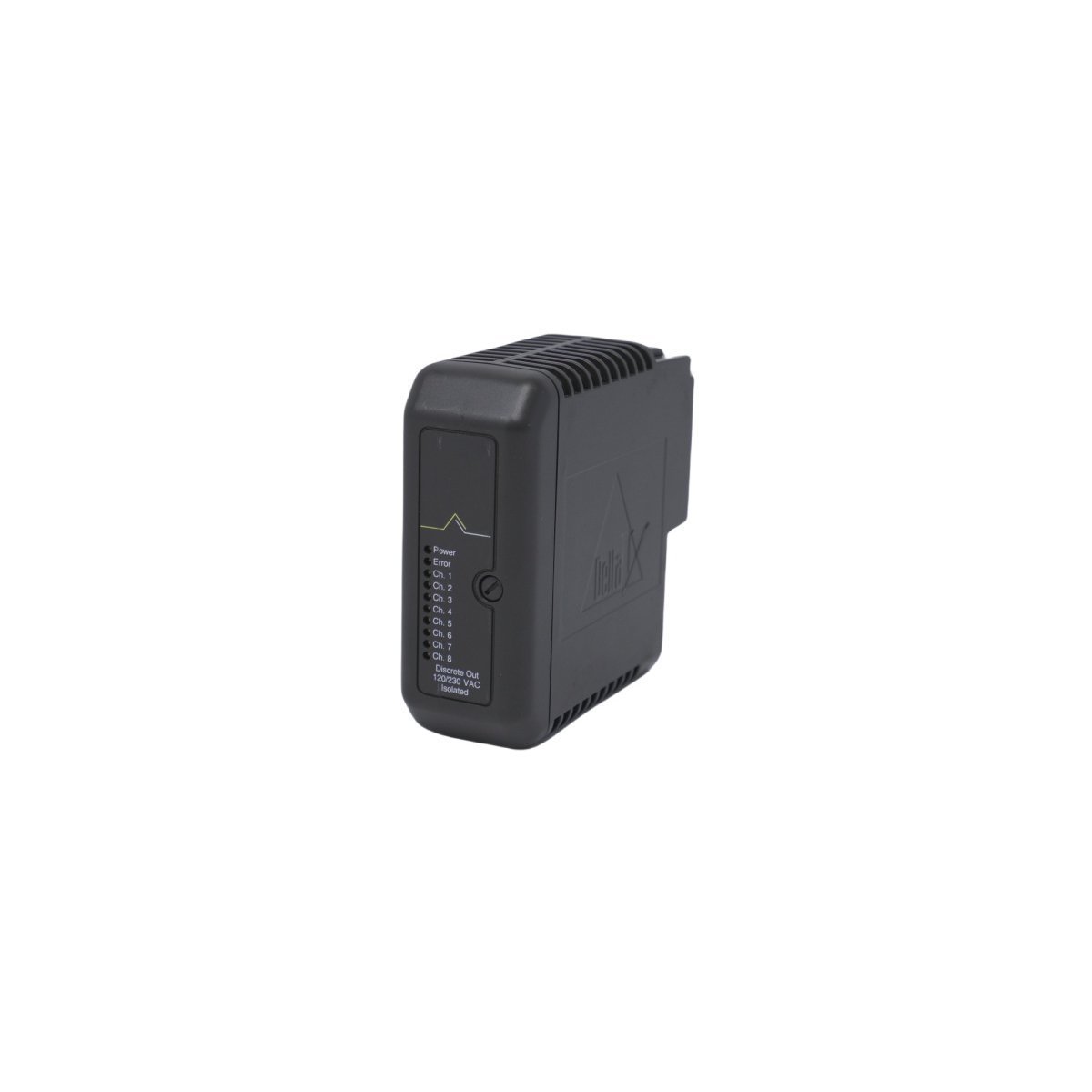
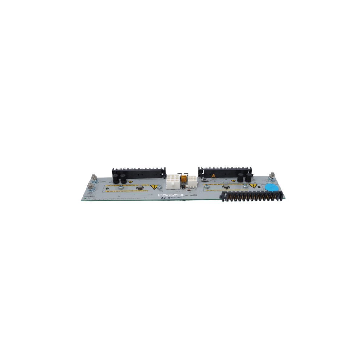
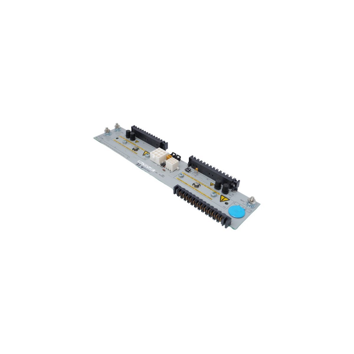
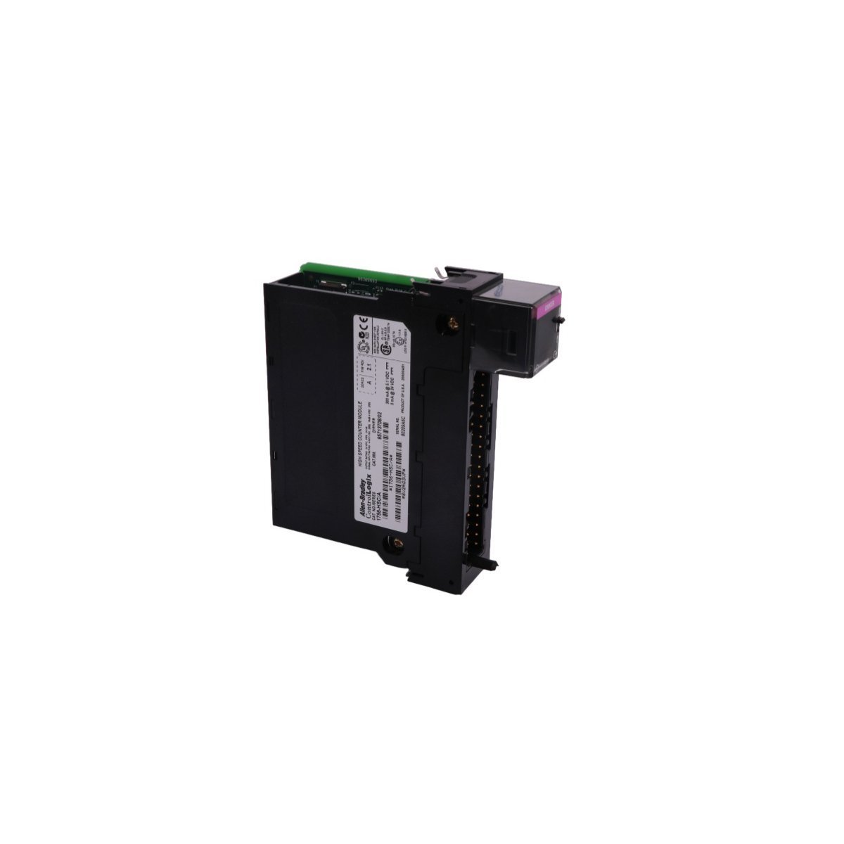
You are here:
SKU: SDCS-FEX-425-INT 3ADT209022R0001

ABB SDCS-FEX-425-INT 3ADT209022R0001 Control Field Exciter Board

Secure the brand new original stock ABB SDCS-FEX-425-INT 3ADT209022R0001 Control Field exciter board. Engineered for robust 24 VDC DC drive field control loops. Verified authentic parts ready for global shipping. Request technical support now.

Configured for specific technical task execution in DCS networks, the ABB SDCS-FEX-425-INT (3ADT209022R0001 Control Field exciter board) provides direct physical/electrical execution.

Hardware Specifications

ParameterSpecification
ModelSDCS-FEX-425-INT 3ADT209022R0001
BrandABB
OriginSweden
Module TypeControl Field Exciter Board
System PlatformDCS / DC Drives
Supply Voltage24 VDC
Power Consumption10-20 W
Output Voltage Range0-250 VDC
Output Current Range0-20 A
Accuracy+-0.5% of full scale
Input-to-Output Isolation2500 VAC
Analog Inputs4-20 mA or 0-10 V
Operating Temp-20 to +70 deg C
Storage Temp-40 to +85 deg C
Humidity5-95% non-condensing
Weight0.66 kg
Dimensions27 x 11.5 x 6 cm

Industrial Control & Drive Connectivity

The SDCS-FEX-425-INT 3ADT209022R0001 integrates within the power converter framework to govern localized field winding excitation loops. The hardware design enables rapid backplane bus communication velocity to sync execution loops with primary controller parameters. High I/O density scaling allows processing of multi-range analog inputs alongside native Profinet / EtherNet/IP deterministic networks, maintaining critical control loop alignment under variable dynamic load demands.

Frequently Asked Questions

Q: What are the exact isolation limitations for the 3ADT209022R0001 analog inputs?

A: The board provides an input-to-output isolation rating of 2500 VAC. Signal paths must be routed through shielded terminal paths to prevent high-frequency transients from bridging this boundary.

Q: Is online hot-swap allowed for the SDCS-FEX-425-INT under active drive operation?

A: No. Due to active inductive field currents of up to 20 A and high-voltage DC risks, power to the drive assembly must be disconnected and fully discharged prior to extraction.


Field Installation Guidelines

  • Shielding and Grounding: Route all 4-20 mA and 0-10 V analog input lines via individual twisted-pair shielded cables. Bond the cable shield to the cabinet earth terminal block on the enclosure entry side only.
  • DIN-Rail Mount Stability: Secure the board chassis to the structural backplate or DIN-rail system using rigid metal brackets. Ensure clearance dimensions of 27 x 11.5 x 6 cm are strictly maintained with no physical obstruction to air passage.
  • Thermal Management: When operating near the +70 deg C thermal threshold, incorporate forced-air ventilation inside the cabinet enclosure to prevent local hotspots and maintain the component’s internal conversion efficiency.