Sale!
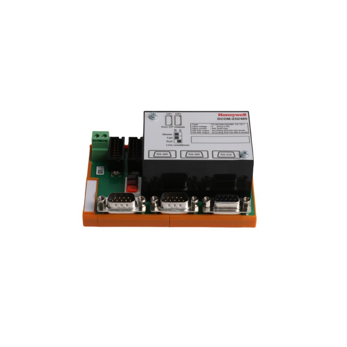
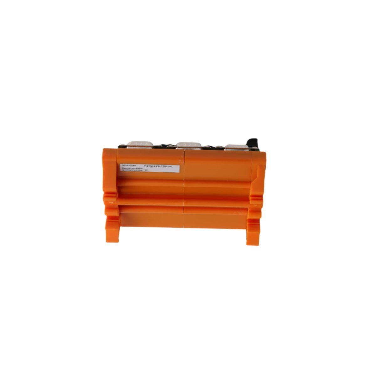
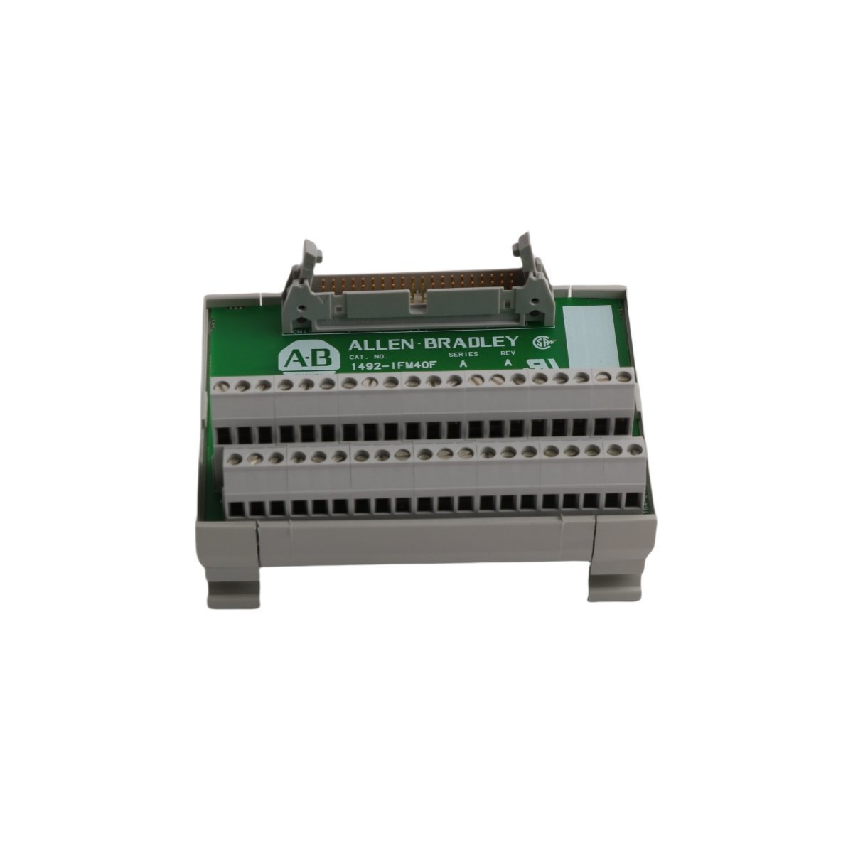
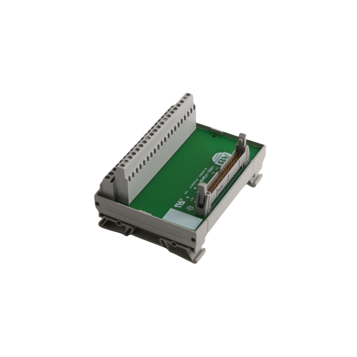
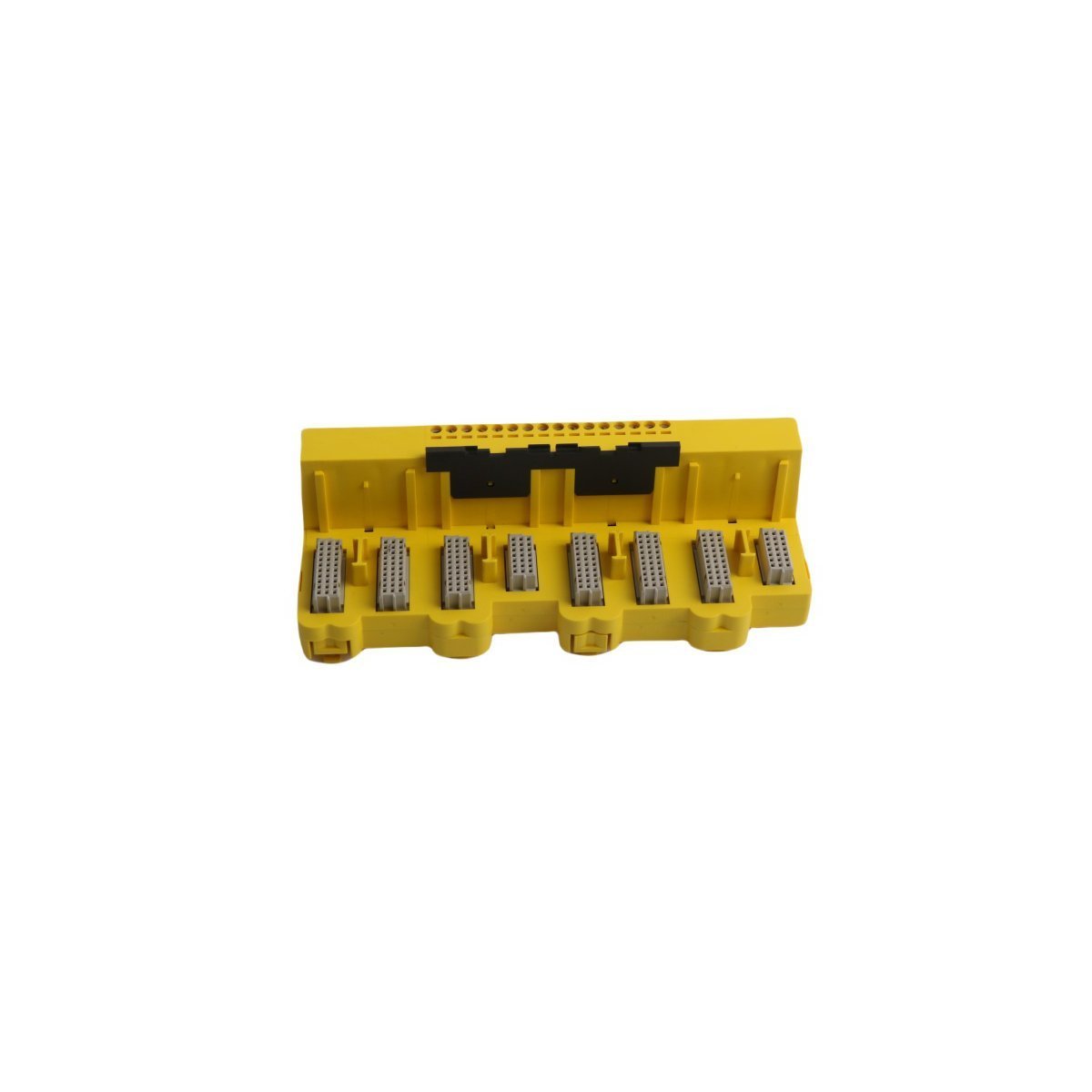
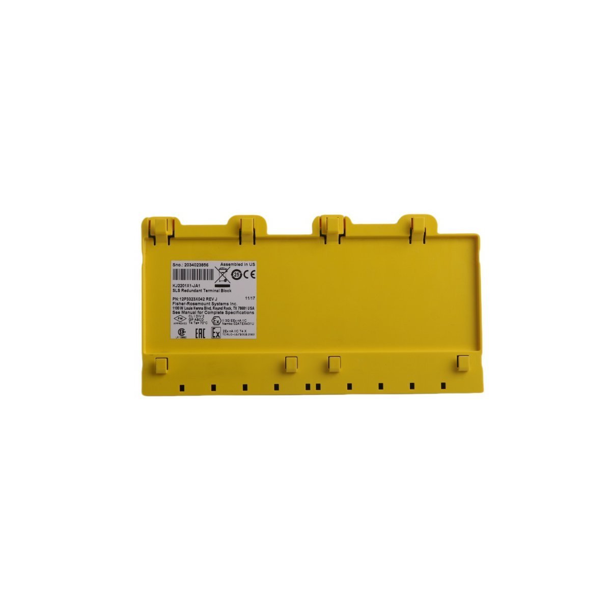
Honeywell FC-DCOM-232/485 Safety System Interface Module
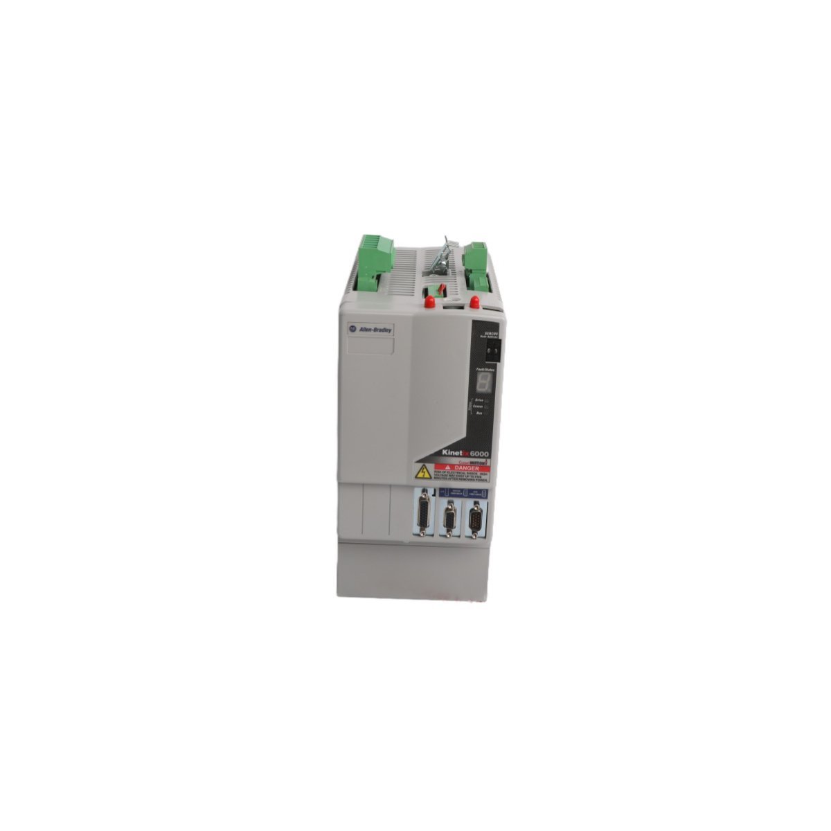
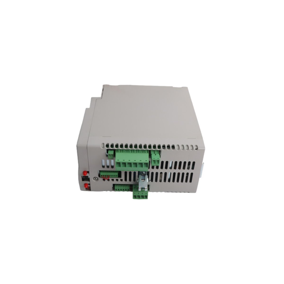
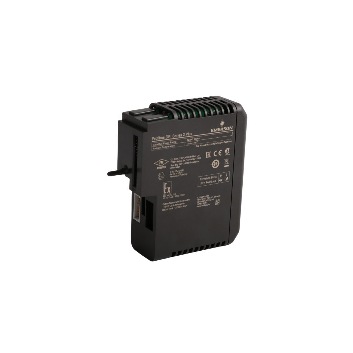
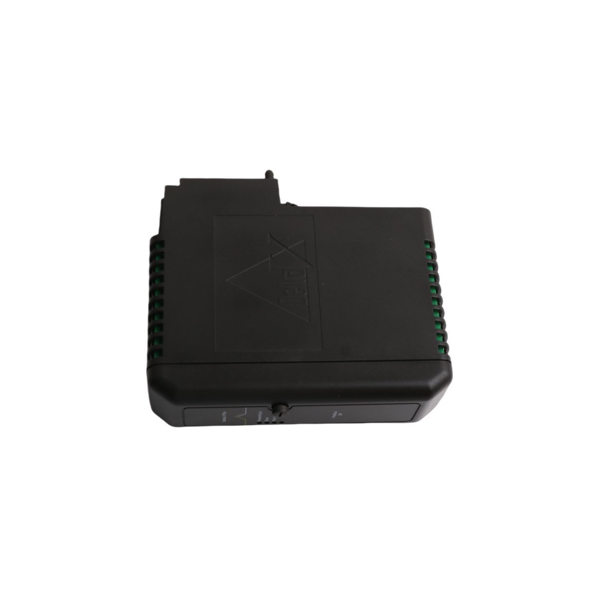
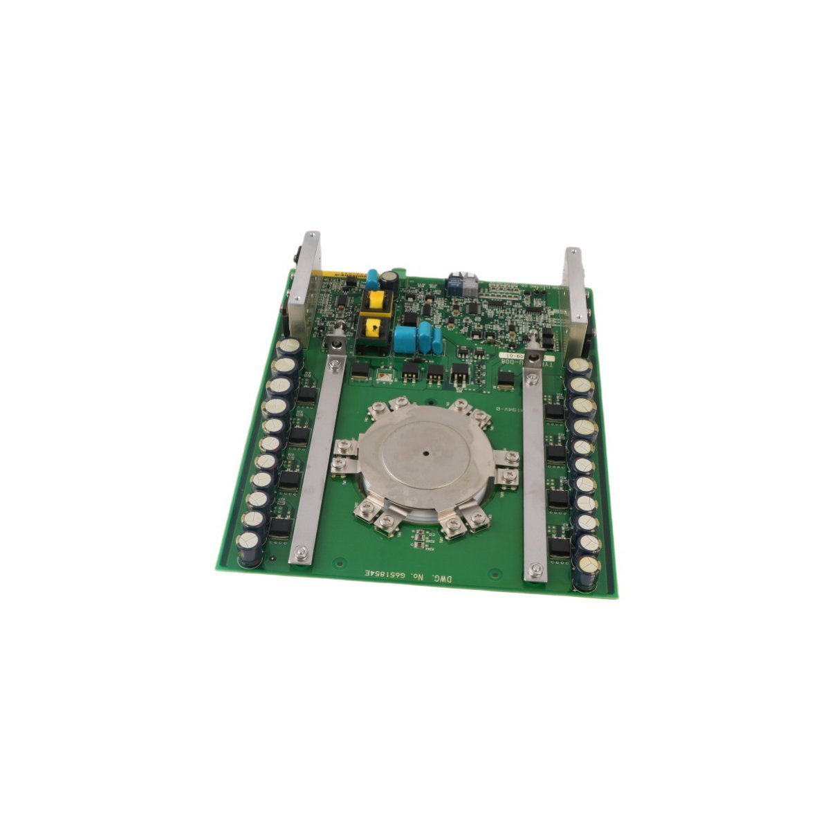
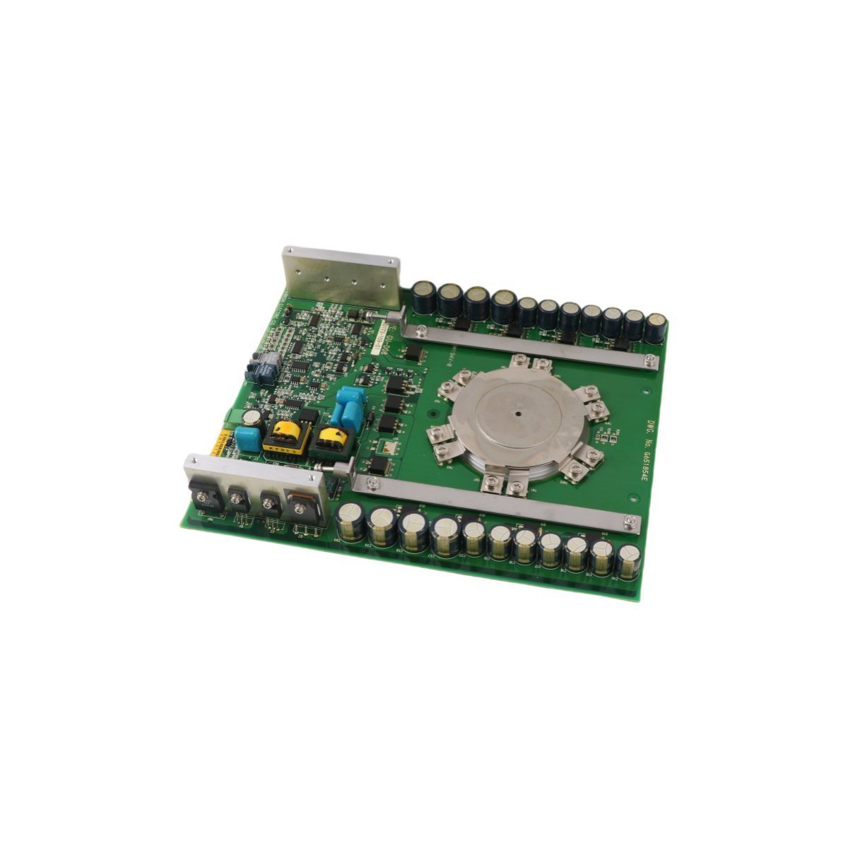
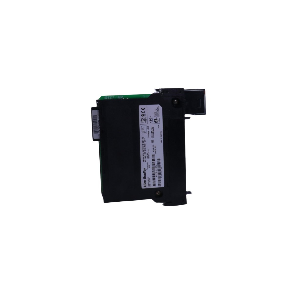
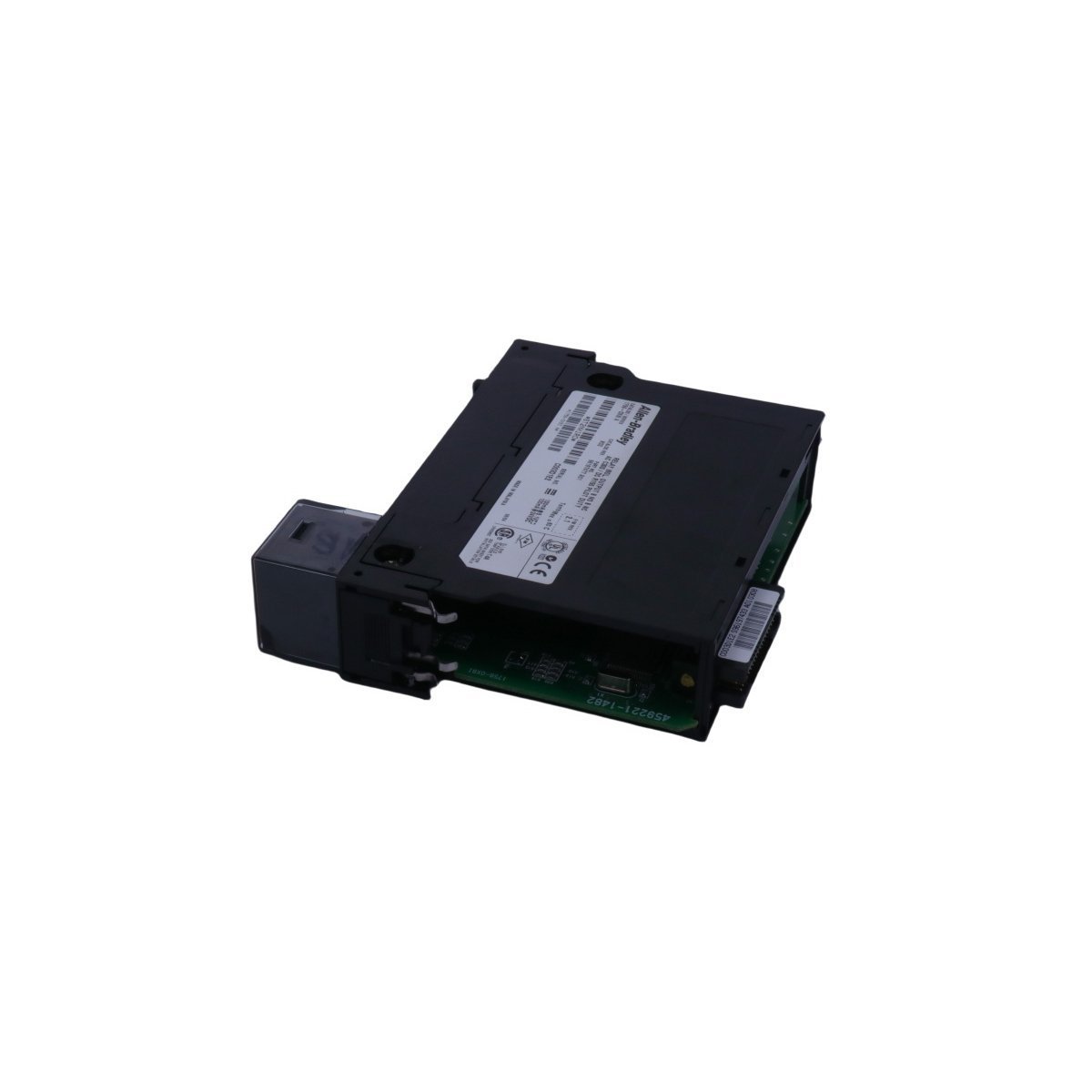
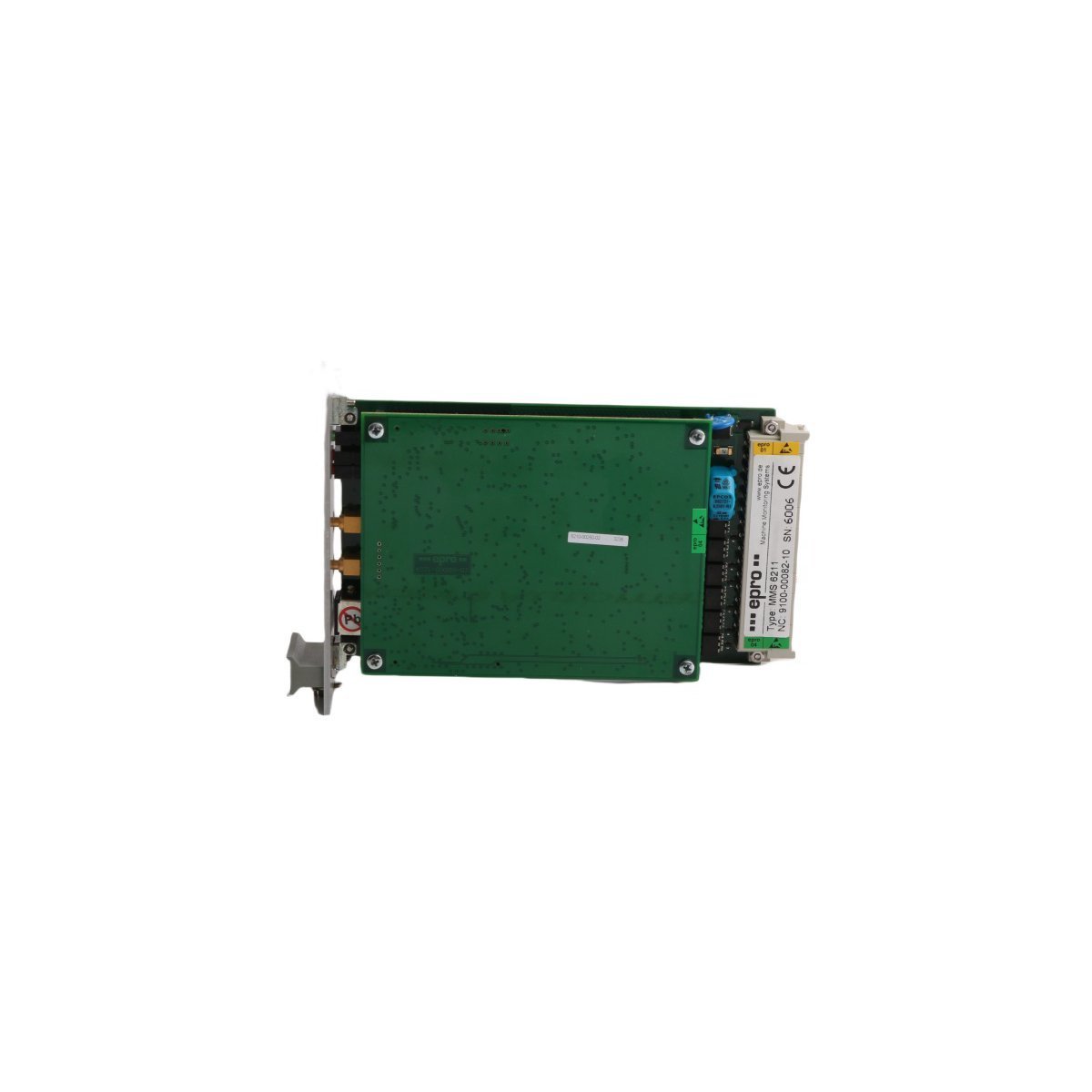
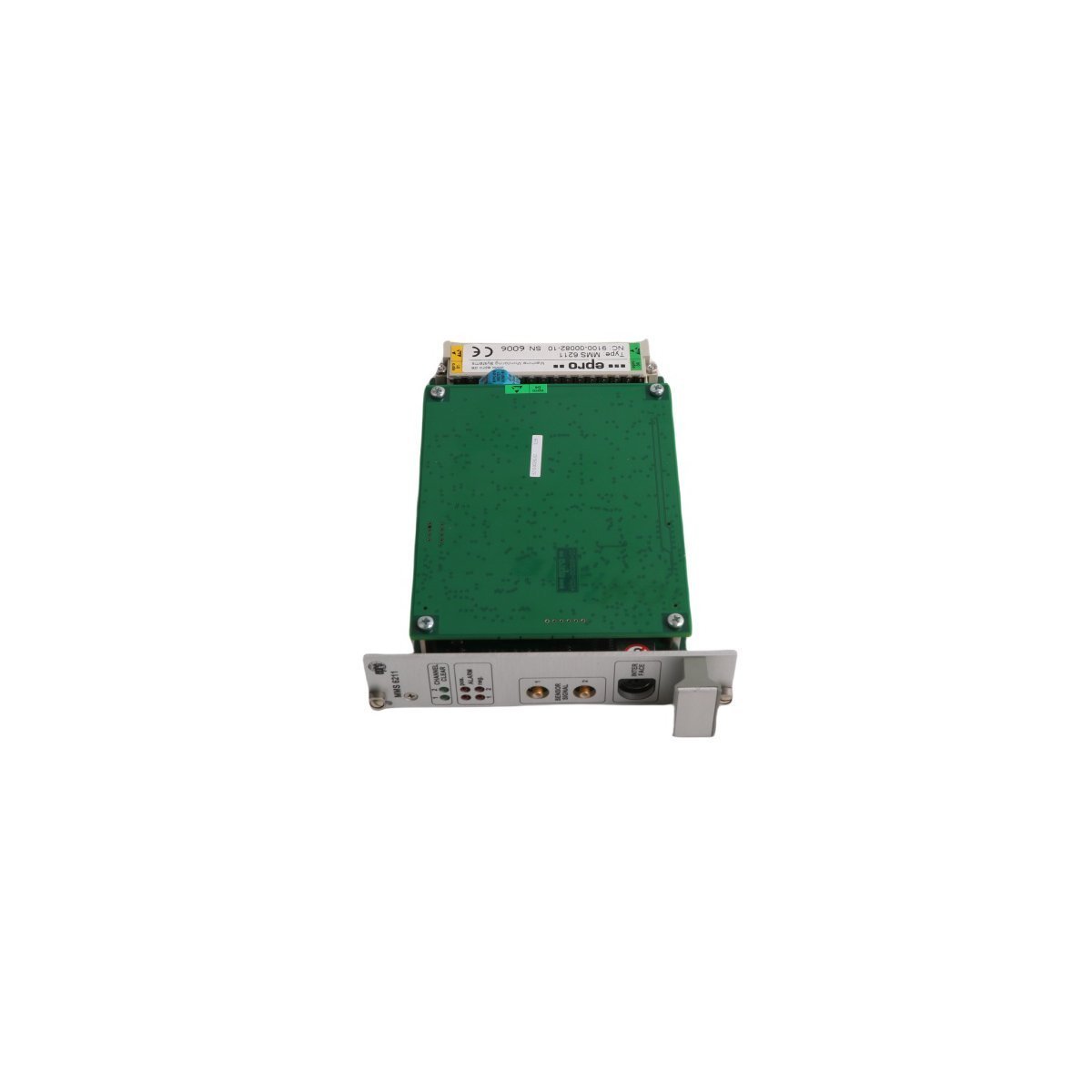
The Honeywell FC-DCOM-232/485, also cataloged as the DCOM-232/485 Interface Module, operates as a dedicated hardware component for serial protocol translation between RS-232 and RS-485 communication channels within Honeywell DCS safety system platforms.
Hardware Specifications
| Parameter | Specification |
|---|---|
| Model | FC-DCOM-232/485 |
| Base Model | DCOM-232/485 |
| Brand | Honeywell |
| Origin | USA |
| Module Type | Interface Module |
| Weight | 0.14 kg |
| Dimensions | 11 x 7 x 6 cm |
| HS Code | 8537101190 |
| Communication Protocols | RS-232, RS-485 |
| Minimum Order Quantity | 1 |
Channel Isolation & Signal Conditioning
The FC-DCOM-232/485 interface module incorporates dedicated channel-to-channel isolation circuitry to mitigate common-mode voltage offsets across extended physical serial links. During serial data exchange between RS-232 point-to-point lines and multi-drop RS-485 networks, internal galvanic barriers prevent ground loop currents from propagating into central DCS backplane logic. The hardware maintains signal integrity and differential transmission levels across long-distance field cable runs without inducing loop noise or data corruption.Frequently Asked Questions
Q: What physical interfaces are converted by the FC-DCOM-232/485 module?A: The module performs bi-directional physical level translation between standard point-to-point RS-232 signals and differential multi-drop RS-485 serial communication lines.Q: How does the module handle ground potential differences on long field runs?A: Integrated channel-to-channel isolation decouples the field serial interface from internal logic circuitry, suppressing ground loop noise and protecting backplane electronics.Field Installation Guidelines
- Mounting and Enclosure: Install the module inside an IP54 or NEMA 12 rated protective enclosure to safeguard components from industrial airborne contaminants and ambient moisture.
- Shield Grounding: Connect serial cable drain wires directly to the designated cabinet earth ground bar at a single point to minimize electrical interference.
- Wiring Separation: Route low-voltage RS-232/RS-485 serial communications cabling through dedicated conduits, maintaining physical separation from high-voltage AC power lines and motor drives.
- Terminal Engagement: Ensure all wiring terminals are secured with specified torque limits to prevent intermittent communication dropouts caused by vibration.