Sale!
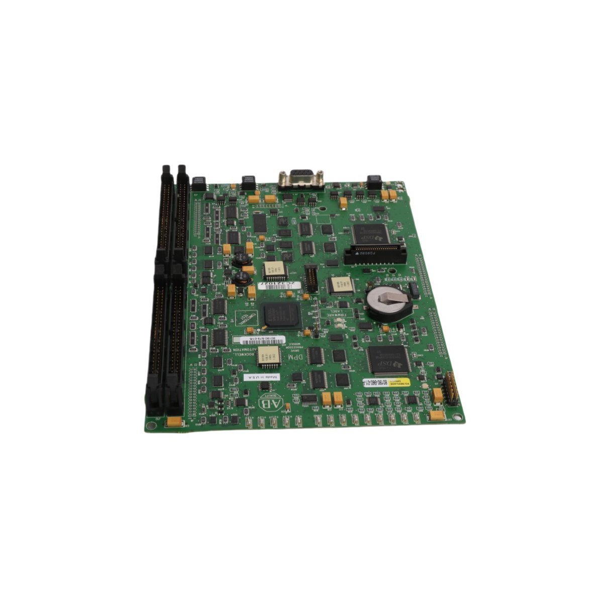
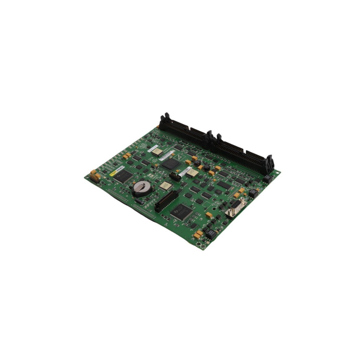
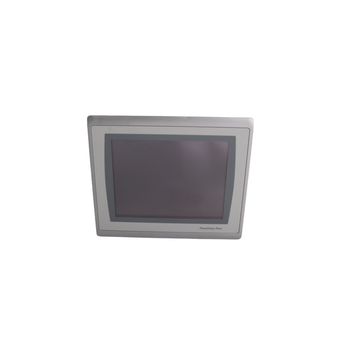
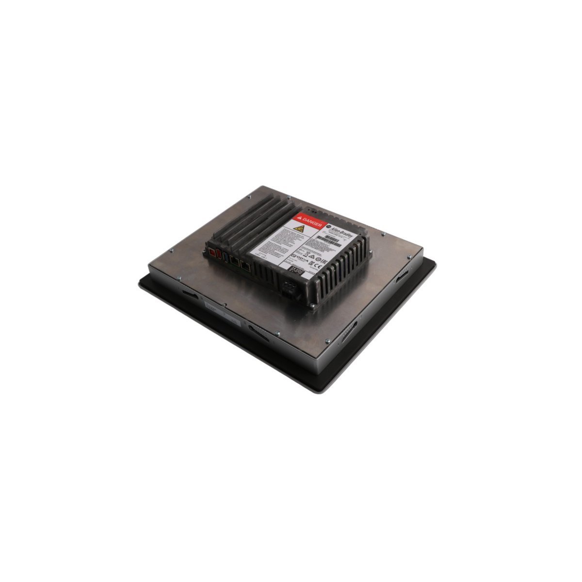
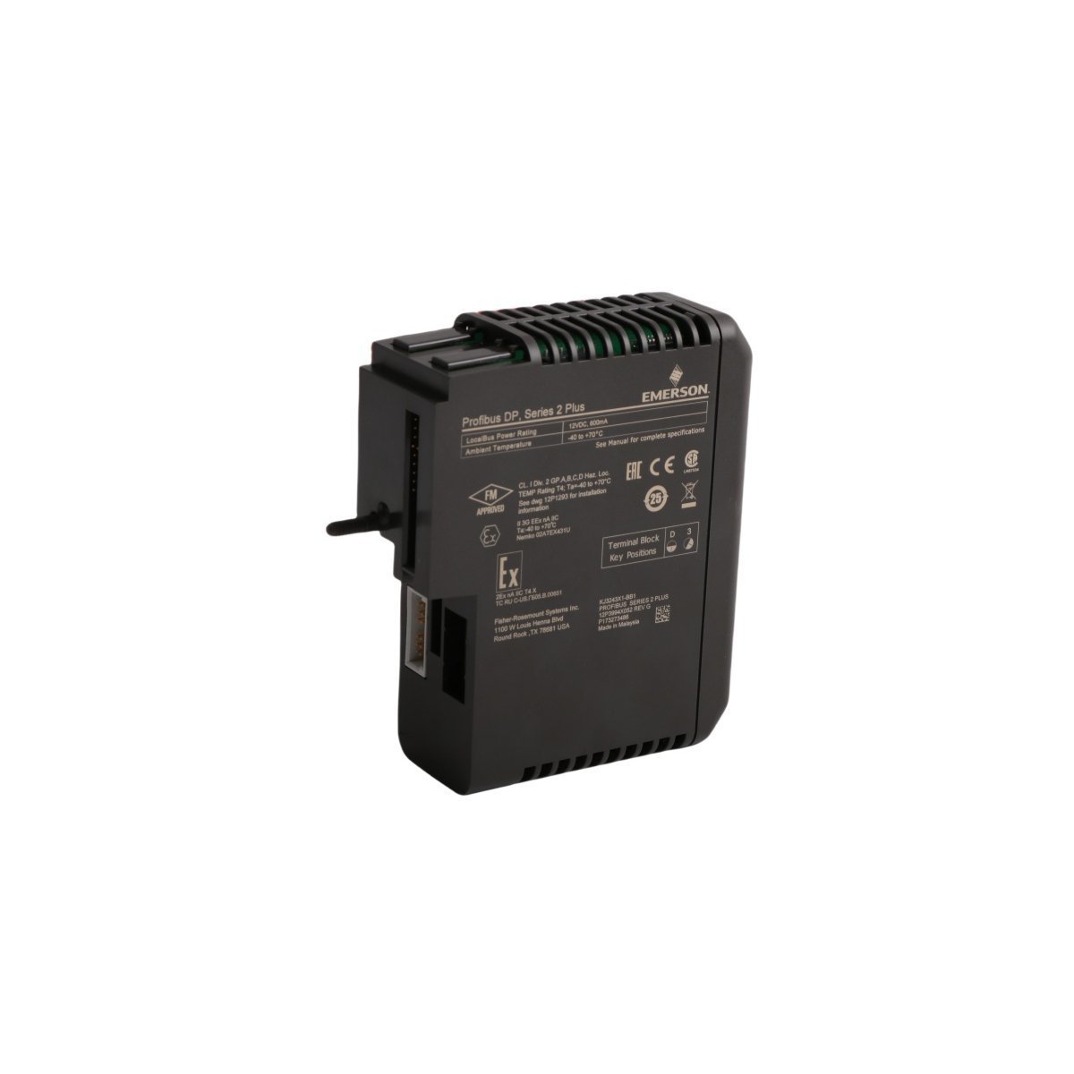
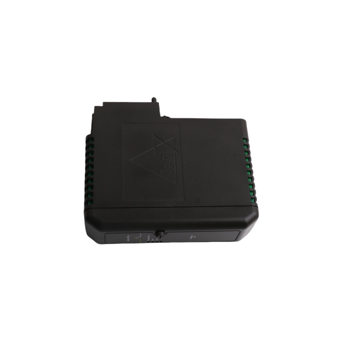
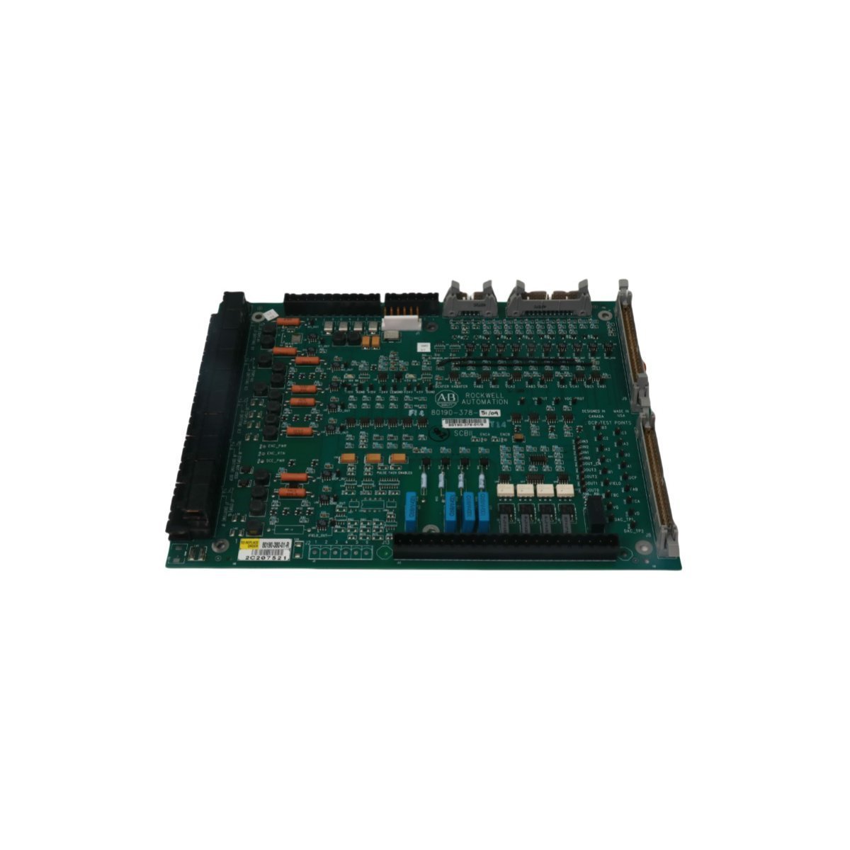
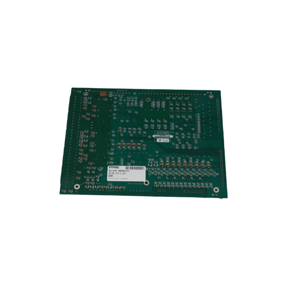
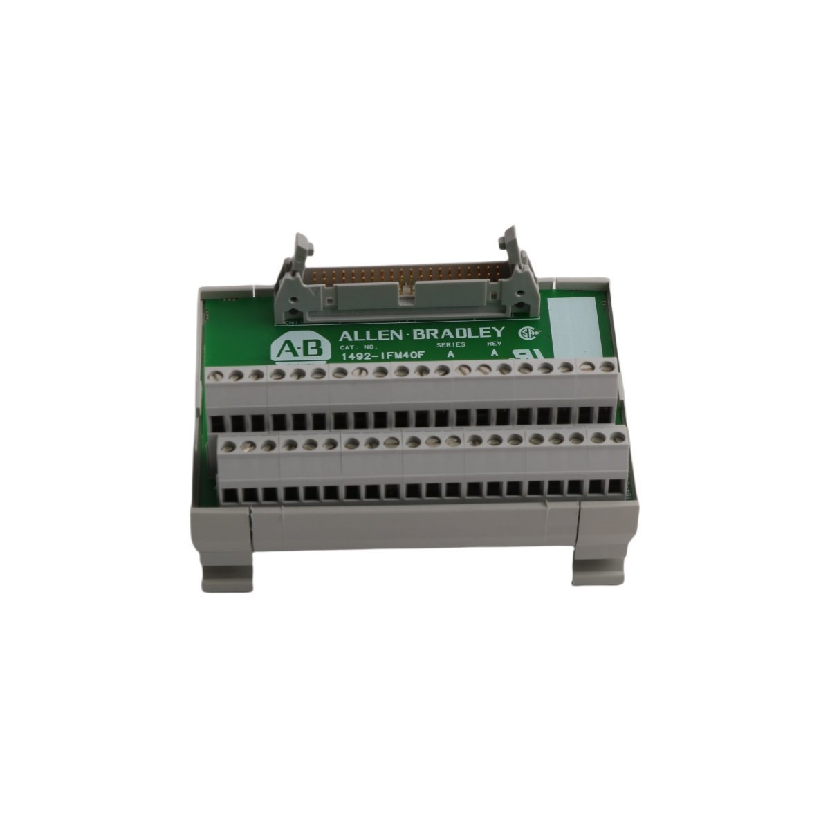
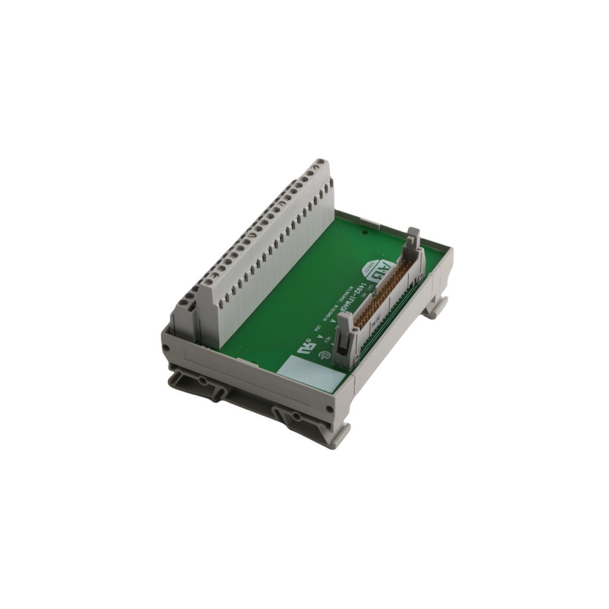
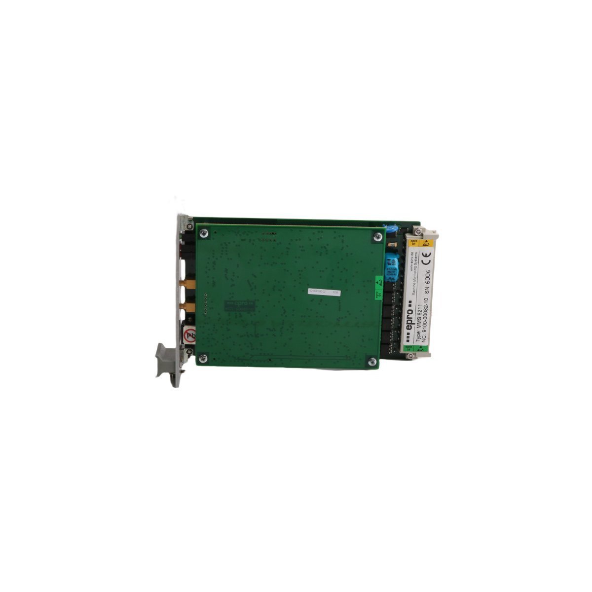
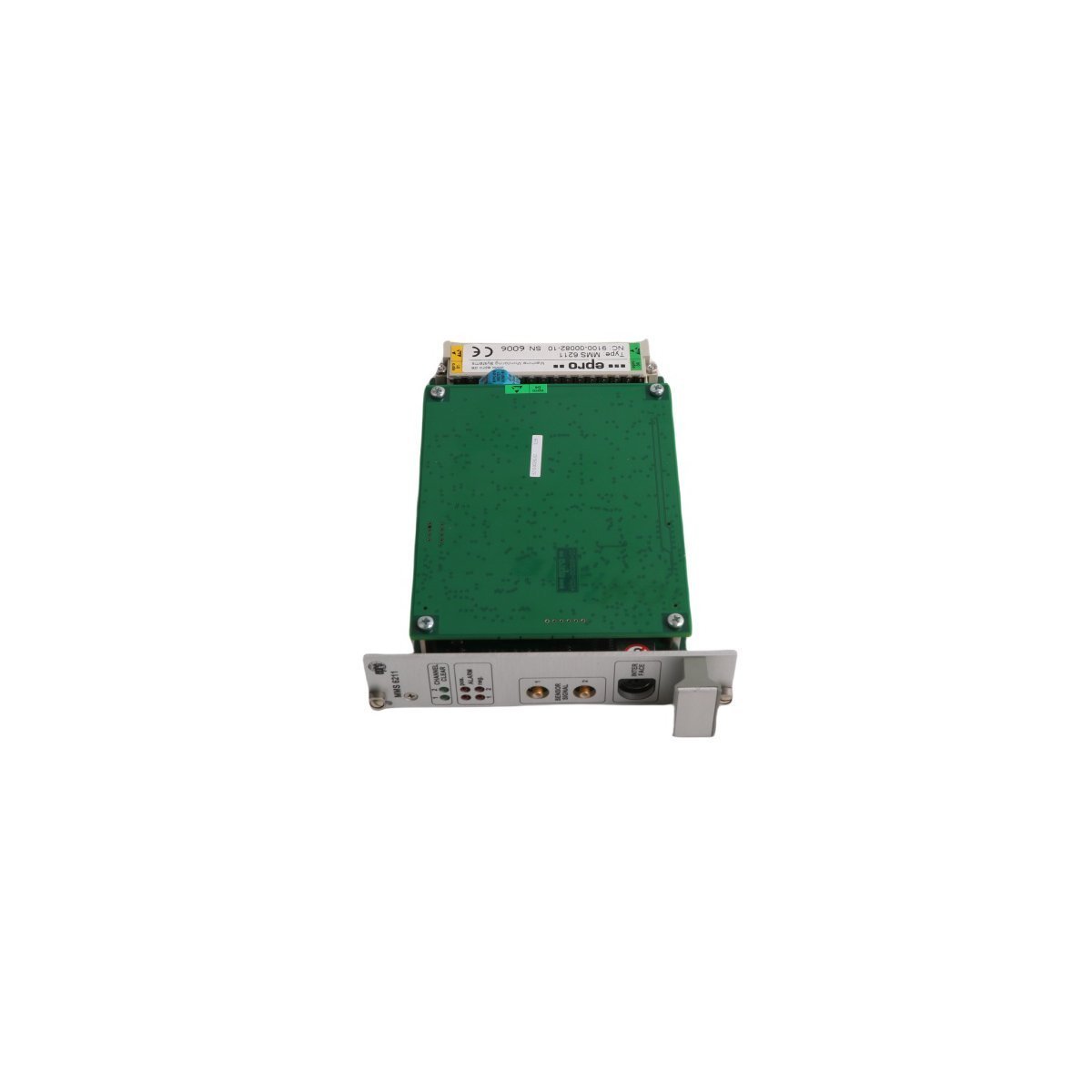
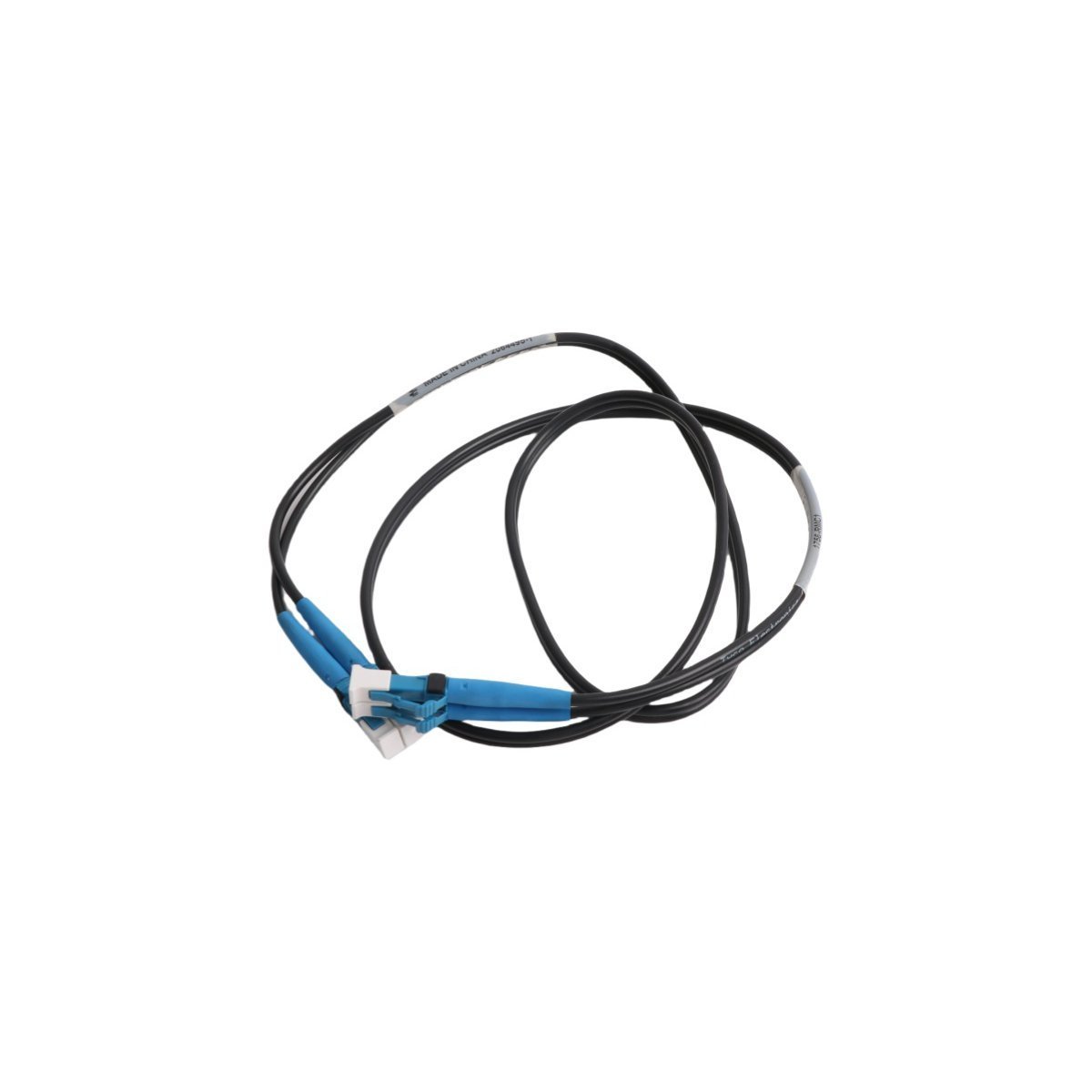
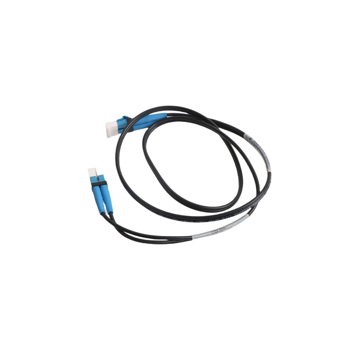
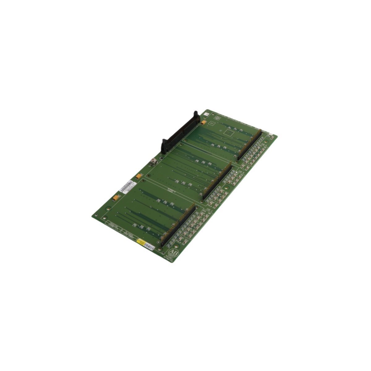
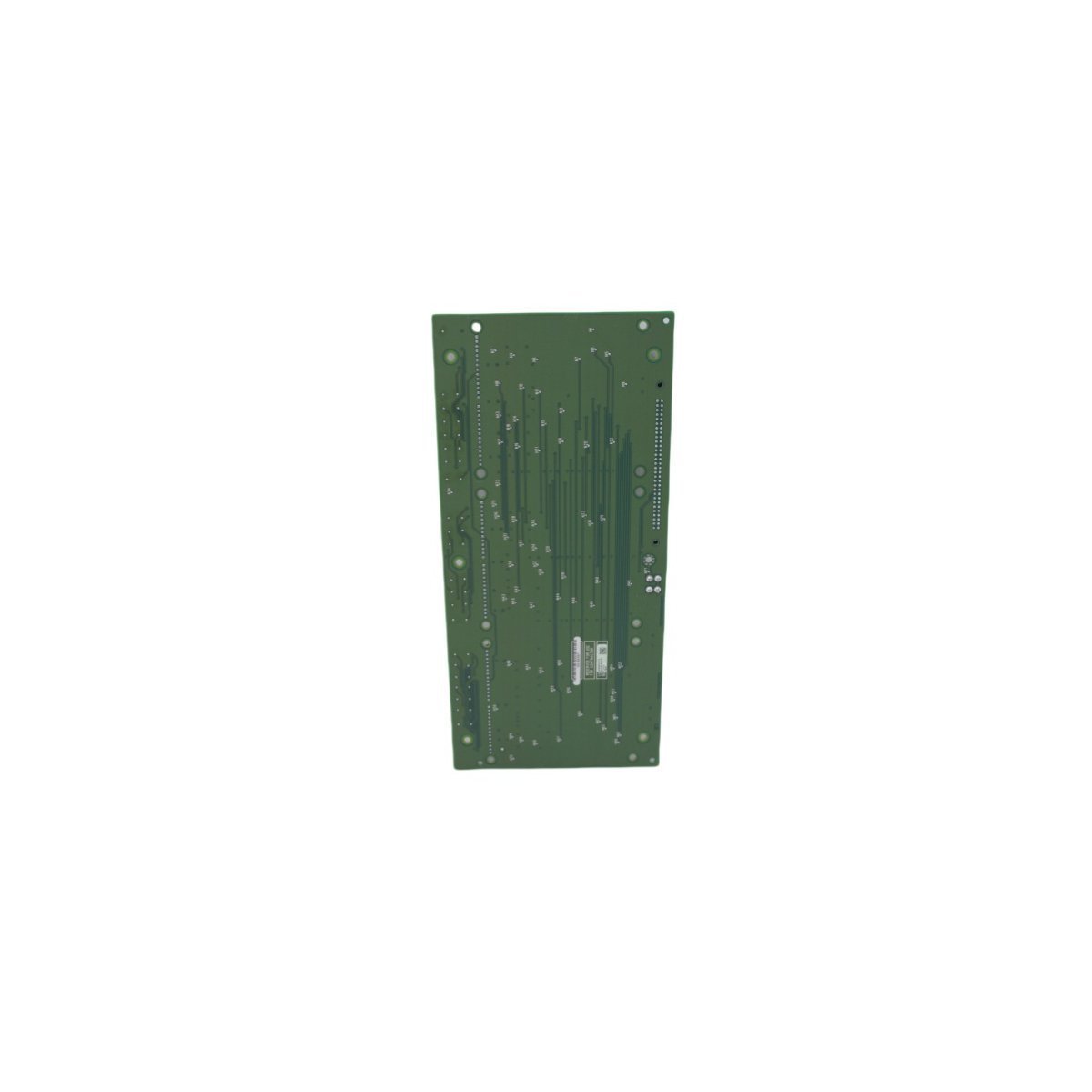
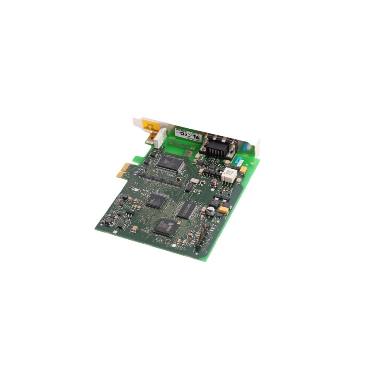
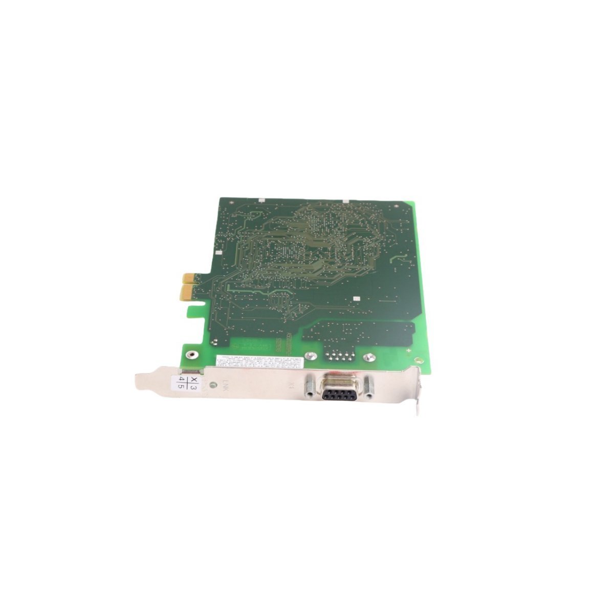
Allen Bradley 80190-560-01-R PC Board
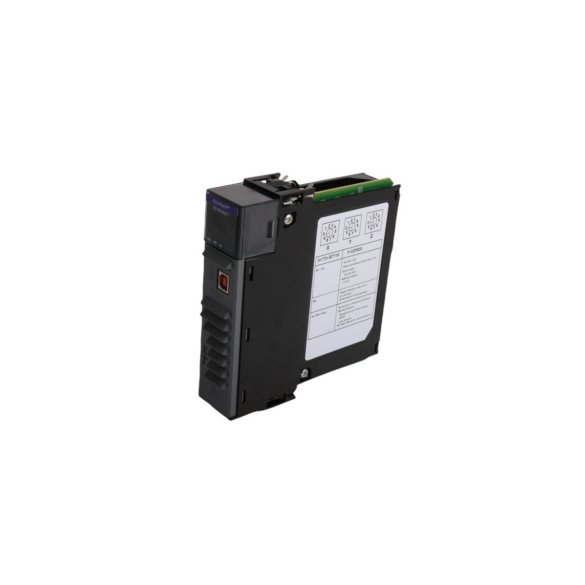
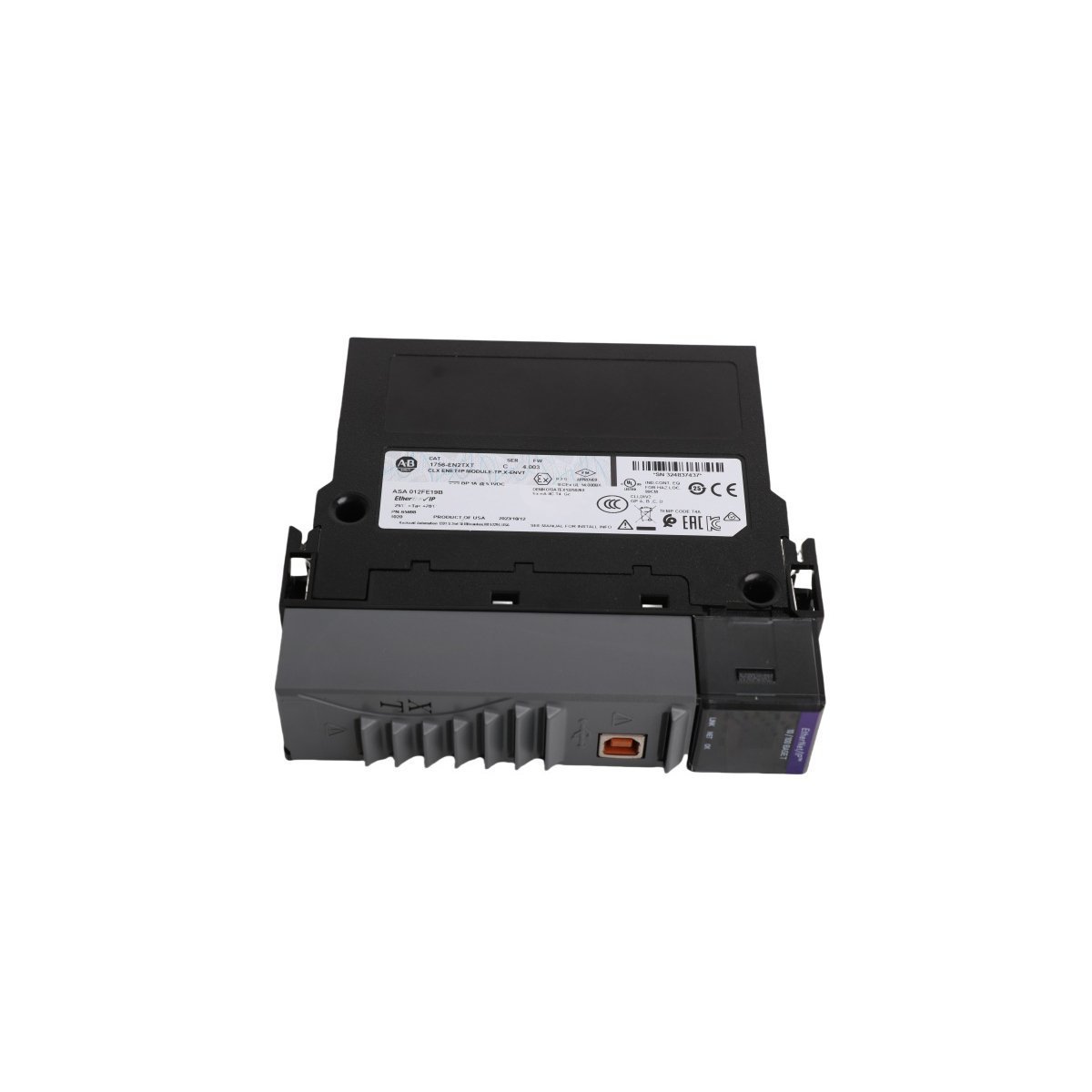
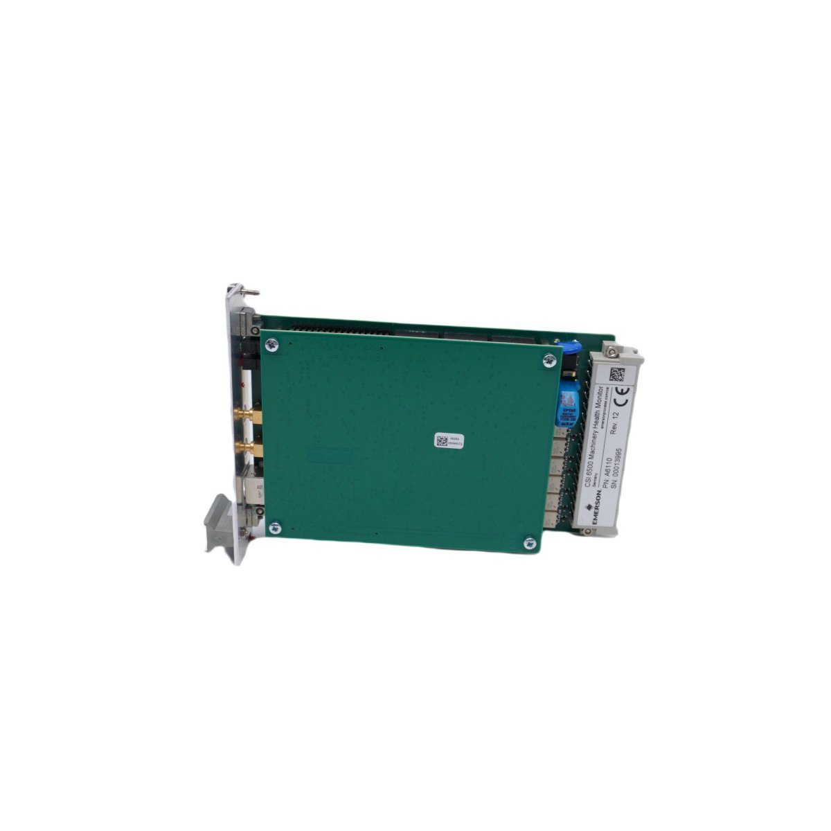
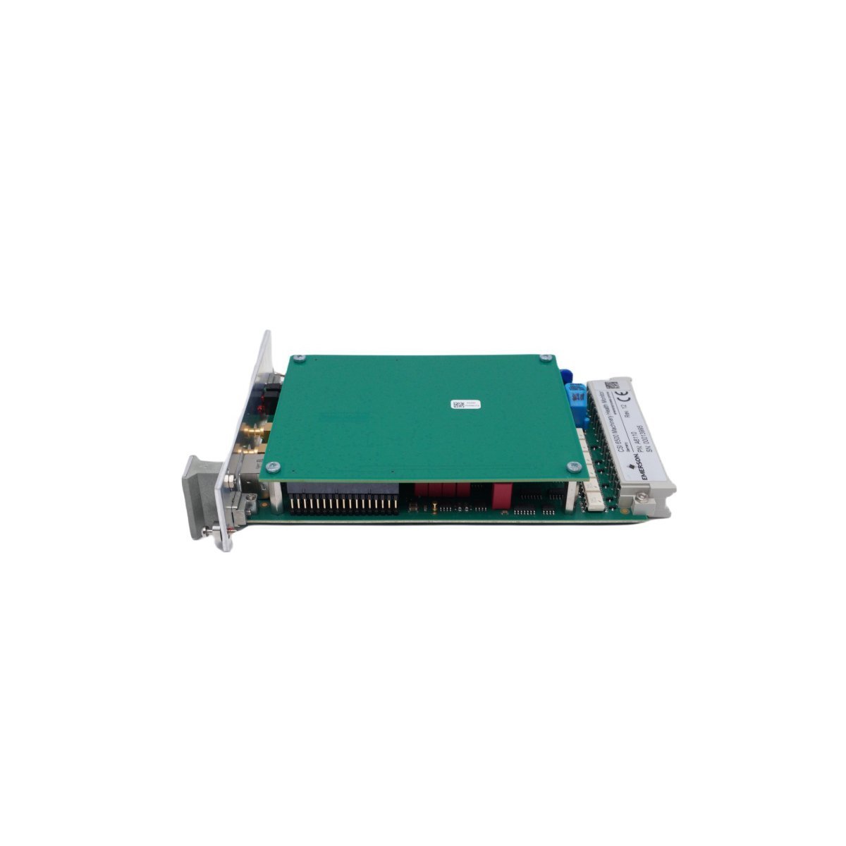
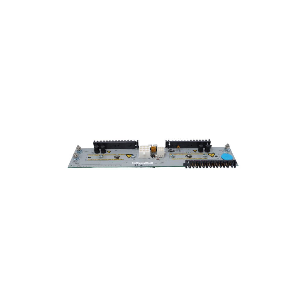
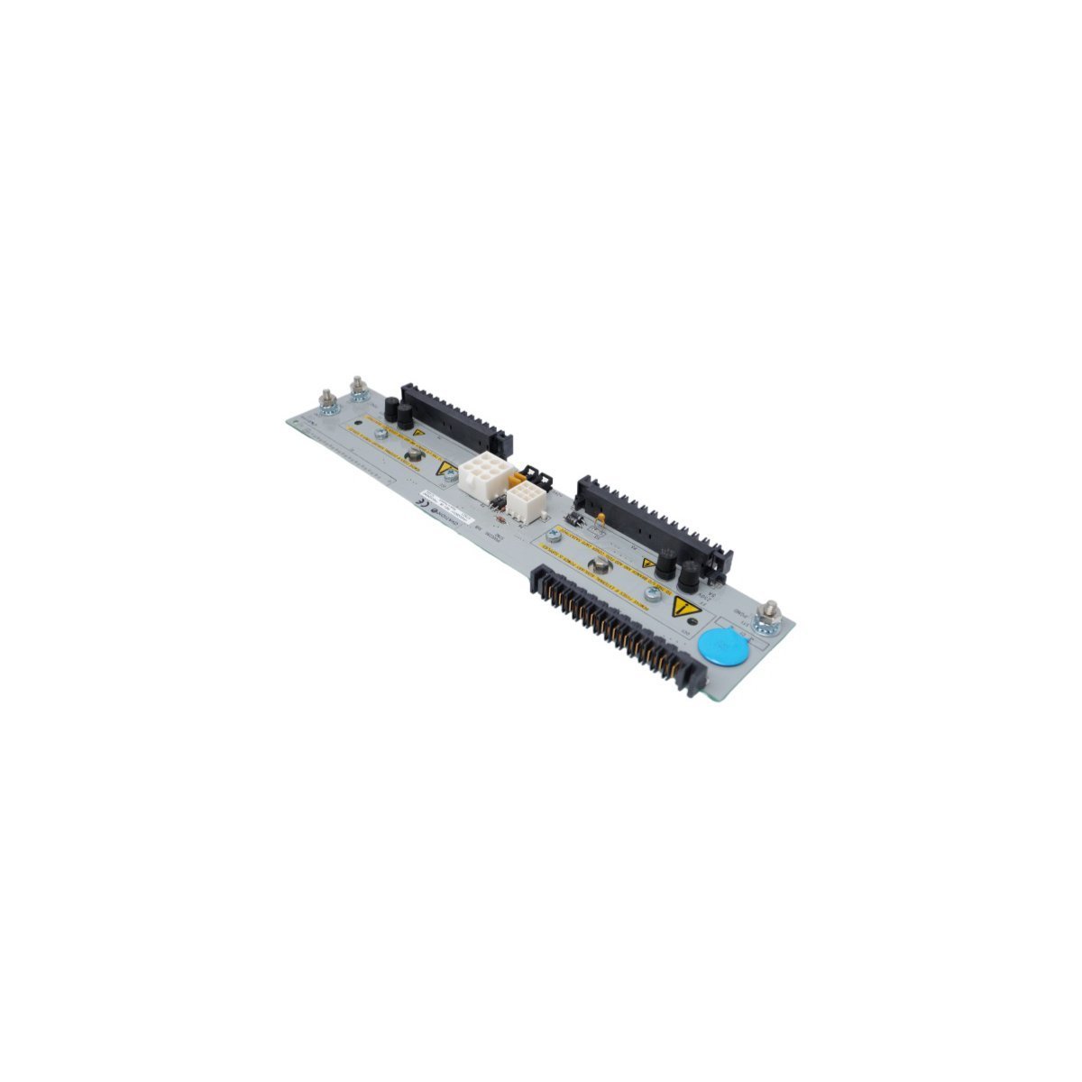
The Allen Bradley 80190-560-01-R, also cataloged as the 80190-560-01-R PC Board, operates as a dedicated hardware component for industrial communication and signal routing within PLC networks.
Hardware Specifications
| Parameter | Specification |
|---|---|
| Model | 80190-560-01-R |
| Brand | Allen Bradley |
| Origin | USA |
| Weight | 0.4 kg |
| Dimensions | 19.1 x 18.8 x 6.5 cm |
| Operating Temp | Industrial Standard |
| Power Consumption | System Backplane Dependent |
| Primary Function | Ethernet Router / Signal Processing |
Profinet and EtherNet/IP Deterministic Network Characteristics
The 80190-560-01-R leverages integrated logic to facilitate deterministic data exchange across industrial networks. Specifically, the module supports high-speed packet routing, thereby minimizing latency in Ethernet-based PLC backplane communication. Furthermore, firmware flash compatibility ensures the hardware remains synchronized with contemporary network protocols. In addition to this, I/O density scaling allows for seamless integration into complex, multi-node automation environments without compromising bus velocity. Consequently, the system maintains strict timing compliance even as network traffic demands increase.
Frequently Asked Questions
Q: Does the 80190-560-01-R support live extraction from the PLC backplane?A: No. Power must be disconnected from the chassis before installing or removing the PC Board to prevent electrical arcing or damage to backplane pin connectors.Q: How should the module be configured for network routing?A: Configuration is performed via the primary PLC programming environment, utilizing the integrated Ethernet router interface to map physical addresses to logical network tags.Field Installation Guidelines
- Ensure the control cabinet power is isolated and locked out before installation.
- Inspect the PCB edge connectors for any oxidation or mechanical deformation.
- Slide the module into the designated PLC chassis slot, ensuring the backplane connector aligns correctly with the receiving socket.
- Secure the module using the top and bottom captive screws to ensure proper grounding and mechanical stability on the DIN rail.
- Connect shielded Ethernet cabling to the designated ports, ensuring the cable shield is terminated at the cabinet common ground point to minimize EMI interference.